Posted on Leave a comment

Behringer DEQ2496 Mastering Processor

Bootscreen
Bootscreen

I was recently given this unit, along with another Behringer sound processor to repair, as the units were both displaying booting problems. This first one is a rather swish Mastering Processor, which has many features I’ll leave to Behringer to explain 😉

Input Board & Relays

All the inputs are on the back of this 19″ rackmount bit of kit, nothing much on this PCB other than the connectors & a couple of switching relays.

Main Processor PCB
Main Processor PCB

All the magic is done on the main processor PCB, which is host to 3 Analog Devices DSP processors:

ADSP-BF531 BlackFin DSP. This one is probably handling most of the audio processing, as it’s the most powerful DSP onboard at 600Mhz. There’s a ROM on board above this for the firmware & a single RAM chip. On the right are a pair of ADSP-21065  DSP processors at a lower clock rate of 66MHz. To the left is some glue logic to interface the user controls & dot-matrix LCD.

PSU Module
PSU Module

The PSU in this unit is a pretty standard looking SMPS, with some extra noise filtering & shielding. The main transformer is underneath the mu-metal shield in the centre of the board.

Posted on 12 Comments

Zhiyu ZBP30A1 Electronic Dummy Load

60W DC Electronic Load

Here’s a useful tool for testing both power supplies & batteries, a dummy load. This unit is rated up to 60W, at voltages from 1v to 25v, current from 200mA to 9.99A.
This device requires a 12v DC power source separate from the load itself, to power the logic circuitry.

Microcontroller Section

Like many of these modules, the brains of the operation is an STM8 microcontroller. There’s a header to the left with some communication pins, the T pin transmits the voltage when the unit is operating, along with the status via RS232 115200 8N1. This serial signal is only present in DC load mode, the pin is pulled low in battery test mode. The 4 pins underneath the clock crystal are the programming pins for the STM8.

Serial Comms
Serial Comms
Cooling Fan
Cooling Fan

The main heatsink is fan cooled, the speed is PWM controlled via the microcontroller depending on the temperature.

Main MOSFET
Main MOSFET

The main load MOSFET is an IRFP150N from Infineon. This device is rated at 100v 42A, with a max power dissipation of 160W. On the right is a dual diode for reverse polarity protection, this is in series with the MOSFET. On the left is the thermistor for controlling fan speed.

Load Terminals
Load Terminals

The load is usually connected via a rising clamp terminal block. I’ve replaced it with a XT60 connector in this case as all my battery holders are fitted with these. This also removes the contact resistance of more connections for an adaptor cable. The small JST XH2 connector on the left is for remote voltage sensing. This is used for 4-wire measurements.

Function 1 - DC Load
Function 1 – DC Load

Powering the device up while holding the RUN button gets you into the menu to select the operating modes. Function 1 is simple DC load.

Function 2 - Battery Capacity Mode
Function 2 – Battery Capacity Mode

The rotary encoder is used to select the option. Function 2 is battery capacity test mode.

Beeper Mode
Beeper Mode

After the mode is selected, an option appears to either turn the beeper on or off.

Amps Set
Amps Set

When in standby mode, the threshold voltage & the load current can be set. Here the Amps LED is lit, so the load current can be set. The pair of LEDs between the displays shows which digit will be changed. Pressing the encoder button cycles through the options.

Volts Set
Volts Set

With the Volts LED lit, the threshold voltage can be changed.

When in DC load mode (Fun1), the device will place a fixed load onto the power source until it’s manually stopped. The voltage setting in this mode is a low-voltage alarm. The current can be changed while the load is running.

When in battery discharge test mode (Fun2), the voltage set is the cutoff voltage – discharge will stop when this is reached. Like the DC load mode, the current can be changed when the load is running. After the battery has completed discharging, the capacity in Ah & Wh will be displayed on the top 7-segment. These results can be selected between with the encoder.

Below are tables with all the options for the unit, along with the error codes I’ve been able to decipher from the Chinese info available in various places online. (If anyone knows better, do let me know!).

OptionFunction
Fun1Basic DC Load
Fun 2Battery Capacity Test
BeOnBeeper On
BeOfBeeper Off
Error CodeMeaning
Err1Input Overvoltage
Err2Low Battery Voltage / No Battery Present / Reverse Polarity
Err3Battery ESR Too High / Cannot sustain selected discharge current
Err4General Failure
Err6Power Supply Voltage Too Low / Too High. Minimum 12v 0.5A.
otPOvertemperature Protection
ErtTemperature Sensor Failure / Temperature Too Low
ouPPower Supply Overvoltage Protection
oPPLoad Power Protection
Posted on Leave a comment

OLED Pulse Oximeter Teardown

OLED Pulse Oximeter
OLED Pulse Oximeter

Here’s a piece of medical equipment that in recent years has become extremely cheap, – a Pulse Oximeter, used to determine the oxygen saturation in the blood. These can be had on eBay for less than £15.

Powered On
Powered On

This one has a dual colour OLED display, a single button for powering on & adjusting a few settings. These cheap Oximeters do have a bit of a cheap plastic feel to them, but they do seem to work pretty well.

Pulse Oximeter
Pulse Oximeter

After a few seconds of being applied to a finger, the unit gives readings that apparently confirm that I’m alive at least. 😉 The device takes a few seconds to get a baseline reading & calibrate the sensor levels.

Main PCB Top
Main PCB Top

The plastic casing is held together with a few very small screws, but comes apart easily. here is the top of the main board with the OLED display panel. There appears to be a programming header & a serial port on the board as well. I’ll have to poke at these pads with a scope to see if any useful data is on the pins.

Main PCB Bottom
Main PCB Bottom

The bottom of the board has all the main components of the system. The microcontroller is a STM32F03C8T6, these are very common in Chinese gear these days. There’s a small piezo beeper & the main photodiode detector is in the centre.
There is an unpopulated IC space on the board with room for support components. I suspect this would be for a Bluetooth radio, as there’s a space at the bottom left of the PCB with no copper planes – this looks like an antenna mounting point. (The serial port on the pads is probably routed here, for remote monitoring).
At the top left are a pair of SGM3005 Dual SPDT analogue switches. These will be used to alternate the red & IR LEDs on the other side of the shell.
A 4-core FFC goes off to the other side of the shell, bringing power from the battery & supplying the sensing LEDs.

Battery Compartment
Battery Compartment

Power is supplied by a pair of AAA cells in the other shell.

Dual LED
Dual LED

The sensor LEDs are tucked in between the cells, this dual-diode package has a 660nm red LED & a 940nm IR LED.

Posted on Leave a comment

eBay Chinese Chassis Power Supply S-400-12 400W 12v 33A

S-400-12 PSU
S-400-12 PSU

Here’s a cheap PSU from the treasure trove of junk that is eBay, rated at a rather beefy 400W of output at 12v – 33A! These industrial-type PSUs from name brands like TDK-Lambda or Puls are usually rather expensive, so I was interested to find out how much of a punishment these cheap Chinese versions will take before grenading. In my case this PSU is to be pushed into float charging a large lead acid battery bank, which when in a discharged state will try to pull as many amps from the charger as can be provided.

Rating Label
Rating Label

These PSUs are universal input, voltage adjustable by a switch on the other side of the PSU, below. The output voltage is also trimmable from the factory, an important thing for battery charging, as the output voltage needs to be sustained at 13.8v rather than the flat 12v from the factory.

Input Voltage Selector
Main Terminal Block
Main Terminal Block

Mains connections & the low voltage outputs are on beefy screw terminals. The output voltage adjustment potentiometer & output indicator LED are on the left side.

Cooling Fan
Cooling Fan

The cooling fan for the unit, which pulls air through the casing instead of blowing into the casing is a cheap sleeve bearing 60mm fan. No surprises here. I’ll probably replace this with a high-quality ball-bearing fan, to save the PSU from inevitable fan failure & overheating.

PCB Bottom
PCB Bottom

The PCB tracks are generously laid out on the high current output side, but there are some primary/secondary clearance issues in a couple of places. Lindsay Wilson over at Imajeenyus.com did a pretty thorough work-up on the fineries of these PSUs, so I’ll leave most of the in-depth stuff via a linky. There’s also a modification of this PSU for a wider voltage range, which I haven’t done in this case as the existing adjustment is plenty wide enough for battery charging duty.

Bare PCB
Bare PCB

The PCB is laid out in the usual fashion for these PSUs, with the power path taking a U-route across the board. Mains input is lower left, with some filtering. Main diode bridge in the centre, with the voltage selection switch & then the main filter caps. Power is then switched into the transformer by the pair of large transistors on the right before being rectified & smoothed on the top left.

Main Switching Transistors

The pair of main switching devices are mounted to the casing with thermal compound & an insulating pad. To bridge the gap there’s a chunk of aluminium which also provides some extra heatsinking.

SMPS Drive IC & Base Drive Transformer

The PSU is controlled by a jelly-bean TL494 PWM controller IC. No active PFC in this cheap supply so the power factor is going to be very poor indeed.

Input Protection
Input Protection

Input protection & filtering is rather simple with the usual fuse, MOV filter capacitor & common mode choke.

Main Output Rectifiers

Beefy 30A dual diodes on the DC output side, mounted in the same fashion as the main switching transistors.

Output Current Shunt

Current measurement is done by these large wire links in the current path, selectable for different models with different output ratings.

Hot Glue Support
Hot Glue Support

The output capacitors were just floating around in the breeze, with one of them already having broken the solder joints in shipping! After reflowing the pads on all the capacitors some hot glue as flowed around them to stop any further movement.

This supply has now been in service for a couple of weeks at a constant 50% load, with the occasional hammering to recharge the battery bank after a power failure. at 13A the supply barely even gets warm, while at a load high enough to make 40A rated cable get uncomfortably warm (I didn’t manage to get a current reading, as my instruments don’t currently go high enough), the PSU was hot in the power semiconductor areas, but seemed to cope at full load perfectly well.

Posted on Leave a comment

Inductive Hour Counter / Tachometer – Petrol Engines

As one of my current projects involves a small petrol engine – a Honda GX35 clone, I figured an hour counter would be very handy to keep an eye on service intervals. (More to come on the engine itself later on). I found a device that would suit my needs on good old eBay.

Inductive Engine Monitor

These engine monitors are pretty cheap, at about £4. The sensing is done by a single heat-resistant silicone wire, that wraps around the HT lead to the spark plug. The unit can be set for different firing intervals via the buttons. In the case of most single-cylinder 4-stroke engines, the spark plug fires on every revolution – wasted-spark ignition. This simplifies the ignition system greatly, by not requiring the timing signal be driven from 1/2 crankshaft speed. The second “wasted” spark fires into the exhaust stroke, so has no effect.

Internals
Internals

The back cover is lightly glued into place with a drop of cyanoacrylate in opposite corners, but easily pops off. The power is supplied by a soldered-in 3v Lithium cell. The main microcontroller has no number laser etched on to it at all – it appears it skipped the marking machine.

Input Filtering
Input Filtering

The input from the sensing wire comes in through a coupling capacitor & is amplified by a transistor. It’s then fed into a 74HC00D Quad 2-Input NAND gate, before being fed into the microcontroller.

Pickup
Pickup

The pickup wire is simply wound around the spark plug lead. I’ve held it in position here with some heatshrink tubing. Heat in this area shouldn’t be an issue as it’s directly in the airflow from the flywheel fan.

Posted on 6 Comments

Sony Watchman FD-20 Flat CRT TV Teardown

Sony Watchman FD-20
Sony Watchman FD-20

Here’s an oddity from the 1980’s – a CRT-based portable TV, with a very strangely shaped tube. Sony produced many types of flat CRTs back in the 80’s, with the electron gun at 90° to the curved phosphor screen.

Front Panel
Front Panel

The front panel has the display window, along with the tuning & volume indicators. Unfortunately since analogue TV transmissions have long been switched off, this unit no longer picks up any transmissions off the air, but it can be modified to accept a composite video input.

Back Panel
Back Panel

The back panel has the battery compartment & the tilt stand.

Certification
Certification

The certification label reveals this unit was manufactured in May 1984, 32 years ago!

Spec. Label
Spec. Label

Rated at 6v, ~2.1W this device uses surprisingly little power for something CRT based.

Battery Holder
Battery Holder

The battery holder is a little unique, this plastic frame holds 4 AA cells, for a 6v pack.

Battery Compartment
Battery Compartment

The battery holder slots into the back of the TV, there’s also an extra contact that the service manual mentions is for charging, so I assume a rechargeable 6v battery pack was also available.

Front Panel Removed
Front Panel Removed

Removing a pair of pin-spanner type screws allows the front glass & screen printed CRT surround to be removed. Not much more under here other than the pair of screws that retain the CRT in the front frame.

Back Cover Removed
Back Cover Removed

Here’s the back cover removed, after unscrewing some very small screws. As per usual with Sony gear, the electronics is extremely compacted, using many flat flex cables between the various PCBs. The main PCB is visible at the back, this has all the deflection circuitry, RF tuner, Video IF, Audio IF, video amplifier & composite circuitry.

CRT Electron Gun & Flyback Transformer

Lifting up the main board reveals more PCBs – the high voltage section for the CRT with the flyback transformer, focus & brightness controls is on the left. The loudspeaker PCB is below this. The CRT electron gun is tucked in behind the flyback transformer, it’s socket being connected to the rest of the circuitry with a flat flex cable.

CRT Rear
CRT Rear

Here’s the back of the CRT, the phosphor screen is on the other side of the curved glass back. These tubes must require some additional deflection complexity, as the geometry will change as the beam scans across the screen. There’s a dynamic focus circuit on the schematics, along with extensive keystone adjustments.

Sony 02-JM Flat CRT
Sony 02-JM Flat CRT

Here’s the tube entirely extracted from the chassis. The EHT connection to the final anode is on the side of the tube bell, the curved phosphor screen is clearly visible. The one thing I can’t find in this CRT is a getter spot, so Sony may have a way of getting a pure enough vacuum that one isn’t required.

I’d expect the vertical deflection waveforms to be vastly different on this kind of CRT, due to the strange screen setup. Not much of a beam movement is required to move the spot from the top to the bottom of the screen.

HV Module
HV Module

No doubt to keep the isolation gaps large, all the high voltages are kept on a separate small PCB with the flyback transformer. This board generates the voltages for the electron gun filament, focus grid & the bias to set the beam current (brightness) as well.

Bare CRT
Bare CRT

Here the deflection yoke has been removed from the CRT, showing the very odd shape better. These tubes are constructed of 3 pieces of glass, the bell with electron gun, back glass with phosphor screen & front viewing window glass. All these components are joined with glass frit.

Electron Gun
Electron Gun

The electron gun in the neck looks to be pretty much standard, with all the usual electrodes.

Viewing Window
Viewing Window

Here’s a view from the very top of the CRT, the curve in the screen is very obvious here. The electron beam emerges from the bell at the back.

FD-20 Schematic
FD-20 Schematic

Here’s the full schematic of the entire TV, I extracted this from a service manual I managed to find online.

More to come on hacking this unit to accept a standard composite video input, from something such as a Raspberry Pi!

Posted on Leave a comment

Aspen Universal Condensate Pump

Universal Peristaltic Condensate Pump

Here’s another piece of commercial gear, from an industrial air conditioning unit. These pumps are used to drain the condensate from the evaporator unit, so water doesn’t end up raining down from the ceiling.

Pump Head
Pump Head

This is a peristaltic pump, with a silicone hose forming the pumping element.

Rear Panel
Rear Panel

The test switch & electrical connections are on the back, along with the data label.

Power & Sensor Socket

The electrical connections are all on a single 5-pin socket. Along with 240v AC mains, there are a pair of thermistors connected to the unit, which switch the pump on when a 5°C temperature difference across the evaporator coil is detected. When air is cooled, it’s capacity for moisture drops, so the water condenses out on the coil.

Roller Wheel
Roller Wheel

Here the front cover has been removed from the pump, showing the silicone tube & roller wheel. The wheel was originally Cadmium-plated, but exposure to the elements has oxidized this into highly toxic Cadmium Oxide.

Pump Rollers
Pump Rollers

Here you can see the rollers. These pinch the tube at the inlet, and the rotation carries a slug of liquid through the tube to the outlet side.

Pump Tube
Pump Tube

Here’s the tube itself, the main wearing part of the pump. This is replaceable as a spare part.

Motor & Gearbox
Motor & Gearbox

Inside the casing is a shaded-pole motor, connected to a large gearbox, to give the slow rotation for the pump head. The rated speed is 51RPM.

Control PCB
Control PCB

There’s not much to the control PCB. The large resistor forms a voltage dropper, to reduce the mains 240v to a more suitable level for the logic. There’s a TL062C Low-Power JFET Op-Amp & a CD4060BCM 14-stage binary ripple counter forming the logic. The set point is adjustable via the potentiometer.

Pump Triac
Pump Triac

The pump motor is switched via this Z7M SMD triac, not much switching power is needed here as the motor is only a very small shaded-pole type.

Posted on Leave a comment

Motorola Cordless DECT Phone Teardown

Motorola DECT Phone
Motorola DECT Phone

Another random teardown from the junk box time!
Here’s an old Motorola DECT landline phone, no use to me as I’ve not used a landline for many years.

Battery Compartment
Battery Compartment

Not much on the back, other than the battery compartment for a pair of AAA rechargables. The base unit contains the charger.

Main PCB
Main PCB

Here’s the main PCB removed from it’s casing. There’s not really much going on, one of the main ICs, which is probably a microcontroller, is a COB device, so no part numbers from there. There’s a row of pads for programming the device at the factory. The RF section is on a dedicated IC, a DE19RF19ZCNC from DSP Group. I couldn’t find much on this part, but it’s one of a range of DECT/VoIP DSP devices.


Base Unit PCB
Base Unit PCB

Inside the base unit is a similar board, just without the keypad. Main microcontroller is again a COB device, the RF IC is under the shield.

Main Chipset
Main Chipset

Removing the shield reveals the same IC as in the handset, only this PCB has a pair of antennas.

He-Ne Laser Safety

As with *any* laser, proper precautions must be taken to avoid any possibility of damage to vision. The types of He-Ne lasers mostly dealt with in this document are rated Class II, IIIa, or the low end of IIIb (see the section: Laser Safety Classifications. For most of these, common sense (don’t stare into the beam) and fairly basic precautions suffice since the reflected or scattered light will not cause instantaneous injury and is not a fire hazard.

However, unlike those for laser diodes, He-Ne power supplies utilize high voltage (several kV) and some designs may be potentially lethal. This is particularly true of AC line powered units since the power transformer may be capable of much more current than is actually required by the He-Ne laser tube – especially if it is home built using the transformer from some other piece of equipment (like an old tube type console TV or that utility pole transformer you found along the curb) which may have a much higher current rating.

The high quality capacitors in a typical power supply will hold enough charge to wake you up – for quite a while even after the supply has been switched off and unplugged. Depending on design, there may be up to 10 to 15 kV or more (but on very small capacitors) if the power supply was operated without a He-Ne tube attached or it did not start for some reason. There will likely be a lower voltage – perhaps 1 to 3 kV – on somewhat larger capacitors. Unless significantly oversized, the amount of stored energy isn’t likely to be enough to be lethal but it can still be quite a jolt. The He-Ne tube itself also acts as a small HV capacitor so even touching it should it become disconnected from the power supply may give you a tingle. This probably won’t really hurt you physically but your ego may be bruised if you then drop the tube and it then shatters on the floor!

However, should you be dealing with a much larger He-Ne laser, its power supply is going to be correspondingly more dangerous as well. For example, a 35 mW He-Ne tube typically requires about 8 mA at 5 to 6 kV. That current may not sound like much but the power supply is likely capable of providing much more if you are the destination instead of the laser head (especially if it is a home-made unit using grossly oversized parts)! It doesn’t take much more under the wrong conditions to kill.

After powering off, use a well insulated 1M resistor made from a string of ten 100K, 2 W metal film resistors in a glass or plastic tube to drain the charge – and confirm with a voltmeter before touching anything. (Don’t use carbon resistors as I have seen them behave funny around high voltages. And, don’t use the old screwdriver trick – shorting the output of the power supply directly to ground – as this may damage it internally.)

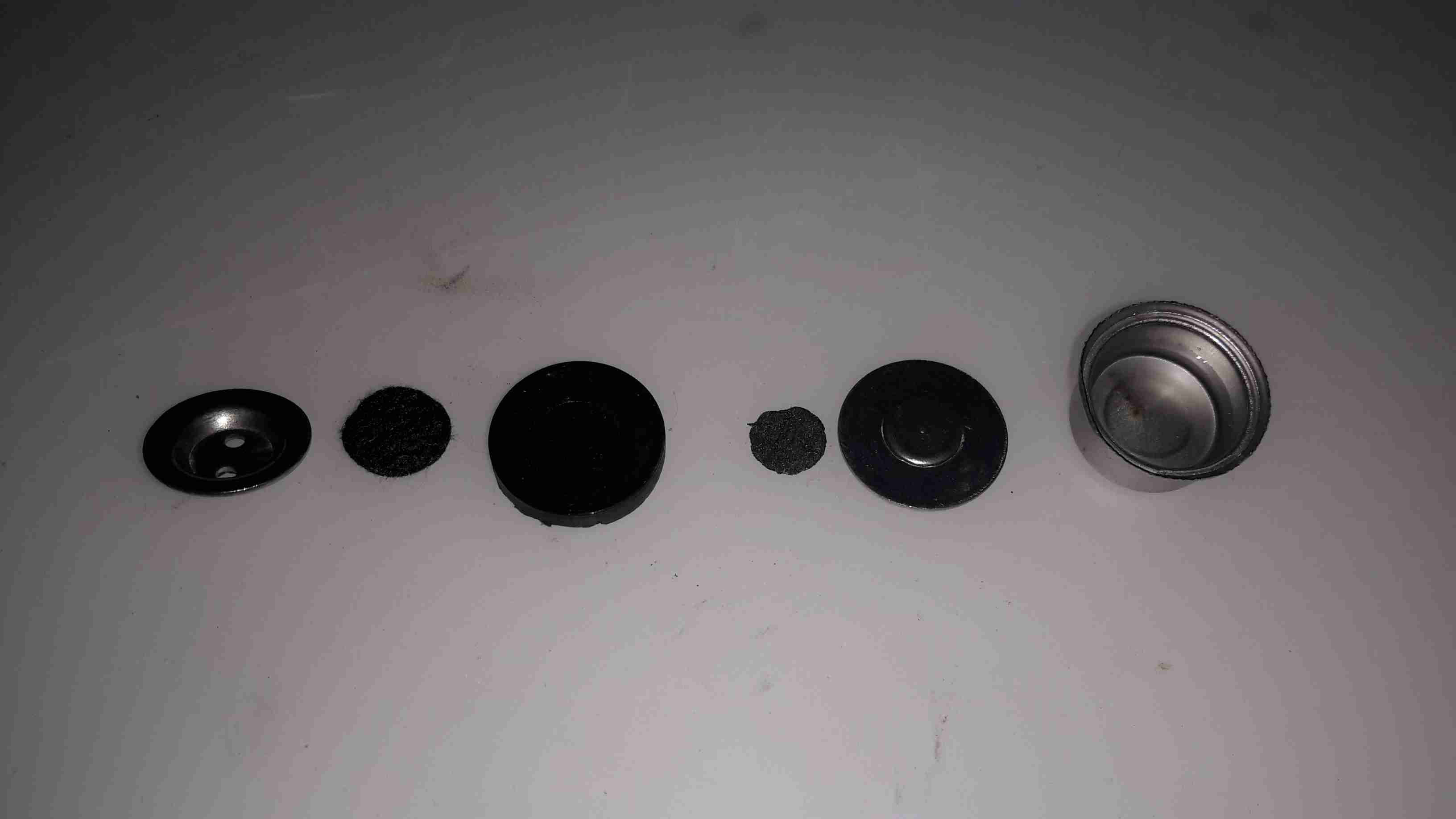
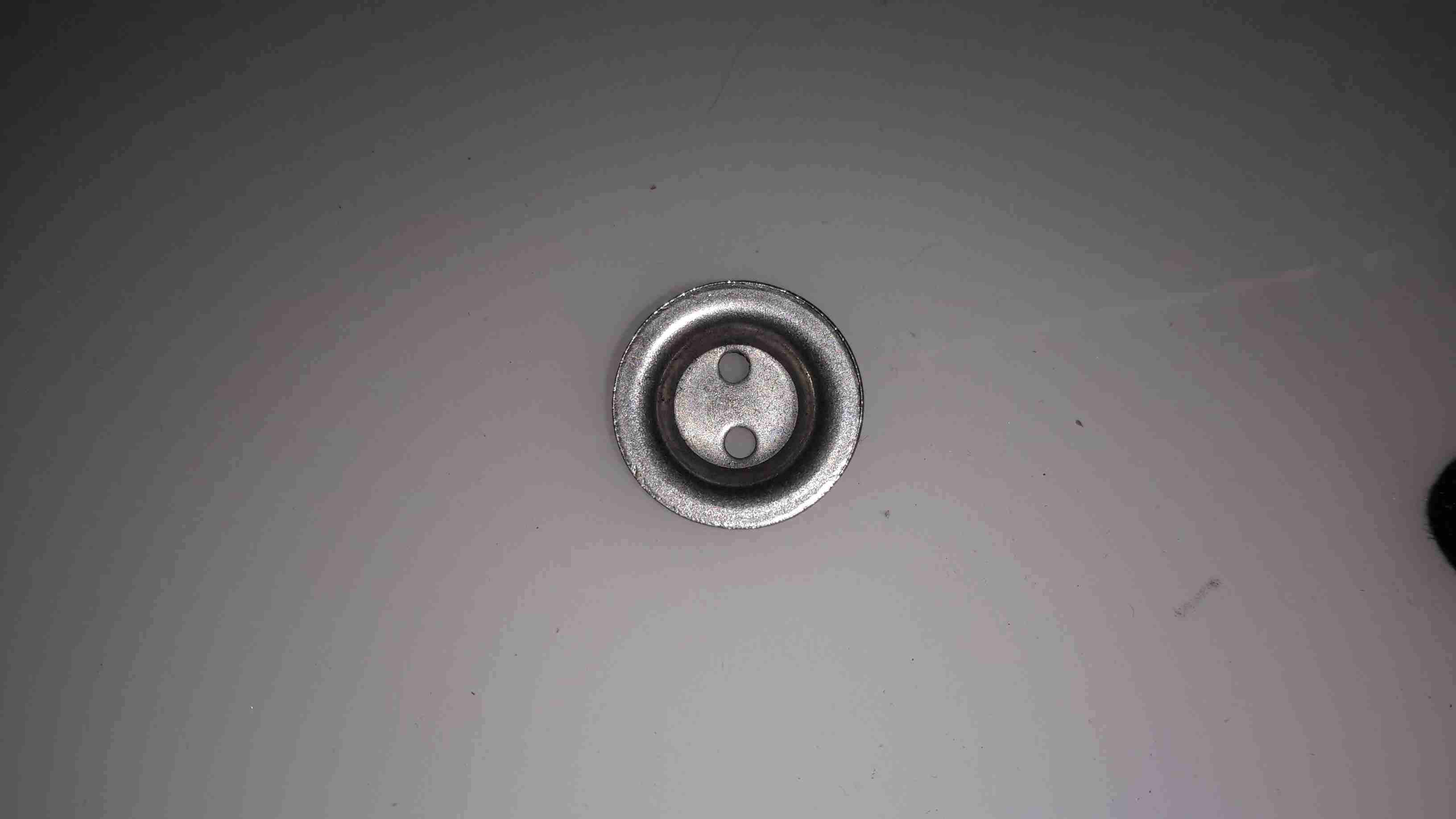
And only change electrical connections or plug/unplug connectors with power OFF, being aware of the potential for stored charge. In particular, the aluminium cylinder of some HeNe laser heads is the negative return for the tube current via a spring contact inside the rear end-cap. So, pulling off the rear end-cap while the laser is powered will likely make YOU the negative return instead! You will probably then bounce off the ceiling while the laser bounces off the floor, which can easily ruin your entire day in more ways than one. 🙁 🙂 This connection scheme is known to be true for most JDS Uniphase and many Melles Griot laser heads, but may apply to others as well.

Now, for some first-hand experience:

(From: Doug (dulmage@skypoint.com).)

Well, here’s where I embarrass myself, but hopefully save a life…

I’ve worked on medium and large frame lasers since about 1980 (Spectra-Physics 168’s, 171’s, Innova 90’s, 100’s and 200’s – high voltage, high current, no line isolation, multi-kV igniters, etc.). Never in all that time did I ever get hurt other than getting a few retinal burns (that’s bad enough, but at least I never fell across a tube or igniter at startup). Anyway, the one laser that almost did kill me was also the smallest that I ever worked on.

I was doing some testing of AO devices along with some small cylindrical HeNe tubes from Siemens. These little coax tubes had clips for attaching the anode and cathode connections. Well, I was going through a few boxes of these things a day doing various tests. Just slap them on the bench, fire them up, discharge the supplies and then disconnect and try another one. They ran off a 9 VDC power supply.

At the end of one long day, I called it quits early and just shut the laser supply off and left the tube in place as I was just going to put on a new tube in the morning. That next morning, I came and incorrectly assumed that the power supply would have discharged on it own overnight. So, with each hand I stupidly grab one clip each on the laser to disconnect it. YeeHaaaaaaaaa!!!!. I felt like I had been hid across my temples with a two by four. It felt like I swallowed my tongue and then I kind of blacked out. One of the guys came and helped me up, but I was weak in the knees, and very disoriented.

I stumbled around for about 15 minutes and then out of nowhere it was just like I got another shock! This cycle of stuff went on for about 3 hours, then stopped once I got to the hospital. I can’t even remember what they did to me there. Anyway, how embarrassing to almost get killed by a HeNe laser after all that other high power stuff that I did. I think that’s called ‘irony’.

Comments on HeNe Laser Safety Issues

(Portions from: Robert Savas (jondrew@mail.ao.net).)

A 10 mw HeNe laser certainly presents an eye hazard.

According to American National Standard, ANSI Z136.1-1993, table 4 Simplified Method for Selecting Laser Eye Protection for Intrabeam Viewing, protective eyewear with an attenuation factor of 10 (Optical Density 1) is required for a HeNe with a 10 milliwatt output. This assumes an exposure duration of 0.25 to 10 seconds, the time in which they eye would blink or change viewing direction due the uncomfortable illumination level of the laser. Eyeware with an attenuation factor of 10 is roughly comparable to a good pair of sunglasses (this is NOT intended as a rigorous safety analysis, and I take no responsibility for anyone foolish enough to stare at a laser beam under any circumstances). This calculation also assumes the entire 10 milliwatts are contained in a beam small enough to enter a 7 millimeter aperture (the pupil of the eye). Beyond a few meters the beam has spread out enough so that only a small fraction of the total optical power could possible enter the eye.

Posted on Leave a comment

Sky+ HD Set Top Box

Sky Box
Sky Box

Time for another teardown! I managed to fish this Sky+ box out of a skip, but to protect the guilty, all serial numbers have been removed.
These are pretty smart devices, with DVR capability on board.

Ports 1
Ports 1

There’s a lot of ports on these units, from RS-232 serial, POTS modem, eSATA, HDMI, USB, Ethernet, SCART, Optical, digital outputs & even composite video.

Ports 2
Ports 2
Ports 3
Ports 3
Top Panel
Top Panel

Removing the top plastic cover reveals the operation buttons & the built in WiFi adaptor, which is USB connected to the main logic board.

Front Panel
Front Panel

The PCB on the front of the chassis has all the indicators, and the IR Receiver for the remote.

Cover Removed
Cover Removed

Removing the top shield of the chassis reveals the innards. The PSU is on the top right, 500GB SATA disk drive in the bottom centre. The main logic PCB is top centre.

Logic PCB
Logic PCB

Here’s the main logic PCB. The massive heatsink in the middle is cooling the main SoC, below.

SoC
SoC

The main SoC in this unit is a Broadcom BCM7335 HD PVR Satellite System-On-Chip. It’s surrounded by it’s boot flash, a Spansion GL512P10FFCR1 512Mbit NOR device. It’s also got some DRAM around the left edge.

Smart Card Reader
Smart Card Reader

The smart card reader is on the PSU PCB, the controller here is an NXP TDA8024

PSU PCB
PSU PCB

The PSU itself is a pretty standard SMPS, so I won’t go too far into that particular bit. The logic PCB attaches to the large pin header on the left of the PSU, some of the analogue video outputs are also on this board.
There’s also a Microchip PIC16F726 microcontroller on this PCB, next to the pin header. Judging by the PCB traces, this handles everything on the user control panel.

Power Supplies
Power Supplies

Some local supplies are provided on the logic board for the main SoC, the IC in the centre here is an Allegro A92 DC-DC converter. I didn’t manage to find a datasheet for this one.

LNB Front End
LNB Front End

The RF front end for the satellite input is a Broadcom BCM3445 Low Noise Amplifier & Splitter, again not much info on this one.

RS232 Section
RS232 Section

The standard MAX232 is used for the serial interface. I imagine this is for diagnostics.

Modem
Modem

The POTS modem section is handled by a Si2457 System-Side device & Si3018 Line-Side device pair.

Posted on 2 Comments

Eberspacher D5W ECU Constant Overheat Error

Eberspacher ECU 25 1599 50 00 00

Here’s another Eberspacher control unit, this time from an ancient D5W 5kW water heater. The system in this case is just flaky – sometimes the heater will start without fault & run perfectly, then suddenly will stop working entirely.
The error codes are read on these very old units via an indicator lamp connected to a test terminal. In this case the code was the one for Overheat Shutdown.

Considering this fault occurs when the heater is stone cold, I figured it was either a fault with the sensor itself or the ECU.

Temperature Sensor
Temperature Sensor

The temperature sensor is located on the heat exchanger, right next to the hot water outlet fitting. I’m not sure what the spec is, but it reads exactly 1KΩ at room temperature.

ECU PCB
ECU PCB

The PCB is held into the aluminium can by means of crimps around the edge that lock into the plastic terminal cover. Inserting a screwdriver & expanding the crimps allows the PCB to be slid out.

Casing Crimps
Casing Crimps

The factory date stamp on the microcontroller dates this unit to March 1989 – considerably older than I expected!
Unlike the newer versions that use transistors, this ECU has a bunch of PCB relays to do the high current switching of the water pump motor, fan motor & glowplug.
Overall the board looks to be solidly constructed, with silicone around all the larger components.

ECU PCB Solder Side
ECU PCB Solder Side

Here’s the solder side of the PCB, which has a generous coating of sealant to keep moisture out.

Bad Joint Closeup
Bad Joint Closeup

Looking at the solder joints for the row of relays on the top side of the PCB, it looks like that there’s some dry joints here.
I suspect that years of vibration has taken it’s toll, as the relays are otherwise unsupported. It wouldn’t be possible to use silicone to secure these devices as they are completely open – any sealant would likely stop them from operating.

Resoldered Joints
Resoldered Joints

Using a very hot soldering iron I managed to get the joints to reflow properly, using lots of flux to make sure the conformal coating didn’t interfere with the reflow.

Posted on Leave a comment

Digital Angle Gauge

Front
Front

Here’s a useful tool for the kit, a digital angle gauge/protractor. These use a silicon sensor to show the number of degrees the unit is out of level.

Magnets!
Magnets!

Magnets are provided in the base, so the tool can attach to any ferrous surface.

Battery Box
Battery Box

Power is provided by a single AAA cell.

Main PCB
Main PCB

Removing the rear cover reveals the brains of the unit, and there’s not much to it at all. The main microcontroller is a CoB-type device, so no part numbers available from that one.

Sensing Element
Sensing Element

The IC to the left of the main microcontroller is the sensing element. There’s no markings on this inclinometer IC so I’m not sure of the specs, but it will be a 3D-MEMS device of some sort.

Power Supply
Power Supply

The other side of the PCB has the power supply for the logic, and a serial EEPROM, probably storing calibration data.

Posted on Leave a comment

Mini USB Soldering Iron

USB Soldering Iron
USB Soldering Iron

Here’s a novel little gadget, a USB powered soldering iron. The heating tip on these is very small & might be useful for very small SMD work. Bigger joints not so much, as it’s only rated at 8W. (Still breaks the USB standard of 2.5W from a single port).

These irons aren’t actually too bad to use, as long as the limitations in power are respected. Since nearly everything has a USB power port these days, it could make for a handy emergency soldering iron.

Heater Socket
Heater Socket

The heater & soldering bit are a single unit, not designed to be replaced separately. (I’ve not managed to find replacement elements, but at £3 for the entire iron, it would be pretty pointless).
Above is the socket where the heater plugs in, safely isolating the plastic body from any stray heat.

DC Input Jack
DC Input Jack

The DC input is a 3.5mm audio jack, a non-standard USB to 3.5mm jack cable is supplied. Such non-standard cables have the potential to damage equipment that isn’t expecting to see 5v on an audio input if it’s used incorrectly.

Touch Sensor & LED
Touch Sensor & LED

There isn’t actually a switch on this unit for power management, but a clever arrangement of a touch button & vibration switch. The vertical spring in the photo above makes contact with a steel ball bearing pressed into the plastic housing, forming the touch contact.

MOSFET
MOSFET

The large MOSFET here is switching the main heater current, the silver cylinder in front is the vibration switch, connected in parallel with the touch button.

PCB
PCB

The main controller is very simple. It’s a 555 timer configured in monostable mode. Below is a schematic showing the basic circuit.

555 Monostable
555 Monostable

Big Clive also did a teardown & review of this iron. Head over to YouTube to watch.

Posted on 14 Comments

Dyson DC16 Handheld Teardown

DC16
DC16

The Dyson DC16 is one of the older handheld vacuums, before the introduction of the “Digital Motor”. (Marketing obviously didn’t think “Switched Reluctance Motor” sounded quite as good).

These vacuums have a very large DC brush motor driving the suction turbine instead, the same as would be found in a cordless power tool.

Control PCB
Control PCB

Popping the front cap off with the ID label, reveals the brains of the vacuum. The two large terminals at the right are for charging, which is only done at 550mA (0.5C). There are two PIC microcontrollers in here, along with a large choke, DC-DC converter for supplying the logic most likely. The larger of the MCUs, a PIC16HV785, is probably doing the soft-start PWM on the main motor, the smaller of the two, a PIC16F684 I’m sure is doing battery charging & power management. The motor has a PCB on it’s tail end, with a very large MOSFET, a pair of heavy leads connect directly from the battery connector to the motor.
Just out of sight on the bottom left edge of the board is a Hall Effect Sensor, this detects the presence of the filter by means of a small magnet, the vacuum will not start without a filter fitted.

Battery Pack
Battery Pack

The battery pack is a large custom job, obviously. 4 terminals mean there’s slightly more in here than just the cells.

Battery Cracked
Battery Cracked

Luckily, instead of ultrasonic or solvent welding the case, these Dyson batteries are just snapped together. Some mild attack with a pair of screwdrivers allows the end cap to be removed with minimal damage.

Cells
Cells

The cells were lightly hot-glued into the shell, but that can easily be solved with a drop of Isopropanol to dissolve the glue bond. The pack itself is made up of 6 Sony US18650VT High-Drain 18650 Li-Ion cells in series for 21.6v nominal. These are rated at a max of 20A discharge current, 10A charge current, and 1.3Ah capacity nominal.
There’s no intelligence in this battery pack, the extra pair of terminals are for a thermistor, so the PIC in the main body knows what temperature the pack is at – it certainly gets warm while in use due to the high current draw.

Motor
Motor

Hidden in the back side of the main body is the motor. Unfortunately I wasn’t able to get this out without doing some damage, as the wiring isn’t long enough to free the unit without some surgery.

Turbine
Turbine

The suction is generated by a smaller version of the centrifugal high-speed blowers used in full size vacuums. Not much to see here.

Unofficial Charger
Unofficial Charger

Since I got this without a charger, I had to improvise. The factory power supply is just a 28v power brick, all the charging logic is in the vacuum itself, so I didn’t have to worry about such nasties as over-charging. I have since fitted the battery pack with a standard Li-Po balance cable, so it can be used with my ProCell charger, which will charge the pack in 35 minutes, instead of the 3 hours of the original charger.

Posted on Leave a comment

Multifunction LCD Power Meter MHF-8020P

LCD Unit
LCD Unit

I recently came across these on eBay, so I thought I’d grab one to see how they function, with all the metrics they display, there’s potential here for them to be very useful indeed.
One of the best parts is that no wiring is required between the sensor board & the LCD head unit – everything is transmitted over a 2.4GHz data link using NRF24L01 modules.
Above is the display unit, with it’s colour LCD display. Many features are available on this, & they appear to be designed for battery powered systems.

Monitor PCB
Monitor PCB

Another PCB handles the current & voltage sensing, so this one can be mounted as close to the high current wiring as possible.

Monitor PCB Microcontroller

The transmitter PCB is controlled with an STM8S003F3 microcontroller from ST Microelectronics. This is a Flash based STM with 8KB of ROM, 1KB of RAM & 10-bit ADC. The NRF24L01 transceiver module is just to the left.
There’s only a single button on this board, for pairing both ends of the link.

Output MOSFET
Output MOSFET

The high current end of the board has the 0.0025Ω current shunt & the output switch MOSFET, a STP75NF75 75v 75A FET, also from ST Microelectronics. A separate power source can be provided for the logic via the blue terminal block instead of powering from the source being measured.

LCD Unit Rear
LCD Unit Rear

Here’s the display unit, only a pair of power terminals are provided, 5-24v wide-range input is catered for.

LCD Unit PCB
LCD Unit PCB

Unclipping the back of the board reveals the PCB, with another 2.4GHz NRF24L01 module, and a STM8S005K6 microcontroller in this case. The switching power supply that handles the wide input voltage is along the top edge of the board.

Unfortunately I didn’t get any instruction manual with this, so some guesswork & translation of the finest Chinglish was required to get my head round the way everything works. To make life a little easier for others that might have this issue, here’s a list of functions & how to make them work.

LCD Closeup
LCD Closeup

On the right edge of the board is the function list, a quick press of the OK button turns a function ON/OFF, while holding it allows the threshold to be set.
When the output is disabled by one of the protection functions, turning that function OFF will immediately enable the output again.
The UP/DOWN buttons obviously function to select the desired function with the cursor just to the left of the labels. Less obviously though, pressing the UP button while the very top function is selected will change the Amp-Hours display to a battery capacity icon, while pressing DOWN while the very bottom function is selected will change the Watts display to Hours.
The round circle to the right displays the status of a function. Green for OK/ON Grey for FAULT/OFF.

  • OVP: Over voltage protection. This will turn off the load when the measured voltage exceeds the set threshold.
  • OPP: Over power protection. This function prevents a load from pulling more than a specified number of watts from the supply.
  • OCP: Over current protection. This one’s a little more obvious, it’ll disable the output when the current measured exceeds the specified limit.
  • OUT: This one is the status of the output MOSFET. Can also be used to manually enable/disable the output.
  • OFT: Over time protection. This one could be useful when charging batteries, if the output is enabled for longer than the specified time, the output will toggle off.
  • OAH: Over Amp-Hours protection. If the counted Amp-Hours exceeds the set limit, the output will be disabled.
  • Nom: This one indicates the status of the RF data link between the modules, and can be used to set the channel they operate on.
    Pairing is achieved by holding the OK button, selecting the channel on the LCD unit, and then pressing the button on the transmitter board. After a few seconds, (it appears to scan through all addresses until it gets a response) the display will resume updating.
    This function would be required if there are more than a single meter within RF range of each other.

I’ve not yet had a proper play with all the protection functions, but a quick mess with the OVP setting proved it was very over-sensitive. Setting the protection voltage to 15v triggered the protection with the measured voltage between 12.5v-13.8v. More experimentation is required here I think, but as I plan to just use these for power monitoring, I’ll most likely leave all the advanced functions disabled.

Posted on Leave a comment

Chinese CO Meter – The Sensor Cell

As the CO meter I bought on eBay didn’t register anything whatsoever, I decided I’d hack the sensor itself apart to make sure it wasn’t just an empty steel can. It turns out that it’s not just an empty can, but there are some reasons why the thing doesn’t work 😉

Cell Disassembled
Cell Disassembled

The cell was crimped together under the yellow shrinkwrap, but that’s nothing my aviation snips couldn’t take care of. The photo above shows the components from inside.

End Cap
End Cap

The endcap is just a steel pressing, nothing special here.

Filter
Filter

Also pretty standard is the inlet filter over the tiny hole in the next plate, even though it’s a lot more porous that I’ve seen before in other sensors.

Working Electrode Components

Next up is the working electrode assembly, this also forms the seal on the can when it’s crimped, along with insulating it from the counter electrode & external can. The small disc third from left is supposed to be the electrode, which in these cells should be loaded with Platinum. Considering where else they’ve skimped in this unit, I’ll be very surprised if it’s anything except graphite.

Counter Electrode
Counter Electrode

Next up is the counter electrode, which is identical to the first, working electrode. Again I doubt there’s any precious metals in here.

Backplate
Backplate

Another steel backplate finishes off the cell itself, and keeps most of the liquid out, just making sure everything stays moist.

Rear Can & Reservoir

Finally, the rear of the cell holds the reservoir of liquid electrolyte. This is supposed to be Sulphuric Acid, but yet again they’ve skimped on the cost, and it’s just WATER.

It’s now not surprising that it wouldn’t give me any readings, this cell never would have worked correctly, if at all, without the correct electrolyte. These cheap alarms are dangerous, as people will trust it to alert them to high CO levels, when in fact it’s nothing more than a fancy flashing LED with an LCD display.

Ironically enough, when I connected a real electrochemical CO detector cell to the circuit from the alarm, it started working, detecting CO given off from a burning Butane lighter. It wouldn’t be calibrated, but it proves everything electronic is there & operational. It’s not surprising that the corner cut in this instance is on the sensor cell, as they contain precious metals & require careful manufacturing it’s where the cost lies with these alarms.

Posted on Leave a comment

De La Rue Coin Counting Machine

Here’s some teardown photos of an old De La Rue coin counter, used in businesses for rapid counting of change into large bags.

Mechanism
Mechanism

An overview of the whole mechanical system of the counter. Coins are loaded into the drum at the rear of the machine, which sorts them into a row for the rubber belt to pick up & run through the counter. The coin type to be sorted is selected by turning the control knobs on the right.
The control knobs adjust the width & height of the coin channel so only the correct sized coins will be counted.

PSU & Switching
PSU & Switching

The counter is driven by a basic AC induction motor, the motor power relay & reversing relay is on this PCB, along with the 5v switching supply for the main CPU board.
The SMPS on this board looks like a standard mains unit, but it’s got one big difference. Under the frame next to the main motor is a relatively large transformer, with a 35v output. This AC is fed into the SMPS section of the PSU board to be converted to 5v DC for the logic.
I’m not sure why it’s been done this way, and have never seen anything similar before.
The edge of the coin channel can be seen here, the black star wheel rotates when a coin passes & registers the count.

Controller PCB
Controller PCB

Here’s the main controller PCB, IC date codes put the unit to about 1995. The main CPU is a NEC UPD8049HC 8-bit micro, no flash or EEPROM on this old CPU, simply mask ROM. Coin readout is done on the 4 7-segment LED displays. Not much to this counter, it’s both electronically & mechanically simple.

Counter Sensor
Counter Sensor

Coin counting is done by the star wheel mentioned above, which drives the interrupter disc on this photo-gate. The solenoid locks the counter shaft to prevent over or under counting when a set number of coins is to be counted.

Motor Run Capacitor
Motor Run Capacitor

Under the frame, here on the left is the small induction motor, only 6W, 4-pole. The run cap for the motor is in the centre, and the 35v transformer is just visible behind it.

Main Motor Drive
Main Motor Drive

Main drive to the coin sorting mech is through rubber belts, and bevel gears drive the coin drum.

Posted on 6 Comments

Eberspacher Tent Heating System

The "Tenterspacher"
The “Tenterspacher”

I go camping on a regular basis here in the UK, and often even in summer it’s horribly cold at night in a field somewhere in the middle of Leicestershire. This doesn’t go too well with my severe aversion to being cold.
For the past several years I’ve used a Tilley lamp for some heat & light while at festivals & general camping, but it’s heat output is less than stellar when used in a 6-man tent.

An Eberspacher diesel heater was what was required for the job. Above is the unit as it’s built at the moment – I’ve used an old D1LCC 1.8kW heater that was recently decommissioned from nb Tanya Louise, as it’s getting a bit funny about what kind of fuel it’ll run on in it’s old age. It’ll work perfectly well on kerosene though – a fuel I already take with me camping for the Tilley.

It’s mounted on a base box, which is a repurposed steel electrical junction box that saw a previous life containing a 3-phase fan motor controller.

Data Plate
Data Plate

Here’s the info on the heater unit itself. Drawing 22W of power at 12v I’ll be getting 1.8kW of heat output – sounds good to me.


Box Internals
Box Internals

Here’s a view into the base box before the circulation fans were fitted, in early prototype stage. I used a small toroid as a clunk on the end of the rubber fuel line 😉

Support Components
Support Components

After a few bits from the Great eBay arrived, here’s the internals of the base unit at present. The fuel tank is a repurposed 2L fridge water container – made of tough HDPE so it’s fuel resistant.
The fuel pump is mounted on the left side next to the tank – having been wrapped in some foam to deaden the continual ticking noise it creates. The exhaust & it’s silencer are mounted at the rear, the silencer being retained by a surplus rubber shock mount. Luckily the exhaust systems on these heaters don’t get particularly hot, so the rubber doesn’t melt.
The exhaust outlet is routed through the frame, to be attached to an external hose. I don’t want combustion gases in the tent with me!

Standard Eberspacher silencers also aren’t gas-tight from the factory – they’re designed to be used in the open on the underframe of a vehicle, so I’ve covered all the seams in aluminium tape to make the system airtight.

Ventilation
Ventilation

To make sure that the support components don’t get overheated with the exhaust being in such close proximity, and to pull a little more heat out of the system, a pair of slow-running 80mm fans has been fitted to the end of the box. These blow enough air through to give a nice warm breeze from the vents on the other end of the base.

Fuel Tank
Fuel Tank

The tank I’ve used just so happened to be the perfect size to fit into the base box, and to tap the fuel off a bulkhead fitting was put into the top of the tank, with a dip tube on the other side. The fuel line itself is tiny – only 4mm.
If the specifications from Eberspacher are to be believed, 2L of fuel on board will allow the system to run for about 8 hours on full power, or 16 hours on minimum power.

Being inside the base, refuelling is a little awkward at the moment, the heater has to completely cool before the exhaust can be detached without receiving a burn, so I’ll be building in a fuel transfer system from an external jerry can later to automate the process – this will also help to avoid messy fuel spills.

More to come when the rest of the system is worked out!

73s for now!

Posted on Leave a comment

Duratool ZD-915 12v Conversion

Inkeeping with everything else in my shack being low voltage operated, I had planned from the outset to convert the desoldering station to 12v operation. It turns out this has been the easiest tool to convert in my shack so far.

PSU Outputs
PSU Outputs

The factory SMPS is a fairly straightforward 18v 12A unit, with only a single small oddity: the desoldering gun’s heating element is controlled from inside the supply.

Iron MOSFET
Iron MOSFET

Next to the output rectifier on the heatsink is a large MOSFET, in this case a STP60NF06 from ST Micro. This is a fairly beefy FET at 60v & 60A capacity, RDS On of <0.016Ω.
This is driven via an opto-isolator from the main logic board. I’ve not yet looked at the waveform on the scope, but I suspect this is also being PWM’d to control temperature better when close to the set point.

Iron Element Controller

Rather than fire up the soldering iron & build a new element controller circuit (Lazy Mode™), I opted to take a saw to the original power supply. I cut the DC output section of the PCB off the rest of the supply & attached this piece back to the frame of the base unit. I also added a small heatsink to the MOSFET to make sure it stays cool.

12v Power Supply
12v Power Supply

Since the fan & vacuum pump are both already 12v rated, those are connected directly to the DC input socket, that I’ve installed in place of the original IEC mains socket. The 18v for the heating element is generated by a 10A DC-DC converter, again from eBay.

Oddly, the iron itself is rated at 24v 80W, but the factory supply is only rated to 18v. I’m not sure why they’ve derated the system, but as the station already draws up to 10A from a 13.8v supply, increasing the voltage any further would start giving my DC supplies a problem, so it can stay at 18v for now.

Posted on 3 Comments

Duratool ZD-915 Vacuum Desoldering Station Teardown

For a long time I’ve needed a decent vacuum desoldering tool, as I do much stripping of old PCBs for random parts.
Solder wick works well for most things, but it’s expensive & can be fiddly. It also doesn’t keep very long as the copper braid oxidises & after that point it never seems to work particularly well, even when soaked in fresh flux.

Desoldering Station
Desoldering Station

As usual eBay to the rescue! I managed to pick this one up for £80.

Vacuum Pump
Vacuum Pump

Removing the lid reveals the internals. Front & centre is the vacuum pump, with the mains supply behind it. There’s also a very noisy cooling fan at the back. Not sure why since the unit never gets warm enough to actually warrant a fan.

PSU
PSU

On the other side is the PSU. This is an 18v 12A rated SMPS, with a bit of custom electronics for controlling the iron element. Mounted to the back case is a small black box, more to come on this bit.

PSU Board
PSU Board

Cracking the case of the PSU reveals a pretty bog-standard SMPS, with a surprising amount of mains filtering for a Chinese supply. The DC outputs are on the right.

20160101_111613

From the rail markings, this is clearly designed to output some more voltage rails – possibly for other models of unit. In this case though, a single 18v rail is present. The iron’s element connects directly to the supply, controlled via an opto-isolated MOSFET.

Chinese Voltage Regulation

As both the fan & the vacuum pump motor are 12v devices, some provision had to be made to reduce the 18v from the power supply to a more reasonable value. Inside the black plastic box are a pair of 1Ω 5W power resistors, connected in series. The output from this connects to the fan & vacuum pump. Because cheap, obviously.

Controller
Controller

Finally, here’s the controller PCB, the main MCU is an 8081 derivative, with a Holtek HT1621B LCD controller for the front panel temperature readout. Iron temperature is achieved by a thermocouple embedded in the heater, I imagine the potentiometer on the left side of the PCB is for calibration.

Posted on Leave a comment

Electronic Lighter – eBay Freebie

With a recent order from a Chinese seller on eBay, this little gadget was included in the package as a freebie:

Electronic Lighter
Electronic Lighter

I’ve not smoked for a long time, so I’m not too sure what use I’m going to find for this device, but it’s an electronic lighter!

Pyromaniac Mode
Pyromaniac Mode

Pushing the slider forward reveals a red-hot heater, mounted in the plastic (!) frame.

Charging Mode
Charging Mode

Pushing the other way reveals a USB port to charge the internal battery.

Core Removed
Core Removed

A couple of screws releases the end cap from the cover & the entire core unit slides out. Like all Chinese toys it’s made of the cheapest plastic imaginable, not such a good thing when heat is involved.

Heating Element
Heating Element

The element itself is a simple coil of Nichrome wire, crimped to a pair of brass terminals. The base the heater & it’s terminals are mounted to is actually ceramic – the surround though that this ceramic pill clips into is just the same cheap plastic. Luckily, the element only remains on for a few seconds on each button push, there’s no way to keep it on & start an in-pocket fire, as far as I can see.

Main PCB
Main PCB

The main PCB clips out of the back of the core frame, the large pair of tinned pads on the left connect to the heater, the control IC has no numbering of any kind, but considering the behaviour of the device it’s most likely a standard eCig control IC.

LiPo Cell
LiPo Cell

The other side of the board has the USB port on the right, the Lithium Polymer cell in the centre, and the power button on the left. The cell itself also has no marking, but I’m guessing a couple hundred mAh from the physical size.


Posted on Leave a comment

nb Tanya Louise Drive Coupling Replacement – The Final Install

It’s time for the final part of getting the boat’s engine & drive back together, now I have the new coupling hub. I decided to address one of the issues with the pump mounting while I had everything in bits. When the hydraulic drive was installed, a custom plate was laser cut to fit the pump stack to, as we had no bellhousing with a standard mounting pattern.

Even though this plate is 10mm steel, under full load it actually bends – so to strengthen it along the long edge, I have welded a pair of ribs to the plate.

Pump Mounting Plate
Pump Mounting Plate

The mounting plate as removed from the mounting brackets. The slotted holes at the sides allow for some movement to adjust the position of the pump & flywheel coupling.

Prepared For Welding

I ground off the paint & grease with an abrasive disc, and am replacing one of the pump mounting studs while I’m at it.

Strengthening Ribs
Strengthening Ribs

Here’s the plate after welding. a pair of 10mm bars have been attached along the edges, this will give the mounting significantly more strength on the long axis & prevent any deformation.

Pump On Hoist
Pump On Hoist

Here the plate has been loosely mounted on it’s brackets, & I’ve got the pump stack with it’s associated tangle of hoses on the chain hoist. This unit is very heavy on it’s own – a 2 man job to lift it into place on it’s mounts – with the very stiff hydraulic hoses attached & filled with oil it’s absolutely unmanageable.

Lining Up The Mountings

Here the pump is being jostled into place. The central hole in the mounting plate is a very snug fit, if the pump doesn’t go in exactly straight it will jam & cause damage to both parts. The mating hole in the coupling hub can be seen here – it’s not quite lined up yet.

Almost There
Almost There

We’ve got about 10mm to go before the pump is seated. It’s held in place with a pair of large studs & nuts.

Coupling Connected
Coupling Connected

Here the pump is fitted enough to get the main mounting bolts into the coupling. These are torqued down to 150ft/lbs – a difficult thing to do considering the restricted space in the engine bay.

Flush Mounting
Flush Mounting

The pump has been pulled down onto the plate evenly with the mounting studs, and is now completely flush with the plate. As can be seen, I didn’t bother tidying up the welds with a grinder, they aren’t in any visible place in normal operation, so it didn’t warrant the effort.

Pump Refitted
Pump Refitted

Finally, the control cable is reattached to the pump’s control lever & everything is installed! A short test trip proved that everything was stable & no undue movement of the pump or coupling was noticed.

Until next time, 73s!

Posted on 10 Comments

3M Microtouch 17″ Raspberry Pi Touch PC

A while back I posted about a 3M Touch Systems industrial monitor that I’d been given. I had previously paired it with a Raspberry Pi Model B+, but for general desktop use it was just a little on the slow side.

Since the release of the Raspberry Pi 2, with it’s 4-core ARM Cortex CPU, things are much improved, so I figured I’d post an update with the latest on the system.

The monitor I’ve used is a commercial one, used in such things as POS terminals, service kiosks, etc. It’s a fairly old unit, but it’s built like a tank.

3M Panel
3M Panel

It’s built around a Samsung LTM170EI-A01 System-On-Panel, these are unusual in that all the control electronics & backlighting are built into the panel itself, instead of requiring an external converter board to take VGA to the required LVDS that LCD panels use for their interface.

The touch section is a 3M Microtouch EXII series controller, with a surface capacitive touch overlay.

Touch Controller
Touch Controller

Above is the touch controller PCB, with it’s USB-Serial converter to interface with the Pi.

As there is much spare space inside the back of this monitor, I have mounted the Pi on a couple of spare screw posts, fitted USB ports where the original VGA & Serial connectors were in the casing, and added voltage regulation to provide the Pi with it’s required 5v.

Overview
Overview

Here’s the entire back of the panel, the Pi in the middle interfaces with a HDMI-VGA adaptor for the monitor, and the serial adaptor on the right for the touch. A small voltage regulator at the bottom of the unit is providing the 5v rail. There’s a switch at the bottom next to one of the USB ports to control power to the Pi itself. The panel won’t detect the resolution properly if they’re both powered on at the same time.

At 13.8v, the device pulls about 2A from the supply, which seems to be typical for a CCFL backlighted LCD.
Now the Raspberry Pi 2 has been released, it’s much more responsive for desktop applications, especially with a slight overclock.

Shameless Plug
Shameless Plug

A full disk image enabled for Desktop & 3M touch monitors is available below for others that have similar panels. This image only works for the Pi 2!

[download id=”5591″]

Posted on Leave a comment

Opticon OPN-2001 Barcode Scanner

OPN-2001
OPN-2001

Random teardown time!

The OPN-2001 is a very small handheld barcode data collection device, used for stock keeping, inventory, etc.

It’s powered by an internal Li-Poly cell, at 150mAh, and has storage for 1000 barcodes in it’s internal memory.

USB
USB

The unit is charged via it’s USB port, the data can also be downloaded using this interface.

ID Label
ID Label

Here’s the bottom of the unit with it’s label. Serial number removed to protect the guilty. 😉

Cover Removed
Cover Removed

Here the bottom cover has been removed from the scanner, showing the internals. The barcode engine is on the left, this contains all the hardware & logic for scanning & storing the barcode data. The Li-Poly cell is under the FFC cable wrapped in foam tape for protection.

PCB Removed
PCB Removed

Here’s the PCB & engine assembly removed from the casing. The lower PCB appears to just handle the user interface buttons, beeper & USB power & charging circuitry. All the processing logic is on the barcode engine itself.

PCB Reverse
PCB Reverse

Here’s the back of the support PCB, with the pair of buttons for scanning & deleting barcodes. Also on this board is a 32kHz clock crystal & a Ricoh RV5C386A RTC IC. This communicates with the main processor via I²C for storing the date & time with the barcodes. At the bottom right corner are some of the power supply passives.

Support PCB
Support PCB

Here’s the other side of the support PCB, with the beeper, battery connector & the switching regulator to provide the barcode engine with 3.3v power.

Barcode Engine
Barcode Engine

Here’s the barcode engine itself, which is absolutely tiny, at roughly 20mm square. The main processor & it’s associated Flash ROM are on this PCB. The main processor has an ARM7 32bit core, with 64kB of RAM, and onboard 512kB of ROM for program & barcode storage.

Mirror
Mirror

Here’s the business end of the barcode engine, the mirror vibrates at 100Hz to produce the scan line. The laser diode is rated at 1mW, 650nm. This is in the deep red range.


Posted on Leave a comment

USB1100 Digital Message Unit

This is basically an industrial, rugged MP3 player, in an extruded aluminium case.
They are used in commercial settings for generating telephone hold music or continual playback of background music in shops.

USB1100
USB1100

It’s quite a compact unit, in a nice aluminium case, designed for mounting into a comms setup. This unit will play any MP3 file, up to a maximum size of 11MB.

Connections
Connections

Here’s the user connections on the end of the unit. The device takes a standard 12v DC input, and has a single button for setup, user feedback is given through the multi-colour LED next to the power jack.
Both 8Ω & 600Ω audio outputs are provided for maximum compatibility. Volume & tone controls are also here.
On the other end of the unit is a single USB port for loading the audio files from a USB drive, and a reset button.

Main PCB
Main PCB

Here’s the single PCB removed from the casing. Unfortunately the main CPU has had it’s part number sanded off, and I can’t be bothered to try & find out what kind of processor it is at this point. To the right of the CPU are some flash ROM & SDRAM, along with the single USB port at bottom right.
The left side of the board is dedicated to audio output & voltage regulation, there are a fair few linear regulators in this unit.

Audio End
Audio End

Here’s the audio output side of the board, the transformer on the left is to provide the 600Ω output, the audio amplifier IC (BA5416) is just behind it. To the right are some of the main voltage regulators, a 5v one on the heatsink & a LM317.

Audio Codec
Audio Codec

The audio codec is a CS4271 from Cirrus Logic, a really high quality part, 24-bit resolution, 192kHz Stereo codec. Considering this is for telephone & PA systems that aren’t that high fidelity, it’s well built!