From the factory, the GY561 meter uses alkaline AAA cells for power. As these are not rechargable, and I don’t carry any other devices that take such batteries, I figured I’d replace them with a single Lithium Polymer cell that I can charge via USB.
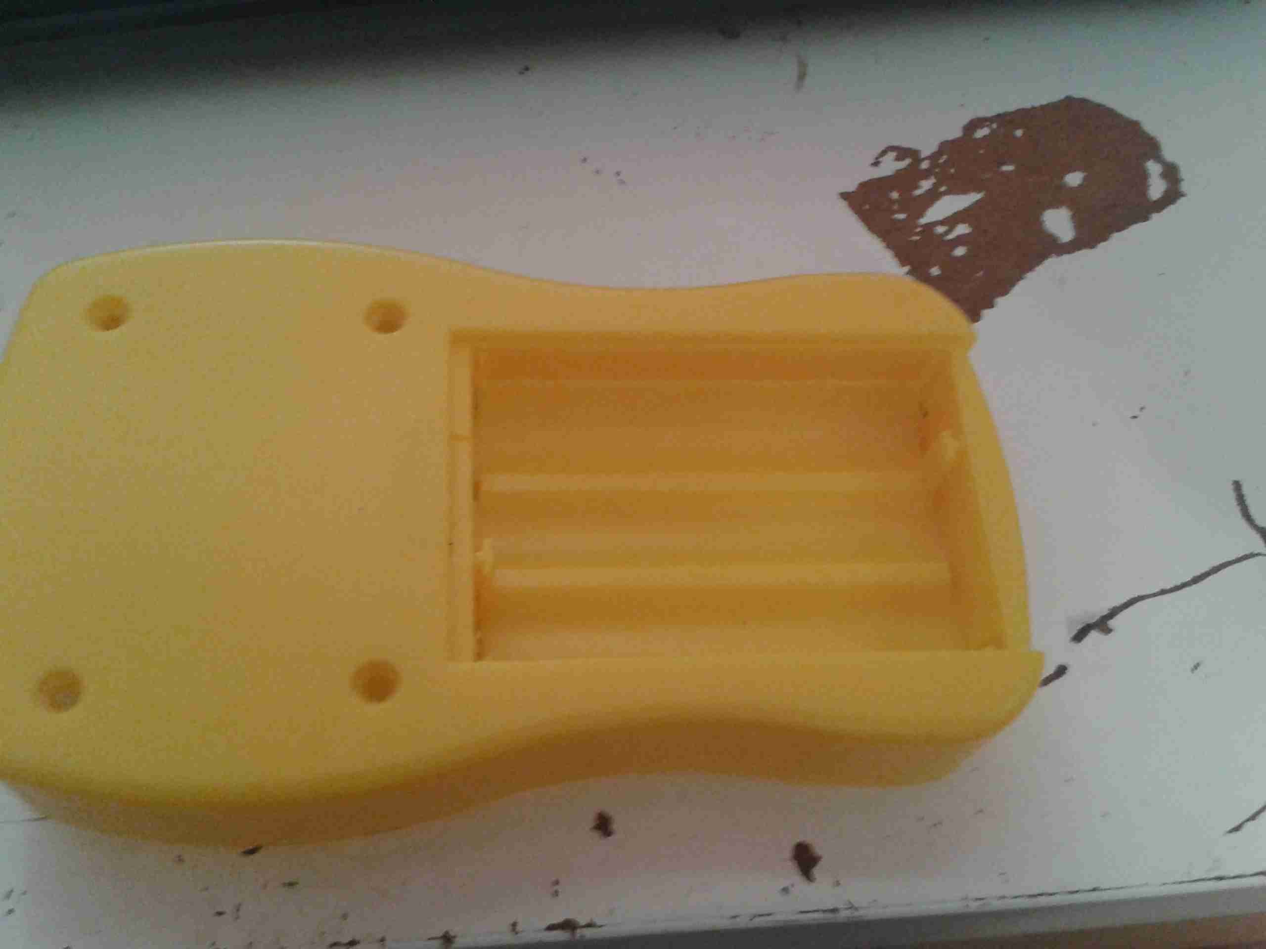
Battery Compartment
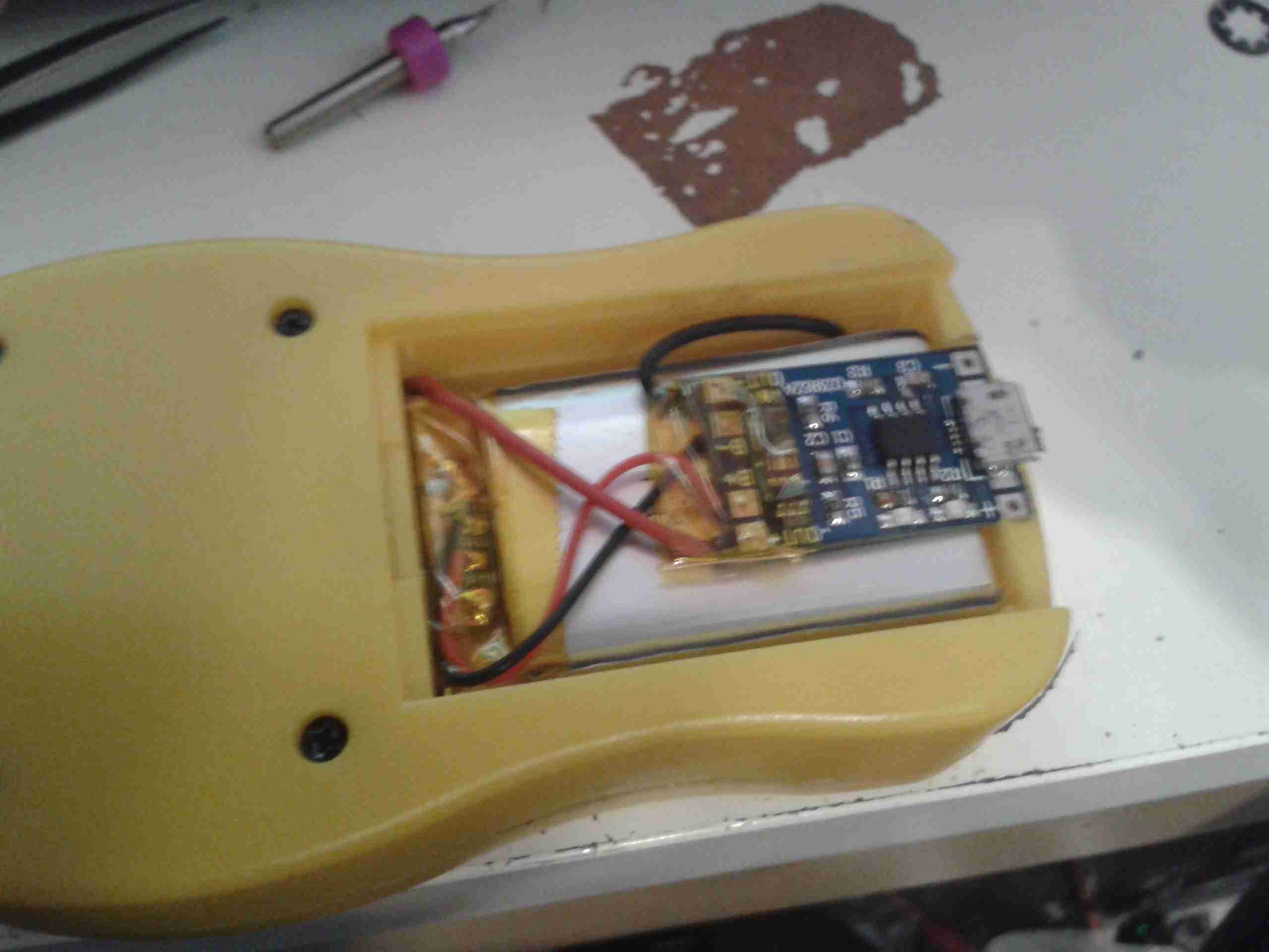
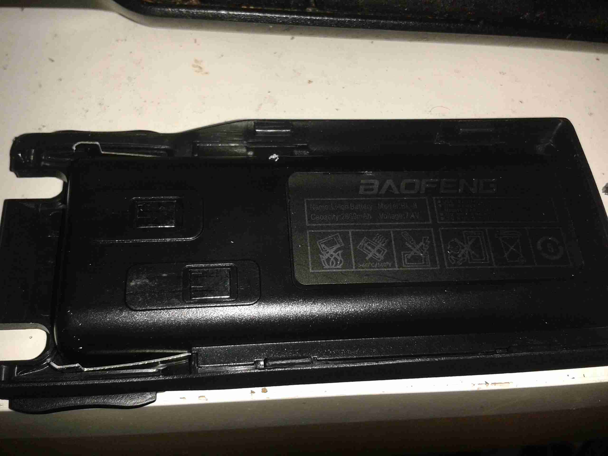
Here’s the battery compartment, with the original spring terminals removed.
I searched eBay for a suitable sized cell, and settled on a 1000mAh type, with dimensions of 47mm x 28mm x 7mm.
This size cell required a small amount of modification to the battery compartment to make it fit properly with the associated charge & protection circuitry.
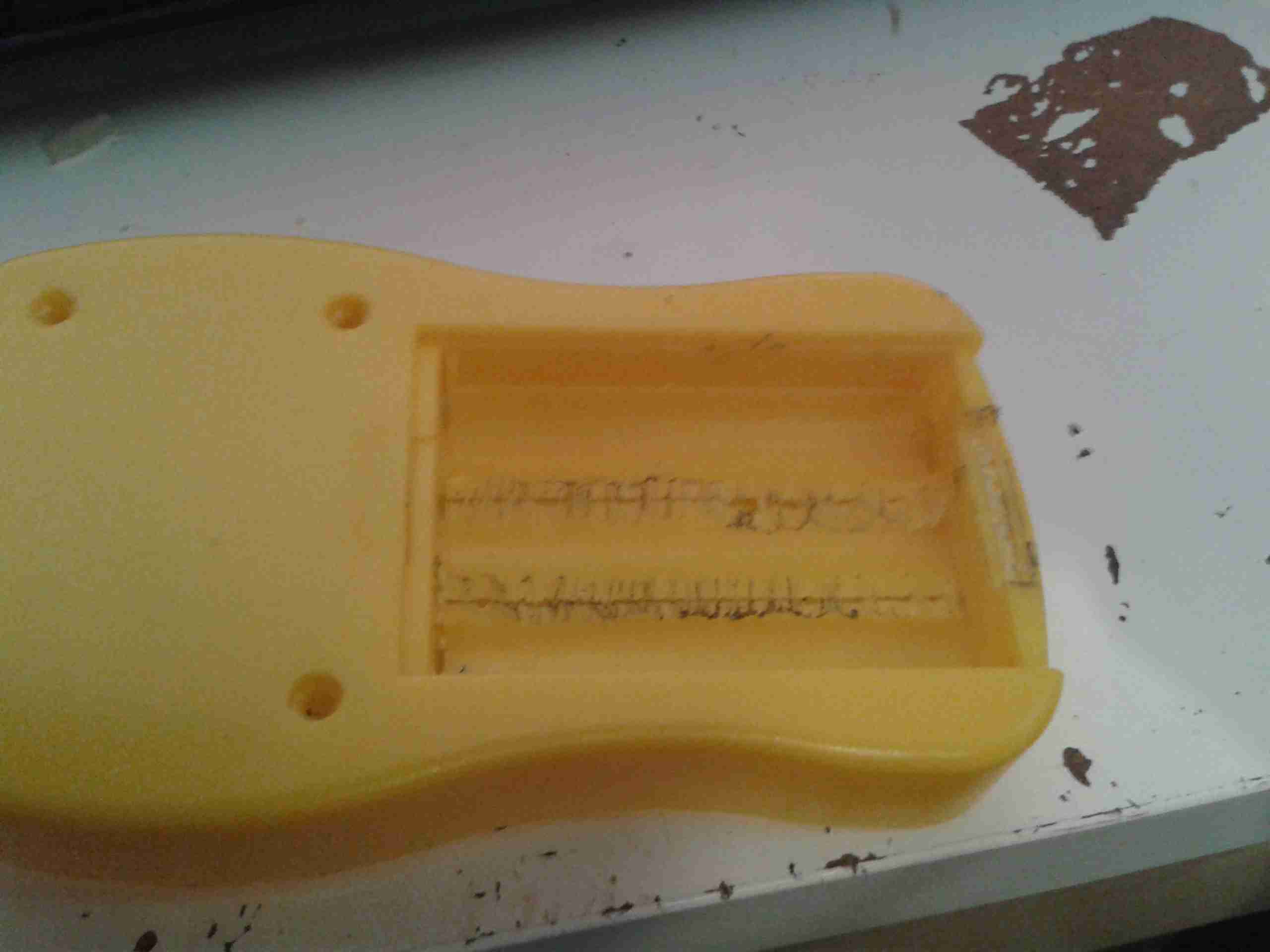
Modified Compartment
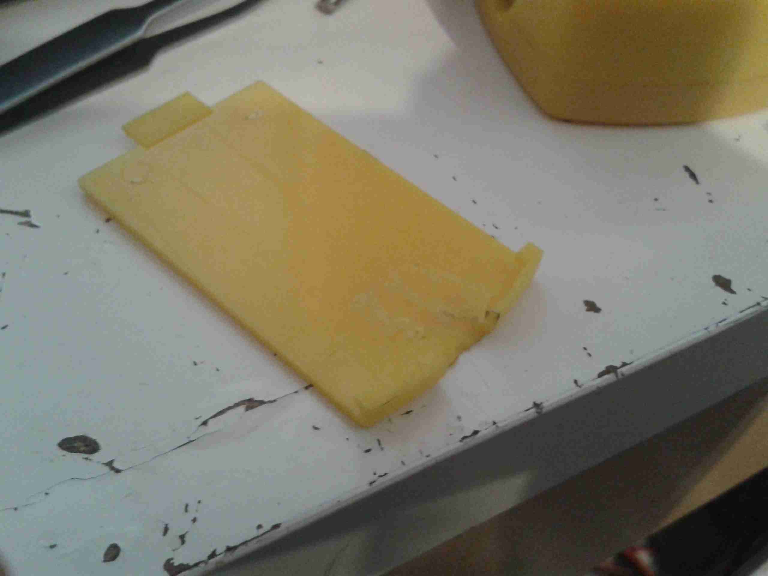
Here’s the modifications made to the compartment, I’ve ground away the plastic to make the bottom flat, and the plastic tabs that retained the original spring terminals.
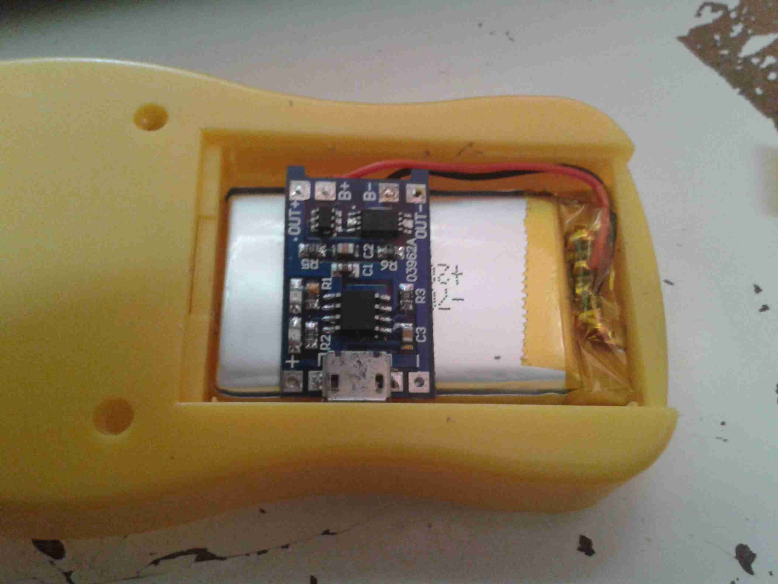
Modifications
After grinding away the original battery spring holders with a dremel, the cell fits perfectly in the available space. The small PCB on the top of the cell is the USB charger & protection.
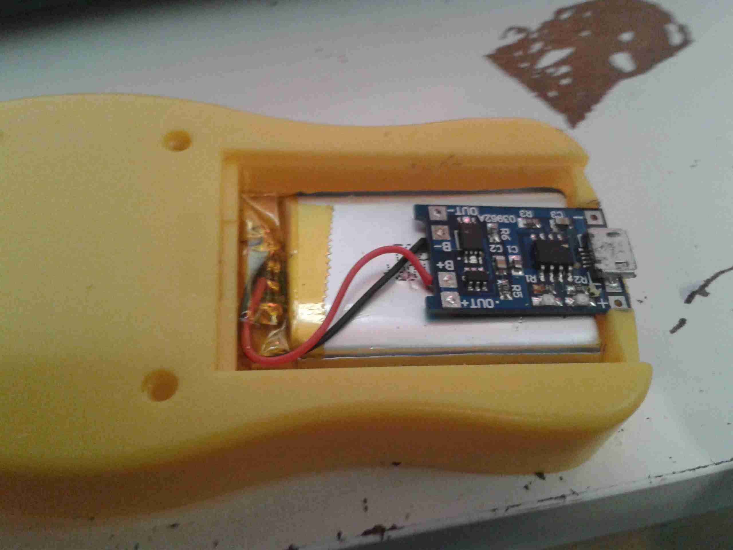
Charger
The charger is located in a slot cut in the bottom of the casing, so the USB port is accessible from outside the compartment.
Wiring
Here’s the rest of the wiring completed, with the power wires going through holes in the bottom of the battery compartment to join onto the PCB where the original terminals were located. I have insulated the solder joints on the control PCB with some Kapton tape to prevent any shorts against the lithium cell.
Battery Cover
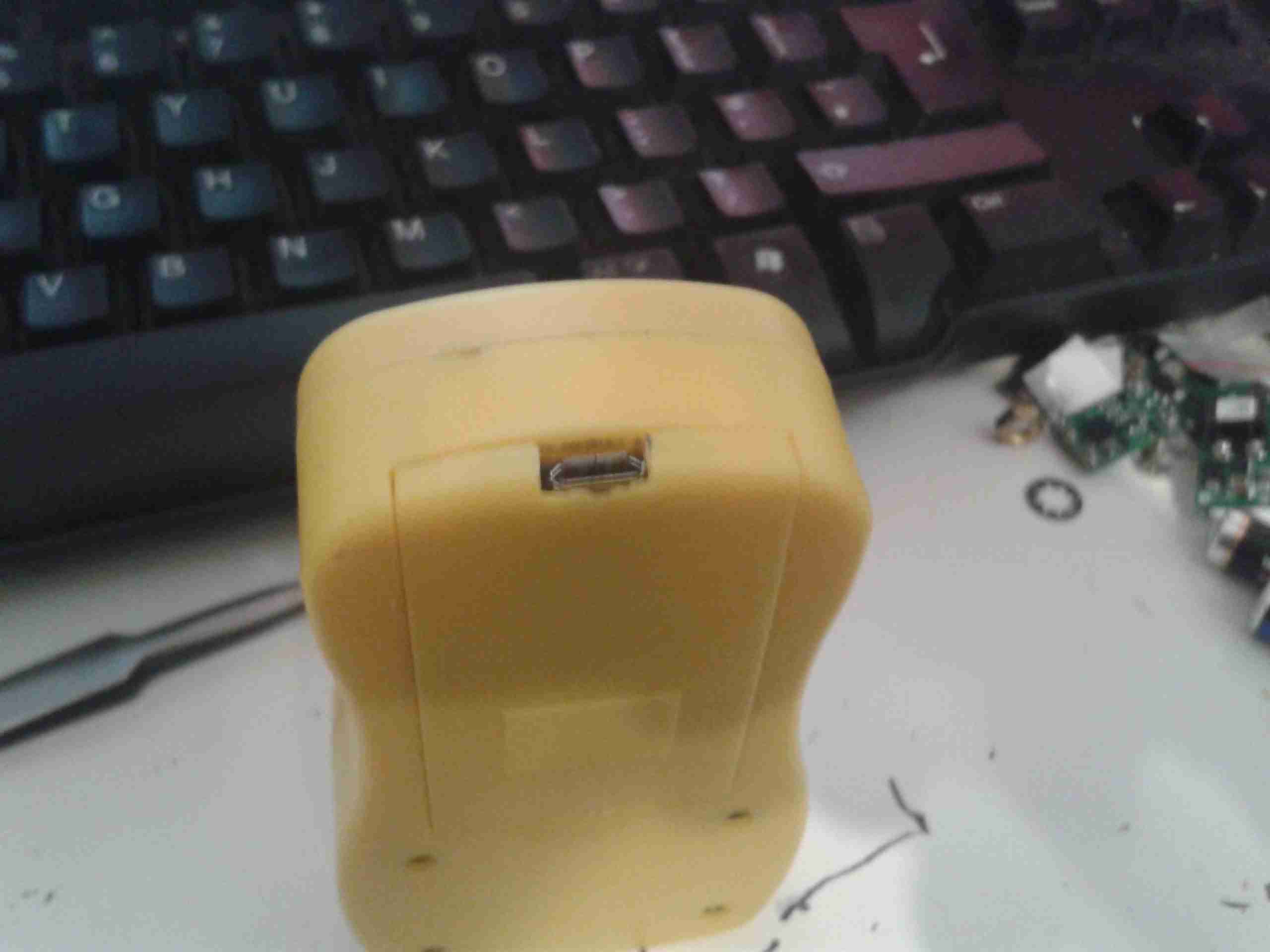
A small cutout was also required in the battery cover to allow the USB connector to poke out. This was easy to do on the soft plastic with a Dremel tool.
Charging Port
With the battery cover installed, the USB port is nicely recessed into the edge.
Charging LED
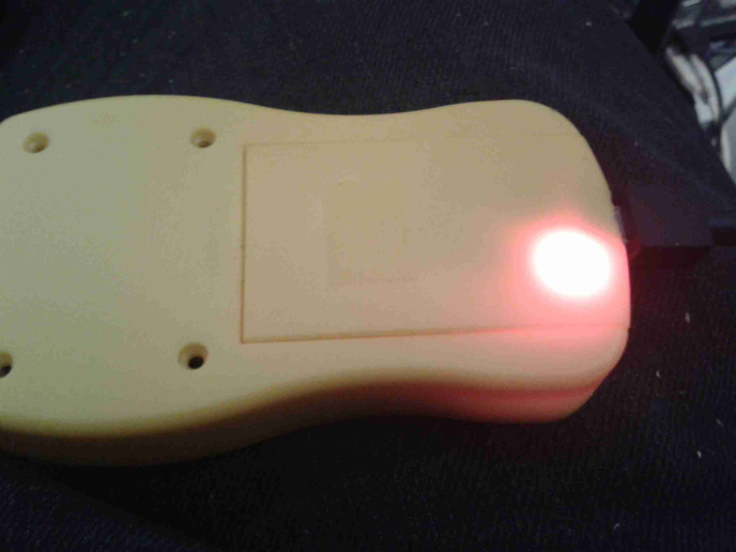
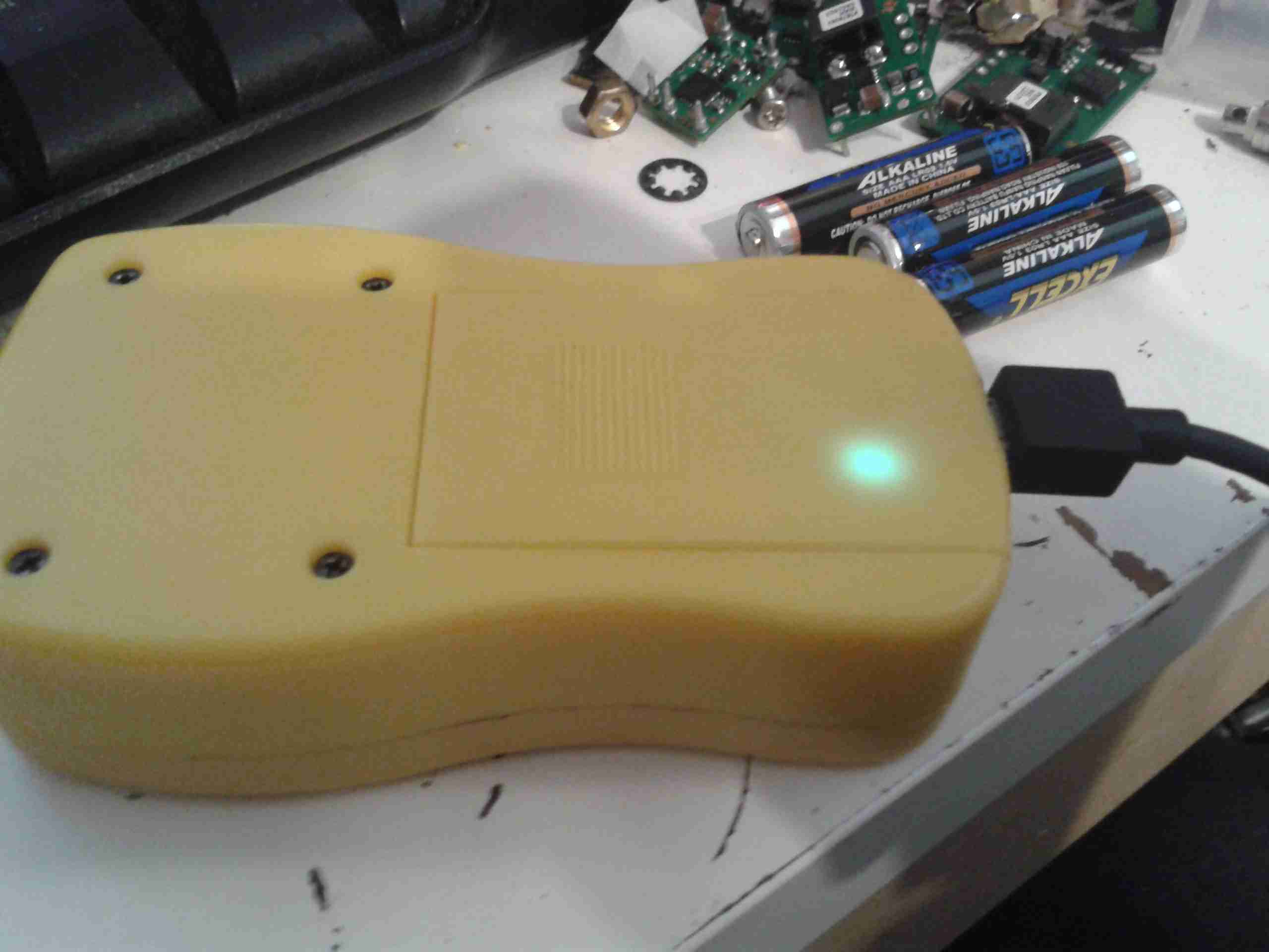
The indicator LEDs on the charging & control board show nicely through the plastic, here’s the unit on charge. When the charge is complete, another LED lights as shown below.
Since everything in my shack is run from 12v, I thought it would be handy to convert my new scope to 12v as well, as 99% of the places I find myself needing test gear are off grid, with no access to mains supplies.
Mains PSU
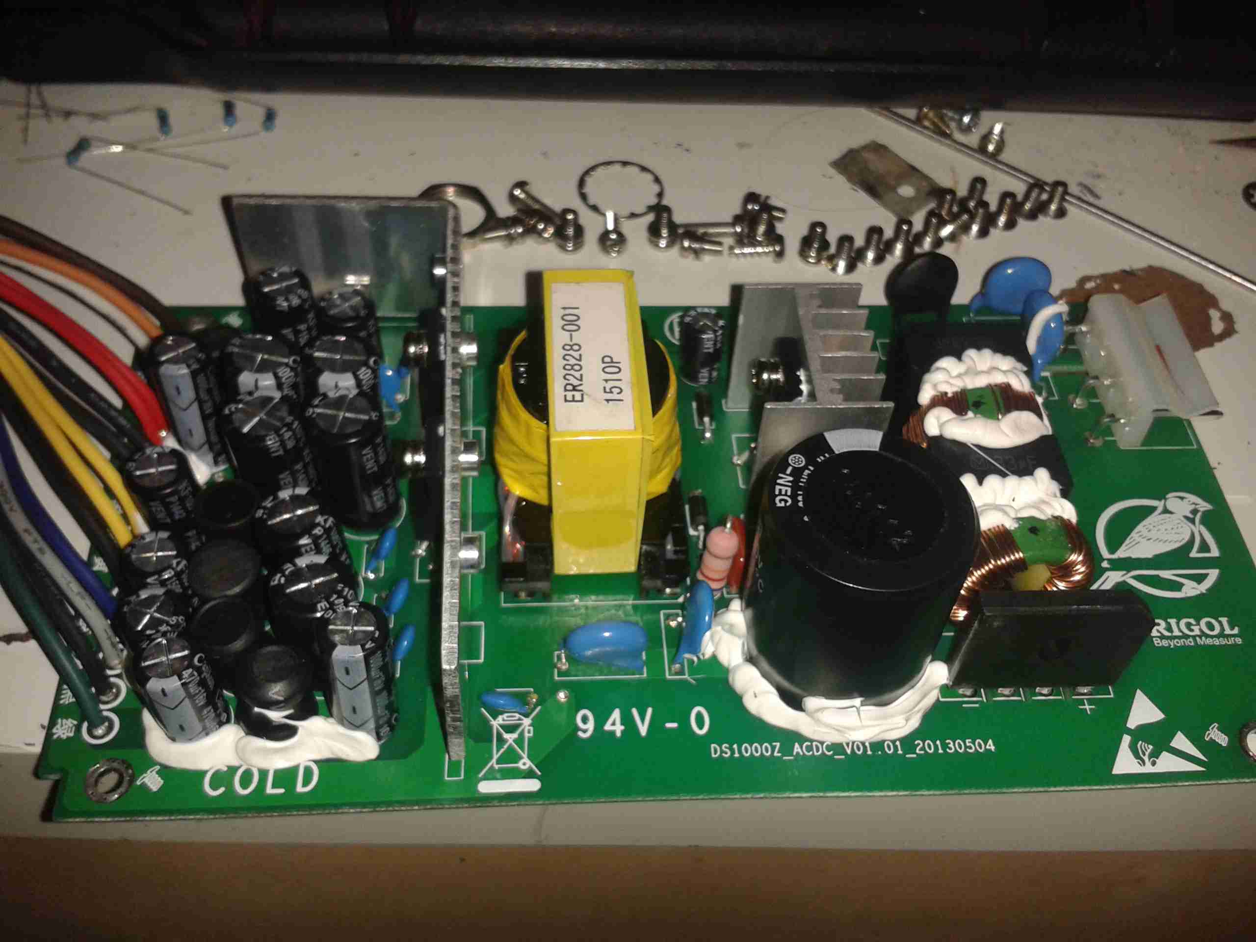
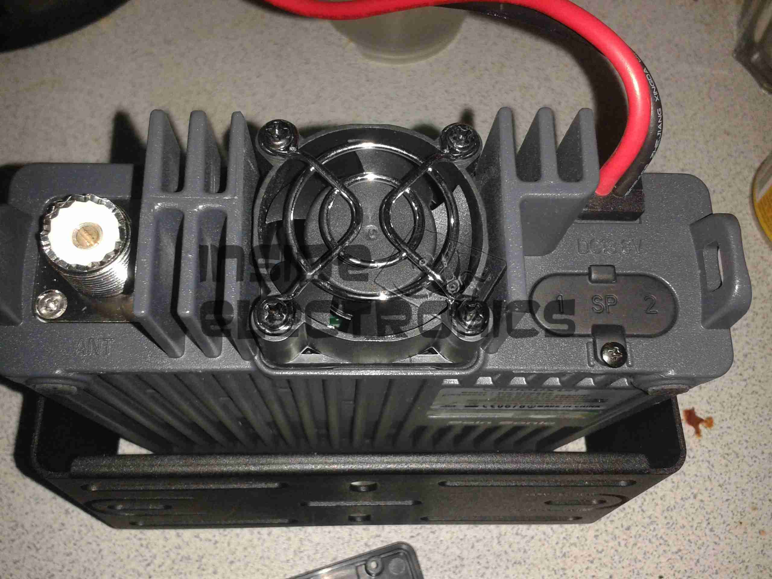
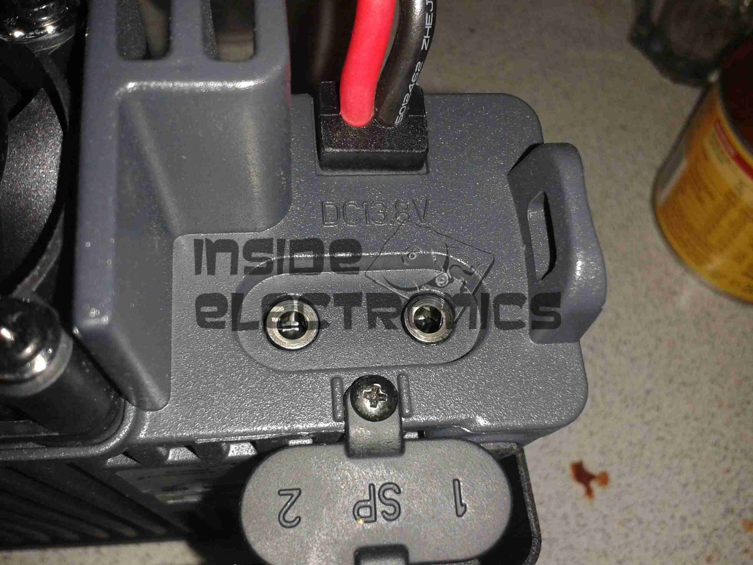
Here’s the factory mains SMPS unit from the back of the scope. This is a nice multi-rail unit, with several different outputs, the table below details the wiring of the PSU.
Connector Pin
PCB Pin
Signal
Measured Voltage
Mainboard
Rectifier Rating
Wire Colour
5
1
AC_TRIG
N/A
AC_TRIG
N/A
BROWN
2
2
+9v_GND
N/A
FAN --
NA
ORANGE
11
3
+9V
10.16V
FAN +
2A
WHITE
6
4
+5V
5.1V
5V5A
20A
RED
13
5
+5V
5.1V
5V5A
20A
RED
7
6
GND
N/A
GND
N/A
BLACK
8
7
GND
N/A
GND
N/A
BLACK
3
8
+7.5V
6.9V
6.3V
20A
YELLOW
10
9
+7.5V
6.9V
6.3V
20A
YELLOW
1
10
GND
N/A
GND
N/A
BLACK
12
11
17.5V
17.51V
17.5V
2A
BLUE
9
12
-17.5V
-17.36V
-17.5V
2A
GREY
14
13
GND
N/A
GND
N/A
BLACK
4
14
-7.5V
-6.84V
-7.5V
2A
GREEN
The only feature I will lose if I make this switch is AC line triggering, but I never use that anyway, so it’s not a big issue for me.
Since I have been able to locate the connector, the plan is to design a replacement low voltage supply unit for the scope, with the same footprint as the original AC mains supply. This will allow me to do a direct swap without causing any damage or modifying the original supply.
This method will allow me to swap the 240v supply back into the scope if I ever come to need it.
I’m planning to use the LTC3863 DC-DC Controller from Linear Tech to generate the negative rails, this will go down to -150v on the output, so it’s pretty much perfect to generate them.
PSU Output Side
Here’s the output side of the mains PSU, it has a lot of filtering on the output rails, the two TO220 devices are the output rectifiers for the +5v & +7.5v rails, these are rated at 20A, 60V.
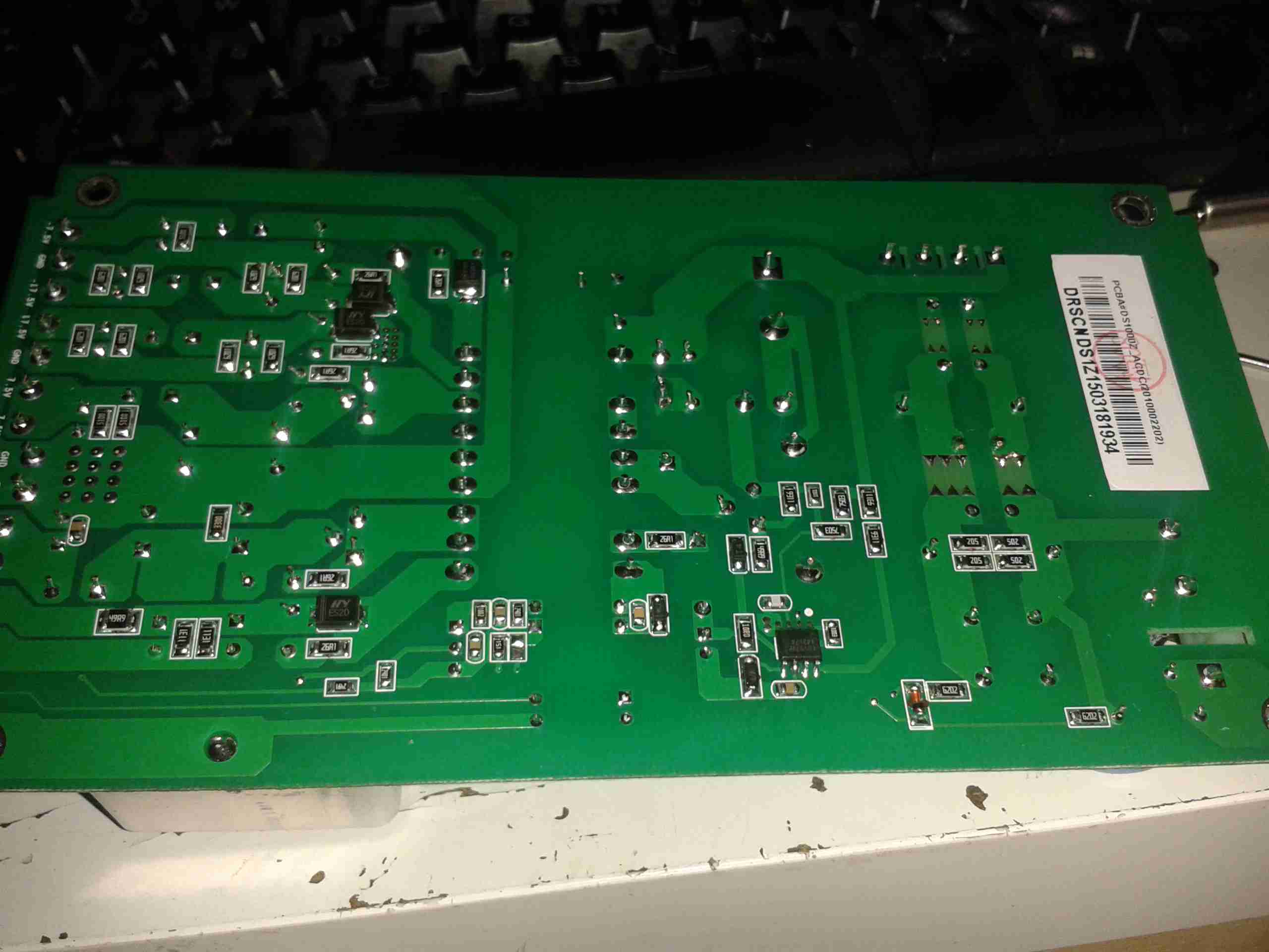
PCB Bottom
Here’s the bottom side of the PCB. It’s a really nicely designed PSU, massive isolation gap, spark gaps on the primary side & good filtering. The output side on the left has the rectifier diodes for the other voltage rails, these are only 2A rated, so designing the inverting supply to generate the negative rails will be pretty easy.
From looking at the PCB markings on both the mainboard & the PSU, the +9v rail seems to be used to drive the fan, both silkscreen markings indicate this.
The voltages marked on the PSU & the mainboard connector don’t quite match up though, there’s a small variation in the stated voltage between the two. This is most likely because all of the regulation of the supplies seems to be done on the mainboard, there are several linear regulators, and a few DC-DC switchers. Providing that the replacement supply isn’t noisy it should work fine.
This is backed up by the fact that the mains PSU only seems to regulate the +5v rail – on measuring the rails that’s the only one that’s close to spec.
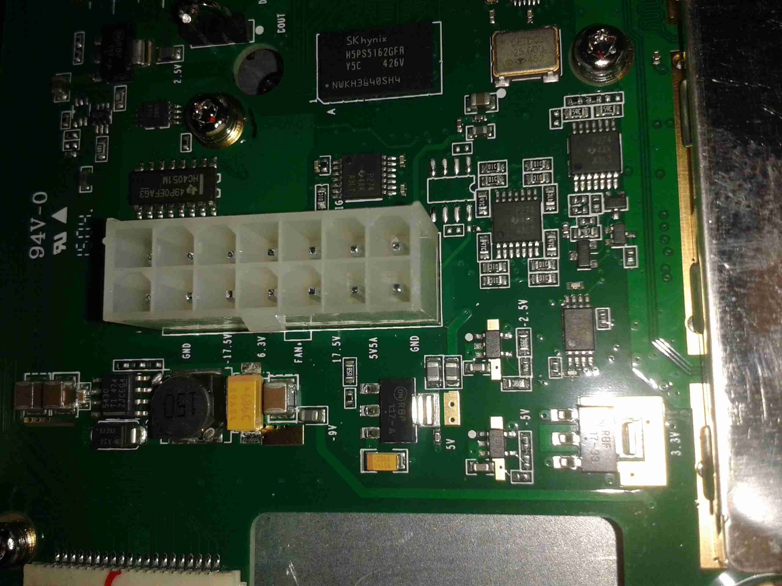
Mainboard Power
Here’s the mainboard power connector, with it’s silkscreen labelling on the pins. (Very useful). As can be seen here, there’s at least 5 regulators, of both switching & linear types here, generating both positive & negative rails.
On the boat I have installed custom LED lighting almost everywhere, but we still use CFL bulbs in a standing lamp since they have a wide light angle, and brightness for the size.
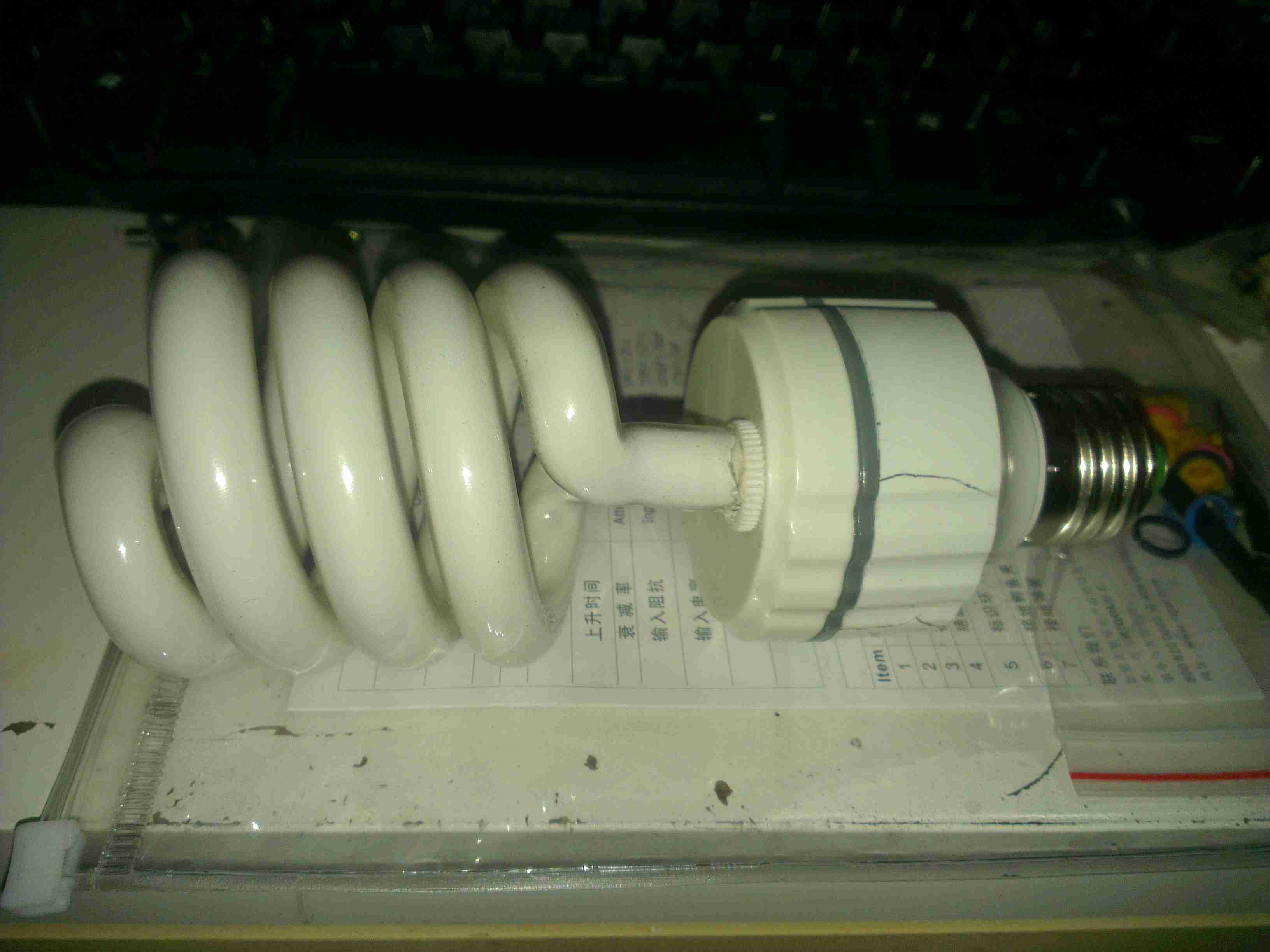
I bought a couple of 12v CFLs from China, and the first of these has been running for over a year pretty much constantly without issue. However, recently it stopped working altogether.
12v CFL
Here’s the lamp, exactly the same as the 240v mains versions, except for the design of the electronic ballast in the base. As can be seen here, the heat from the ballast has degraded the plastic of the base & it’s cracked. The tube itself is still perfectly fine, there are no dark spots around the ends caused by the electrodes sputtering over time.
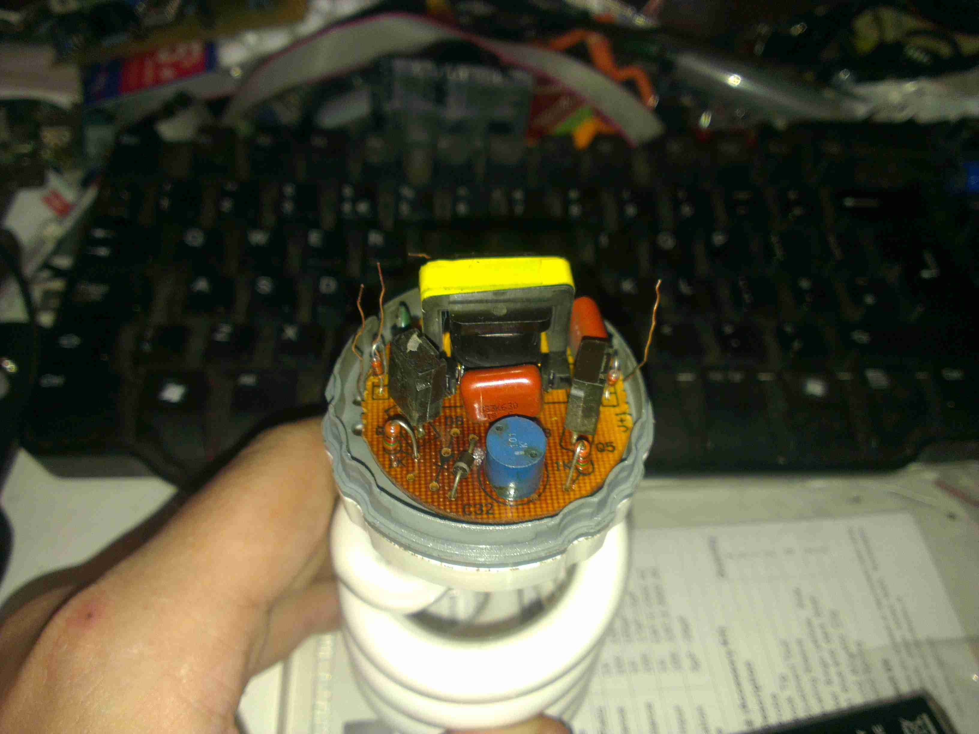
Ballast
Here’s the ballast inside the bottom of the lamp, a simple 2-transistor oscillator & transformer. The board has obviously got a bit warm, it’s very discoloured!
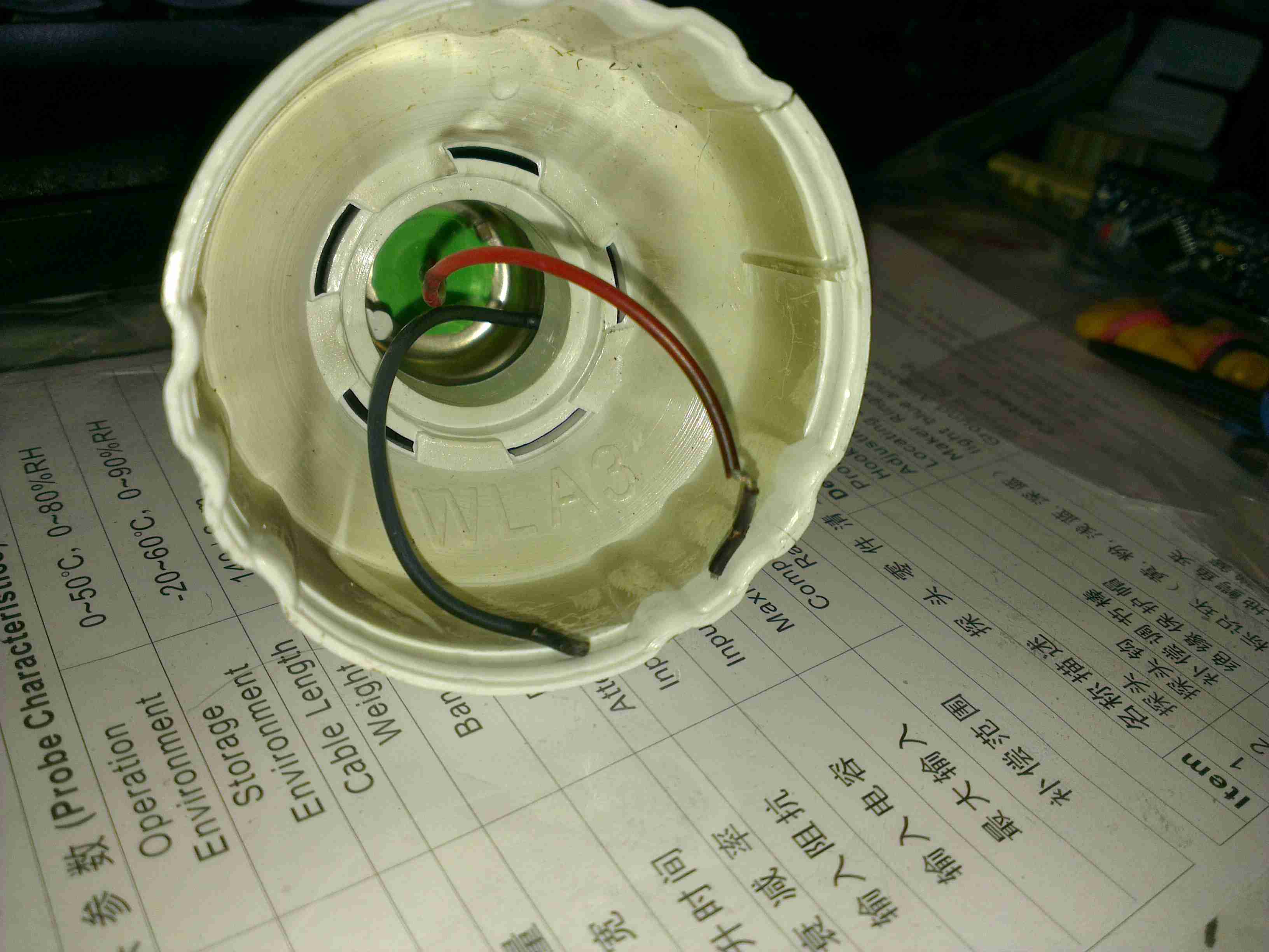
Failed Wiring
The failure mode in this case was cooked wiring to the screw base. The insulation is completely crispy!
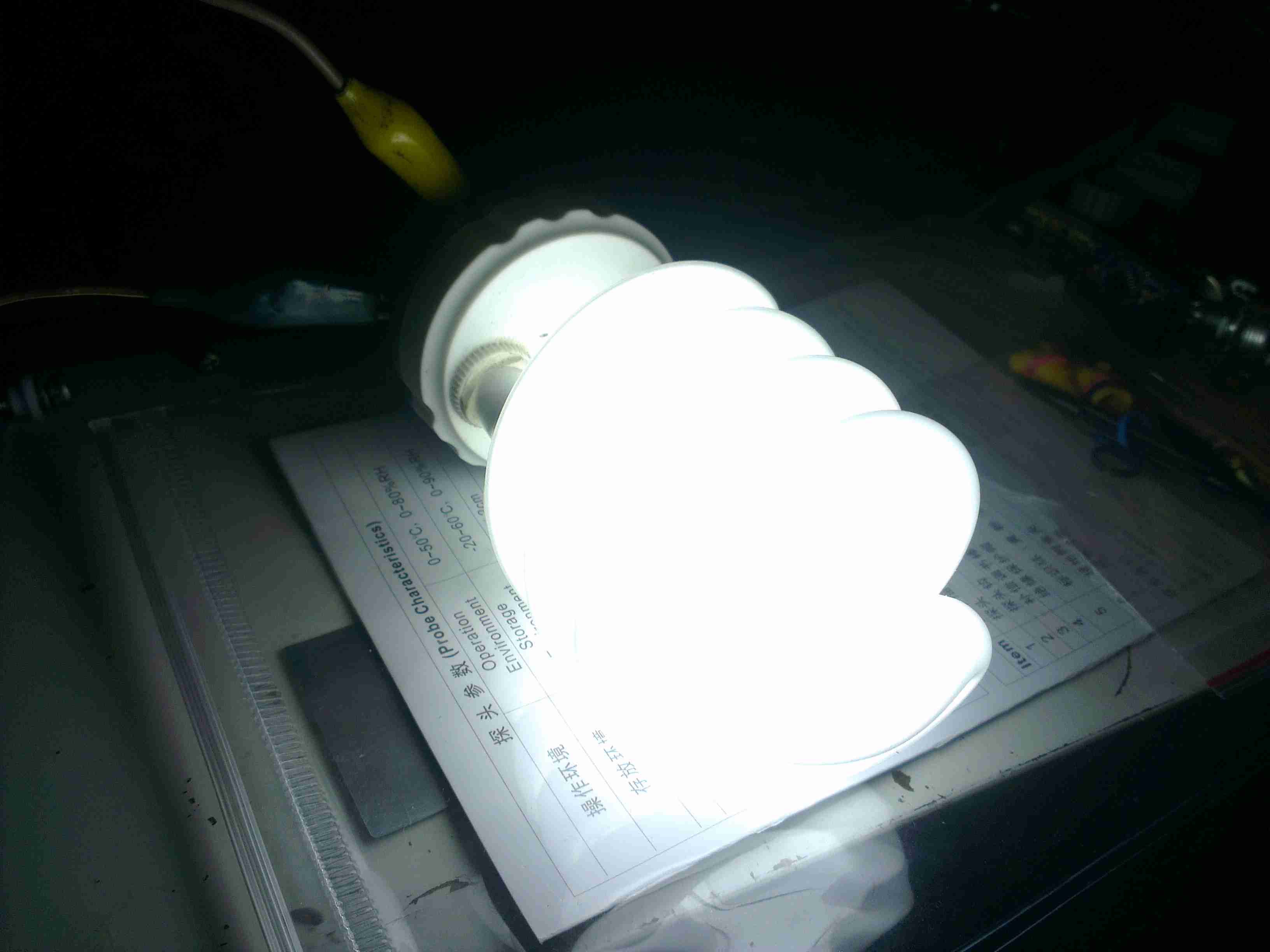
Direct Supply
On connection direct to a 12v supply, the lamp pops into life again! Current draw at 13.8v is 1.5A, giving a power consumption of 20.7W. Most of this energy is obviously being dissipated as heat in the ballast & the tube itself.
Ballast PCB
Here’s the ballast PCB removed from the case. It’s been getting very warm indeed, and the series capacitor on the left has actually cracked! It’s supposed to be 2.2nF, but it reads a bit high at 3nF. It’s a good thing there are no electrolytics in this unit, as they would have exploded long ago. There’s a choke on the DC input, probably to stop RFI, but it doesn’t have much effect.
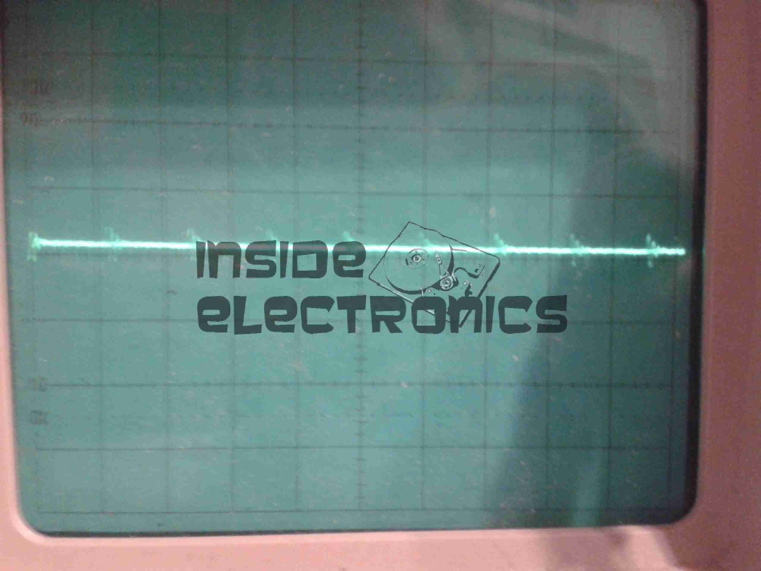
Supply Waveform
Here’s the waveform coming from the supply, a pretty crusty sinewave at 71.4kHz. The voltage at the tube is much higher than I expected while running, at 428v.
RFI
Holding the scope probe a good 12″ away from the running bulb produces this trace, which is being emitted as RFI. There’s virtually no filtering or shielding in this bulb so this is inevitable.
Here’s an odd & sudden failure, the power adaptor for a Samsung device. It’s been working for months & on being plugged into the mains today the magic blue smoke escaped.
Samsung Charger
It’s one of their 2A models, for charging bigger devices like tablets.
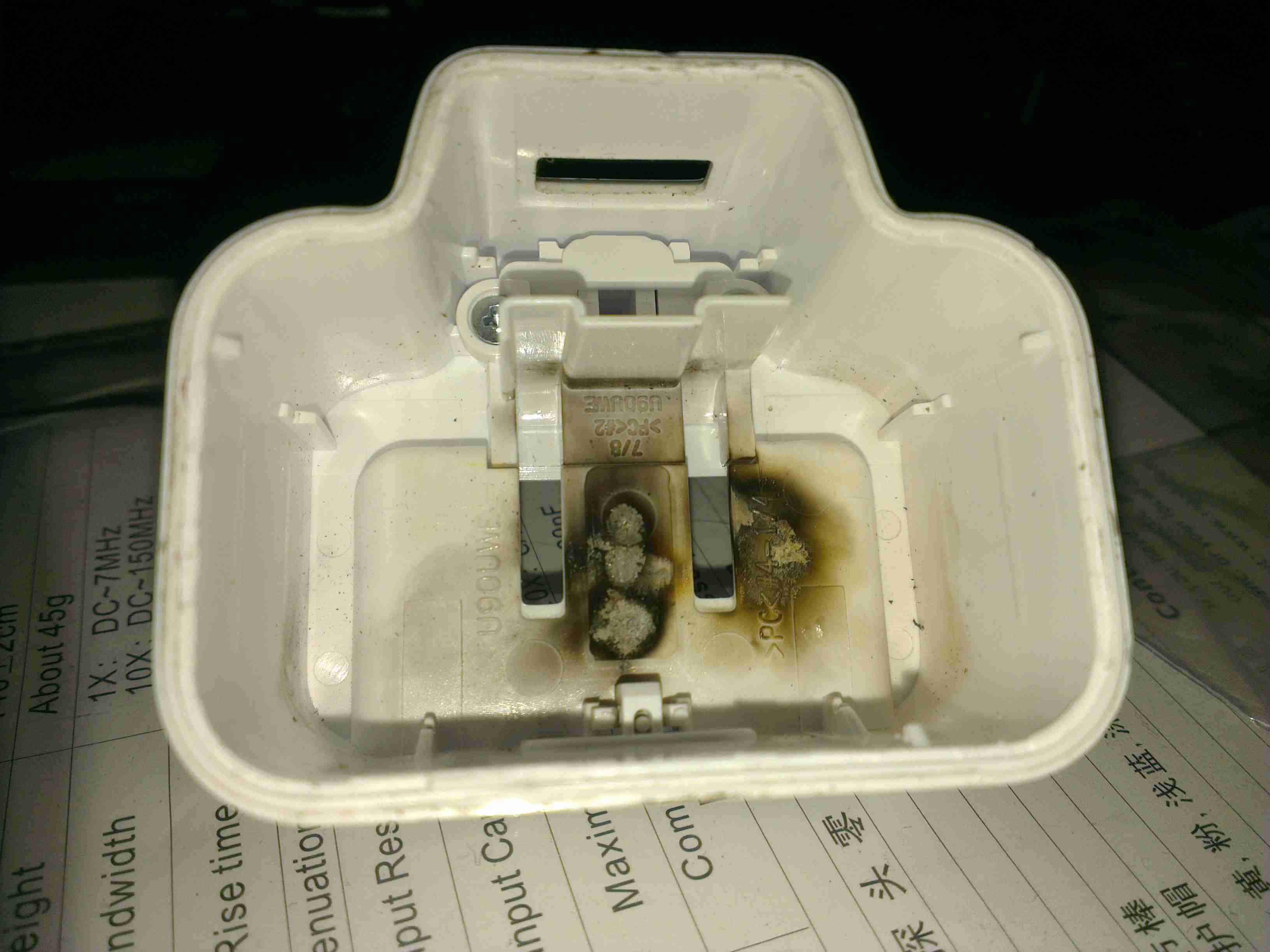
Flash Burn
Strangely for one of these chargers, no glue is used to hold it together – just clips. This made disassembly for inspection much easier. Evidence of a rather violent component failure is visible inside the back casing.
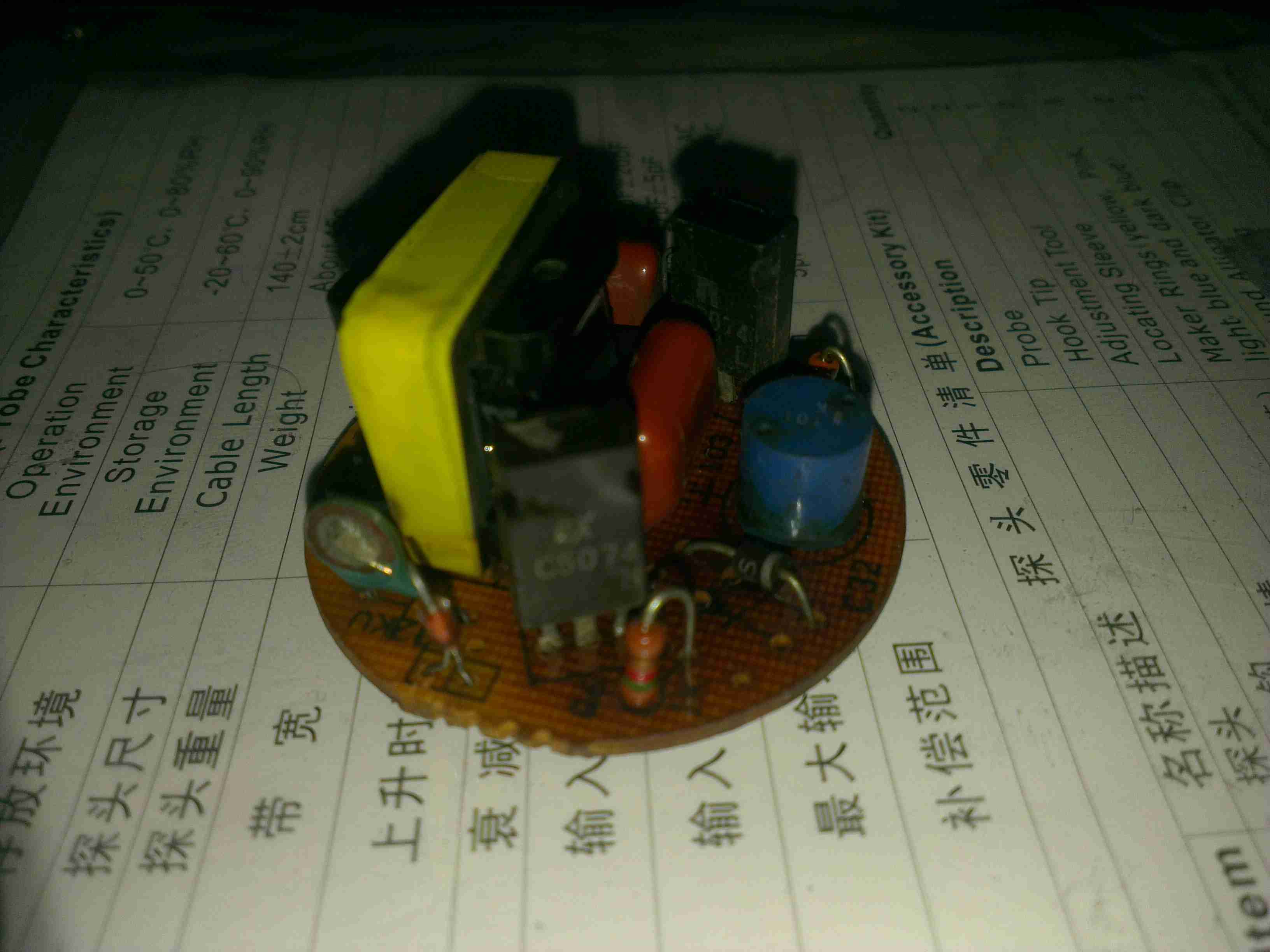
PCB
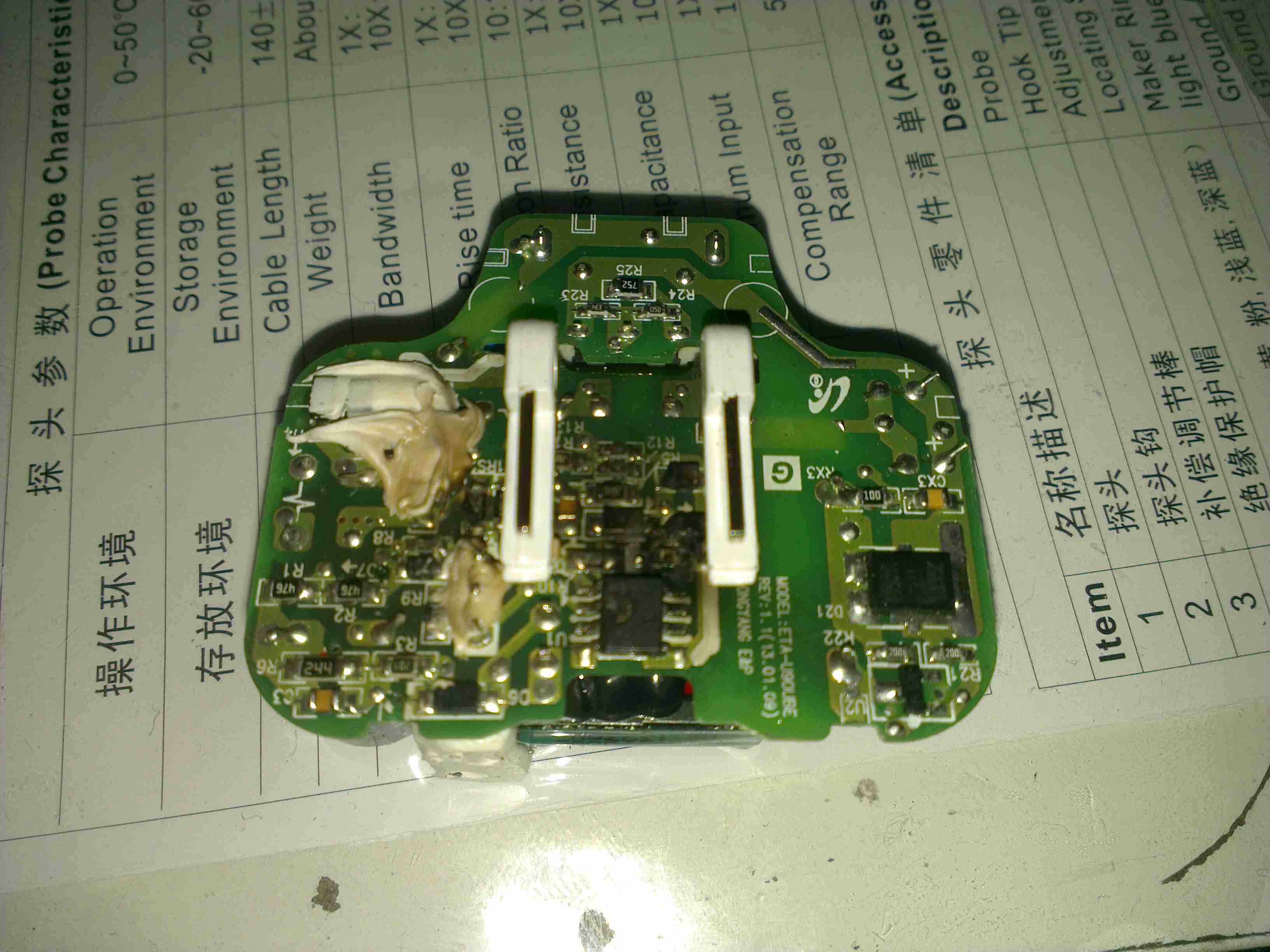
Here’s the charger PCB removed from the casing. As to be expected from Samsung, it’s a high quality unit, with all the features of a well designed SMPS.
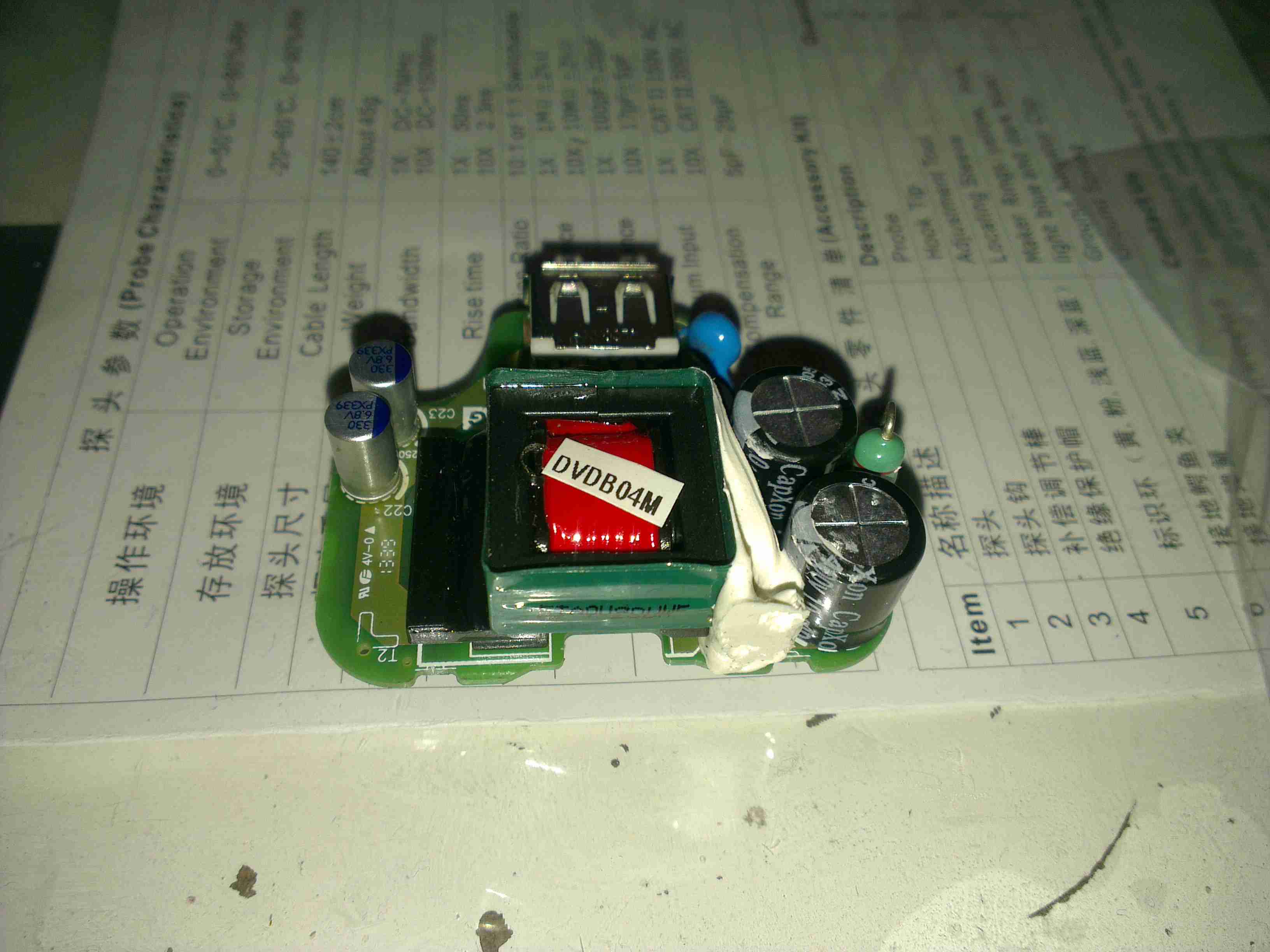
PCB Reverse
However, on turning the board over, the blown component is easily visible. It’s the main SMPS controller IC, with a massive hole blown in the top. The on board fuse has also blown open, but it obviously didn’t operate fast enough to save the circuit from further damage!
Having now tested the supply I wrote about in my previous post, I can now say that it’s nameplate rating far exceeds it’s actual capability.
On running the supply under load, at 6.5A the operating frequency drops into the audible range, a big sign of overload. (It makes an irritating continuous chirping noise). The output voltage also drops to 10.5v.
The temperature of the unit while it’s been running under such a load is also questionable, the external casing gets hot enough to cause burns, I haven’t yet been able to stick a thermocouple into the case to see what the internal temperature is.
I’m currently talking with the eBay seller (wwwstation) regarding this, however they are arguing that the supply is only for LEDs & CCTV cameras.
However those two loads are very different, and the supply has no internal regulation for supplying LEDs. As a simple switchmode supply, any load is suitable, providing it’s within the load rating of the supply.
I would estimate that the supply is only capable of 5A as an upper limit.
They are requesting that I return the supply, but I’m yet to find out if they’re going to cover return postage. The item as listed is not as described, and I will escalate things if required.
I will update this post when I hear more back from the eBay seller.
I recently dug out my other card printer to fit it with a 12v regulator, (it’s 24v at the moment), and figured I’d do a teardown post while I had the thing in bits.
This is a less industrial unit than my Zebra P330i, but unlike the Zebra, it has automatic duplexing, it doesn’t have Ethernet connectivity though.
Unlike domestic printers, which are built down to a price, these machines are very much built up to a spec, and feature some very high quality components.
Naked Printer
Here’s the mechanism with the cowling removed. This is the main drive side of the printer, with the main drive stepper at left, ribbon take-up spool motor lower right, and the duplex module stepper motors at far right.
Main Motor Drive
The main drive motor runs the various rollers in the card path through a pair of synchronous belts, shown here.
Main Stepper
The stepper itself is a quality ball-bearing Sanyo Denki bipolar motor.
Main Stepper Driver
Electrical drive is provided to the stepper with a L6258EX DMOS universal motor driver. This chip can also drive DC motors as well as steppers.
Ribbon Supply Spool
Here is the encoder geared onto the ribbon supply spool. This is used to monitor the speed the ribbon is moving relative to the card.
Printer Top
Here’s a top view through the printer, the blue roller on the left cleans the card as it’s pulled from the feeder, the gold coloured spool to it’s right is the ribbon supply reel. The cooling fan on the right serves to stop the print head overheating during heavy use.
Spool Take Up Motor
The spool take-up reel is powered by another very high quality motor, a Buhler DC gearmotor. These printers are very heavily over engineered!
This motor drives the spool through an O-Ring belt, before the gear above. This allows the drive to slip in the event the ribbon jams, preventing it from breaking.
Duplex Unit Stepper Drivers
The pair of steppers that operate the duplexing unit are driven by a separate board, with a pair of L6219DS bipolar stepper driver ICs. There are also a couple of opto-sensors on this board for the output hopper.
Main Control PCB
All the mechanisms of the printer are controlled from this main PCB, which handles all logic & power supply functions. Sections on the board are unpopulated, these would be for the Ethernet interface, smart card programming & magstripe programming.
Main CPU
The brains of the operation is this ColdFire MCF5208CVM166 32-bit microprocessor. It features 16KB of RAM, 8KB of cache, DMA controller, 3 UARTs, SPI, 10/100M Ethernet and low power management. This is a fairly powerful processor, running at 166MHz.
It’s paired with an external 128Mbit SDRAM from Samsung, and a Spansion 8Mbit boot sector flash, for firmware storage.
USB Interface & Power Input
Here the USB interface IC is located. It’s a USBN9604 from Texas Instruments, this interfaces with the main CPU via serial.
In my shack, 99% of my gear is all 12v powered, which is good for a few reasons:
Single Power Supply – This increases efficiency, as I’m only getting the losses of a single supply.
Safety – Mains voltages are dangerous, I’m not fond of working on such equipment.
Portability – I can power everything pretty much no matter were I am from a convenient car battery.
Convenience – Since everything is single supply, with all the same plugs, I don’t have to think about what goes where. This is more important due to my forgetfulness ;).
The one piece of equipment I regularly use that isn’t 12v is my soldering station. This is a Maplin A55KJ digital unit, which uses a 24v heating element.
While the soldering wand works OK when hooked direct to a 12v power supply (only at half power though), this removes the convenience of having temperature control.
The circuitry inside the unit is PIC microcontroller based, and doesn’t even bother rectifying the AC from the supply transformer before it’s sent to the heater. Because of this there are several reasons why I can’t just hook a DC-DC converter up to it to give it 24v.
It’s sensing the zero-crossing for the triac switch, to reduce heat dissipation, so it refuses to work at all with DC.
On looking at the Great Google, I found a project on Dangerous Prototypes, an Arduino based PID controller for soldering irons.
This requires that the soldering wand itself contains a thermocouple sensor – as the Maplin one I have is a cheap copy of the Atten 938D, it doesn’t actually use a thermocouple for temperature sensing. It appears to read the resistance of the element itself – Nichrome heating elements change resistance significantly depending on temperature.
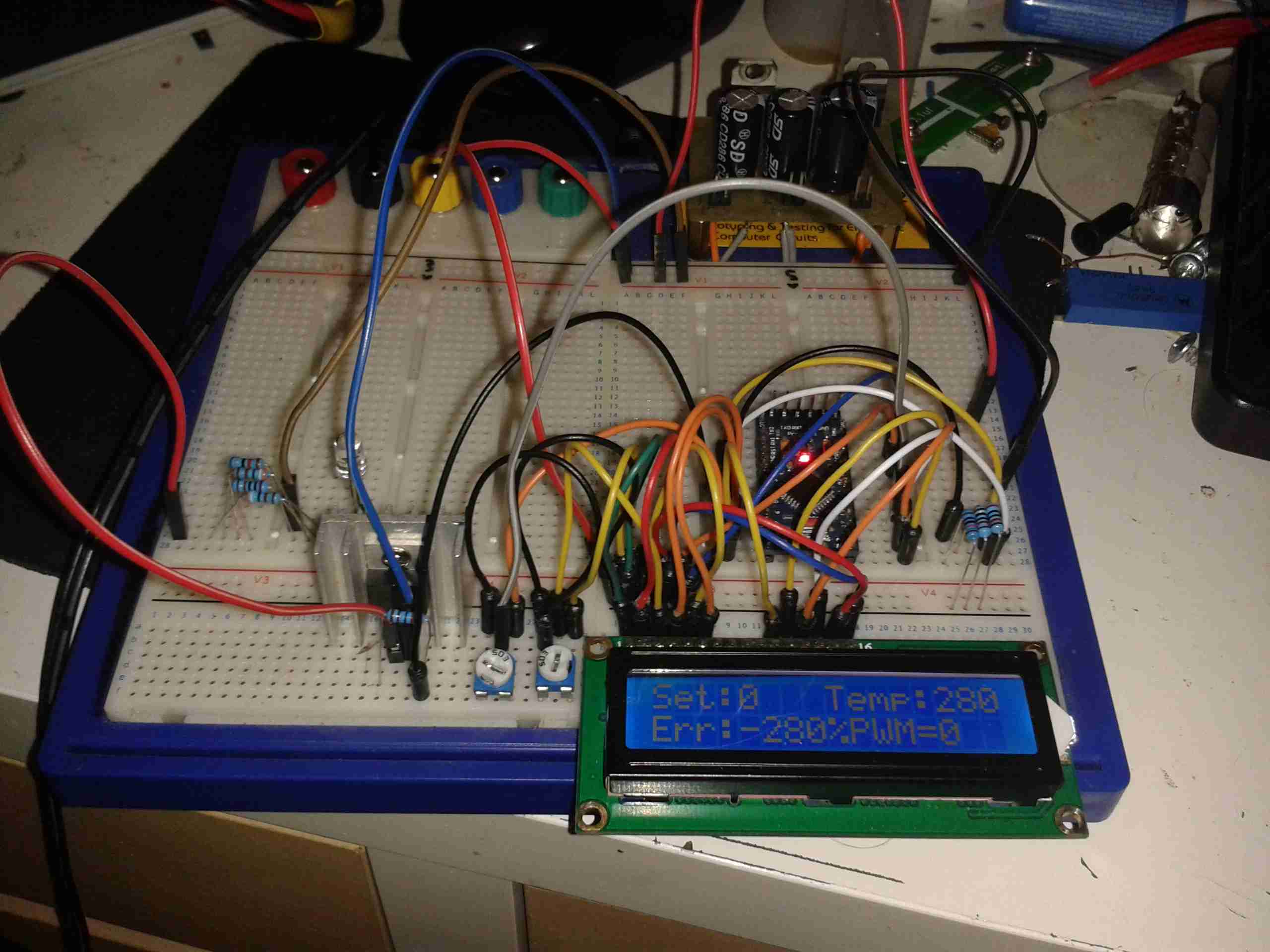
I’ve managed to find a source of cheap irons on eBay, with built in thermocouples, so I’ve got a couple on order to do some testing with. While I wait for those to arrive, I’ve prototyped up the circuit on breadboard for testing:
Prototype
I’ve remapped some of the Arduino pins, to make PCB layout less of a headache, but the system is working OK so far, with manual input for the sensed temperature.
I’m using an IRL520N logic-level HEXFET for the power switching, rated at 10A. As the irons only draw a max of 4.5A, this is plenty beefy enough.
To come up with the +24v supply for the heater, a small DC-DC converter will be used.
More to come when the components for the thermocouple amplifier arrive, and the soldering irons themselves!
Thanks to Lewis over at Distant Signal Radio, the bad influence he is on my bank balance ;), I’m the proud new owner of a new Baofeng. This time it’s the UV-82.
This radio is a little different from the other Baofengs I have. Here are the main differences:
Dual PTT – This one is going to take some getting used to 😉
Higher capacity battery pack
A more rugged, commercial feel
This radio has a different method of selecting the VFO mode – holding the menu key while the unit is powered on. This is a little awkward, but since I only usually use my local repeaters when I’m mobile, it’s not much of an issue.
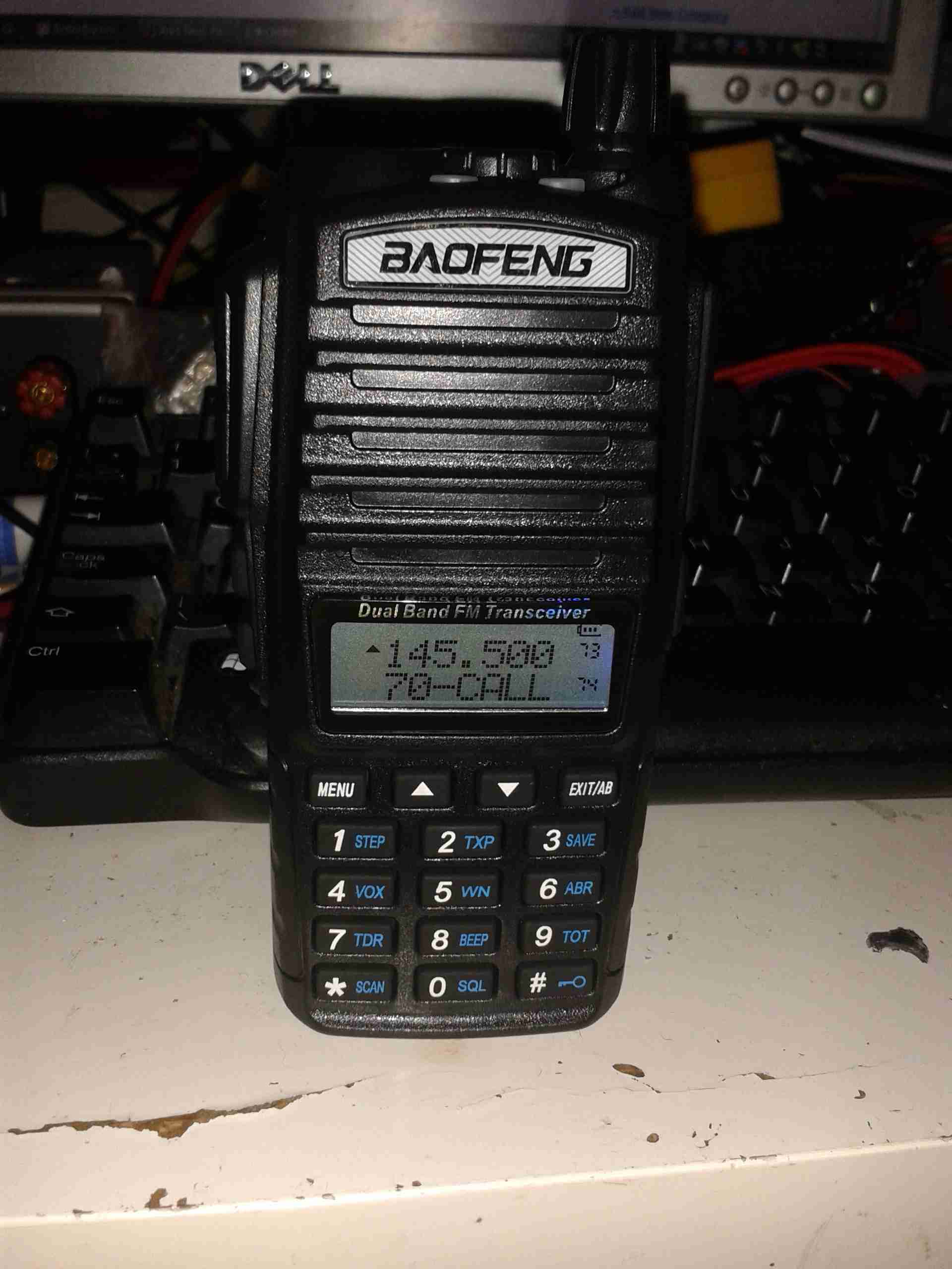
UV-82
Here’s the radio itself, it has a much more commercial feel to it than the UV-5Rs, and it’s slightly bigger. Mainly due to the use of a larger standard battery & larger loudspeaker.
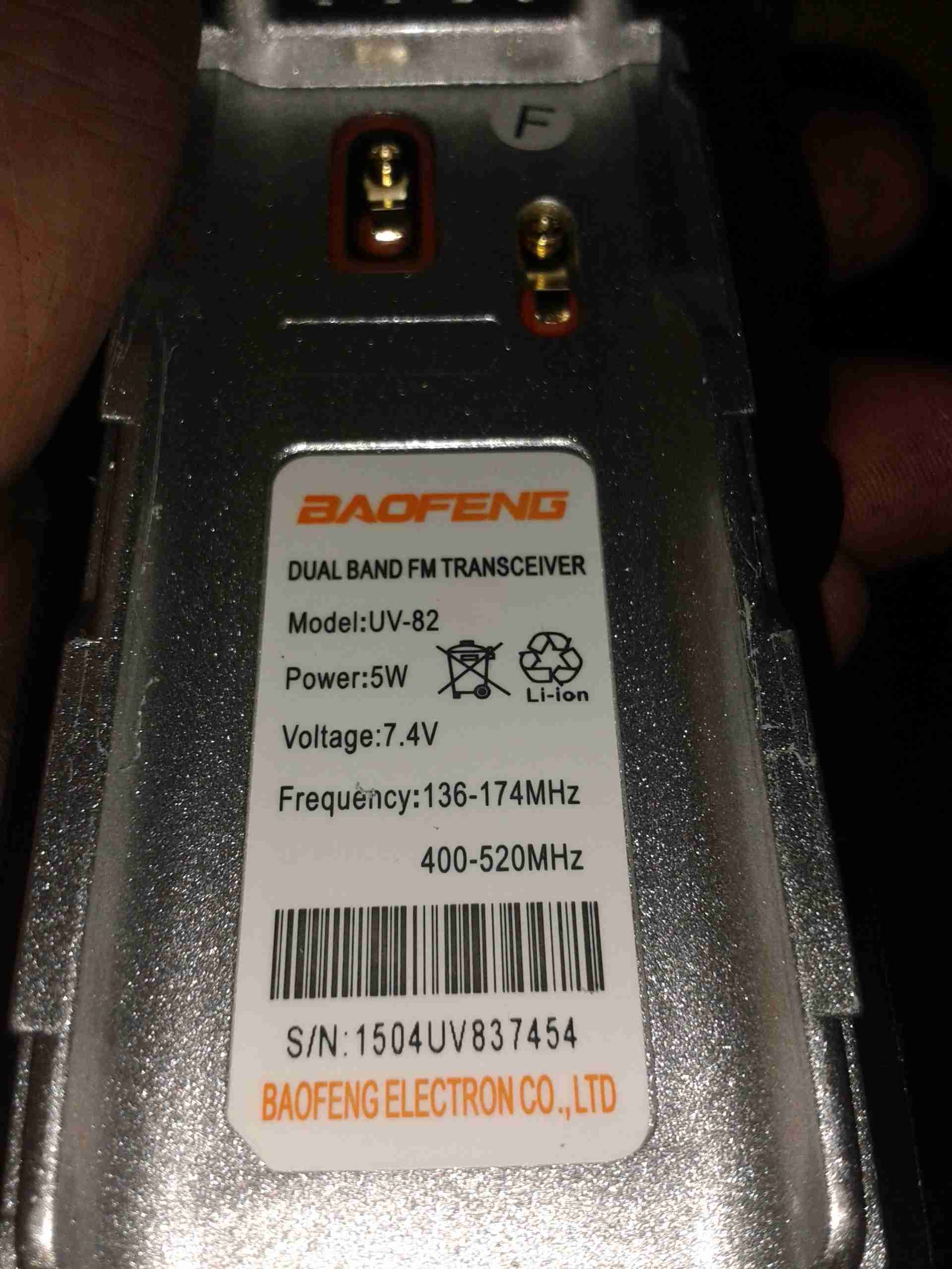
Spec Label
Back of the unit with the spec label. As per usual Baofeng are a bit conservative with the power ratings, more to come on that below.
Battery Pack
Here’s the battery pack, a 2-cell lithium-polymer unit. This has a bigger capacity than the standard UV-5R battery, at 2800mAh.
Here are the power settings as measured by my GY-561. Frequencies used are 145.500 & 433.500
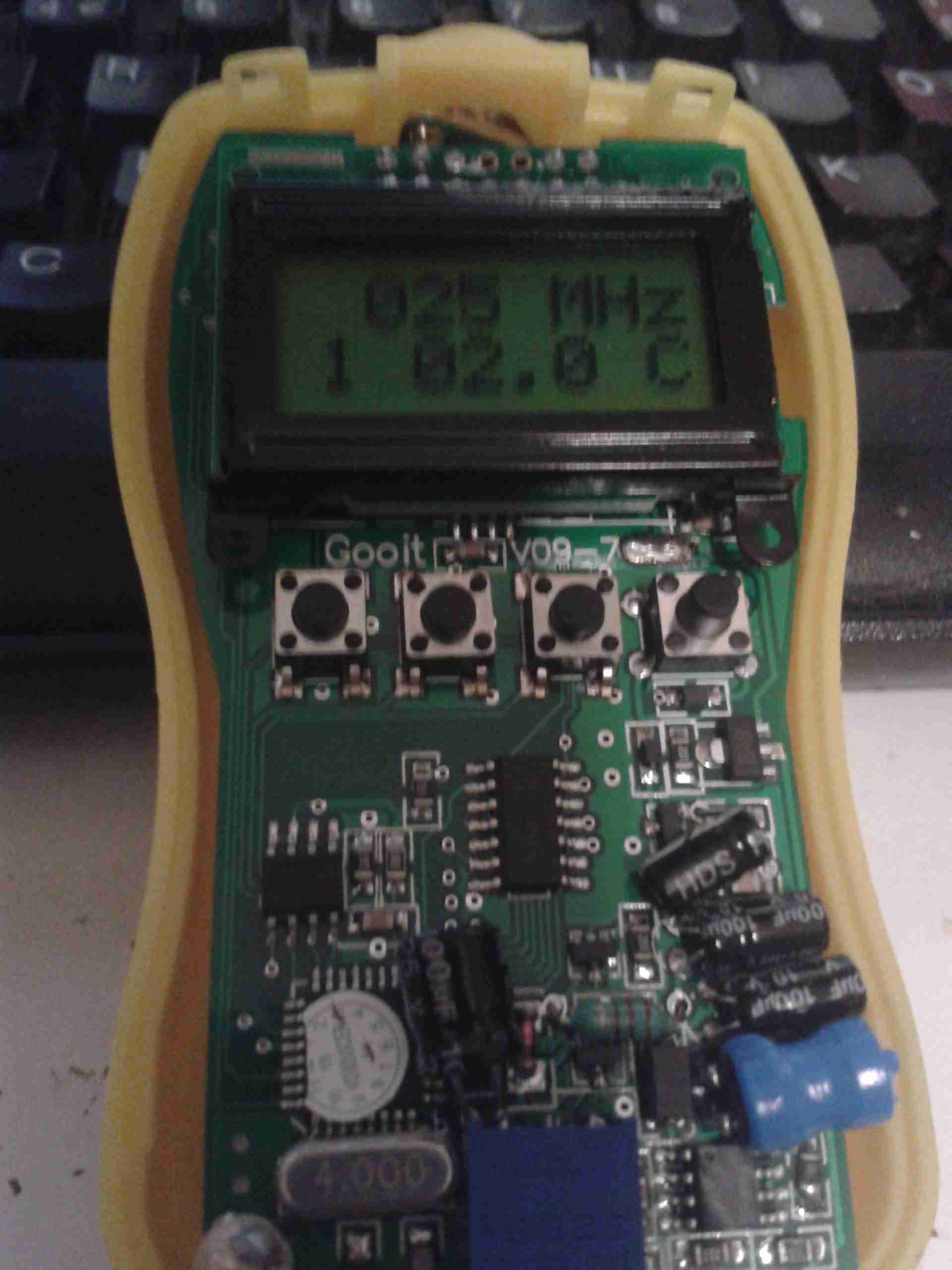
Unfortunately the manual for the eBay GY561 Frequency & RF Power Meter is very badly translated, but I think I have figured out the calibration procedure, so here it goes 🙂
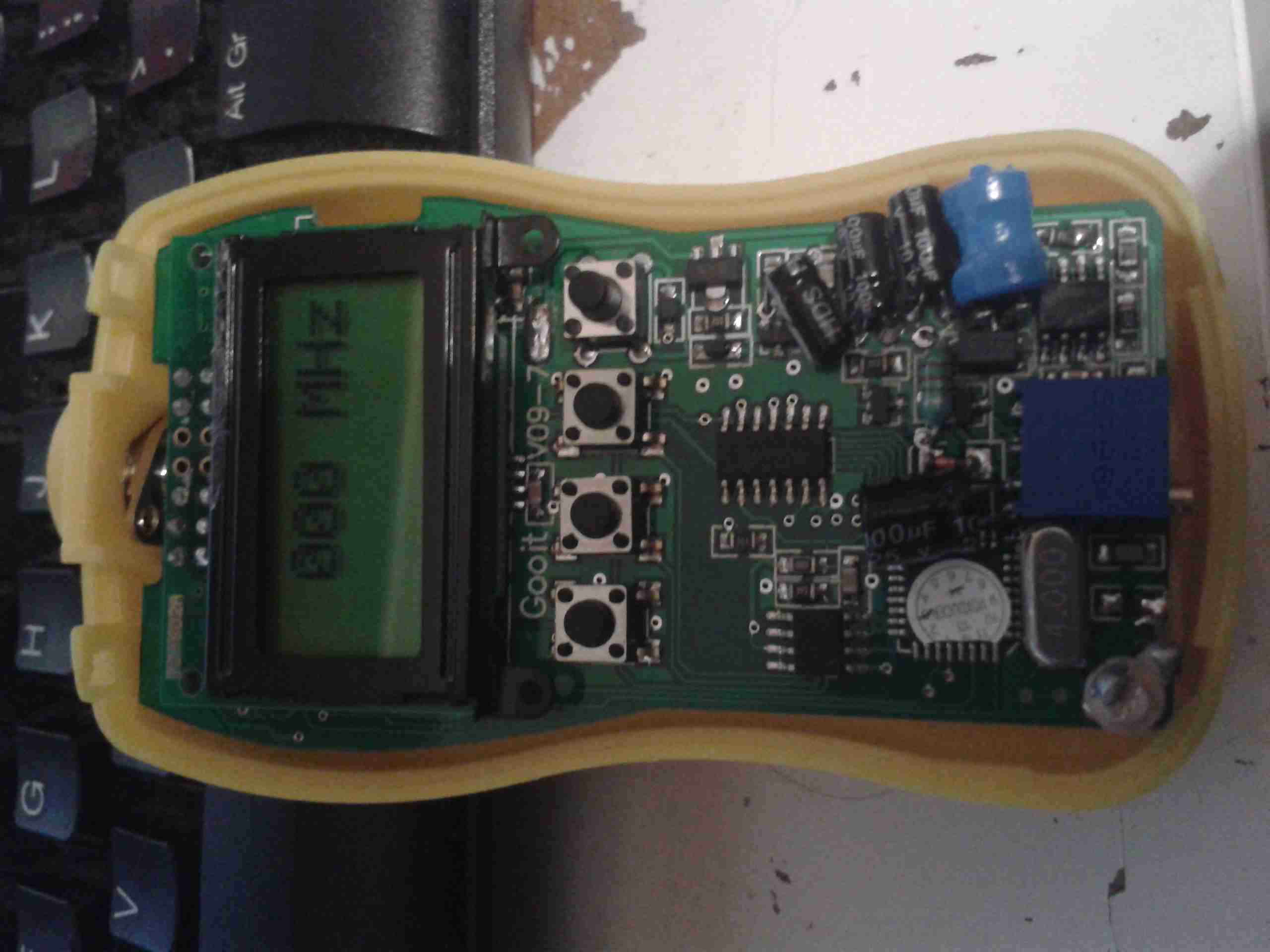
Initial Screen
On removing the front cover, which is just clipped on, there are 4 buttons. The only button that is usually available is the one on the far right, the power button.
I will term these buttons A, B, C, D, starting from the left side.
To get into the initial calibration screen, in the above image, hold button A while the power button (D) is pressed. Release the power button (D), then release button A.
The meter will show the screen above, where the frequency to calibrate can be chosen. This goes in 5MHz steps, 0-500MHz, using the B button to go down in frequency, and the C button to go up.
Once you’ve selected the frequency you wish to calibrate against, press button A, and the following screen will appear:
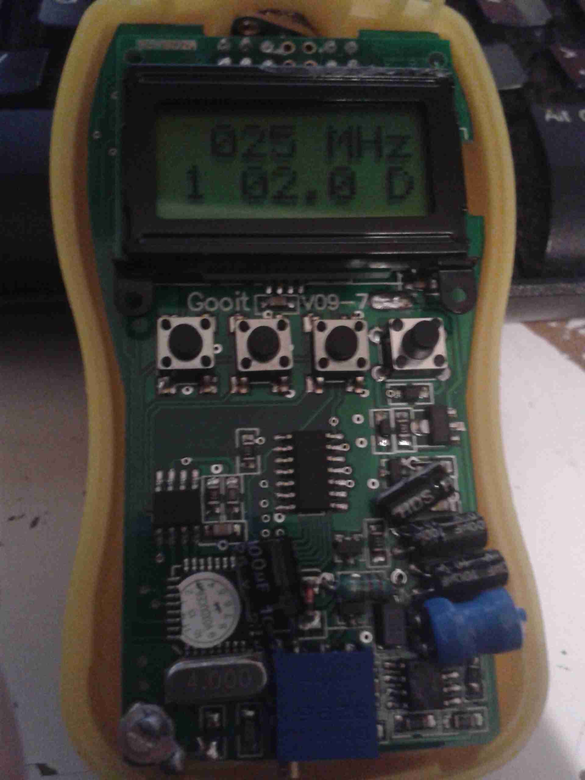
Frequency Calibration Screen
On this screen, the actual calibration can be done.
The number in the bottom left signifies the power level setting, from 1-5. The centre number is the calibration setting in Watts. The D in the bottom corner signifies that the setting is at the factory default.
Button C will cycle through the power level settings, for 2W, 5W, 10W 20W, 40W. This allows calibration at different power levels per frequency.
Once you have the frequency to calibrate, and you’ve selected the power level to calibrate at, connect a known RF power source to the input of the unit.
At this point, key the transmitter, and press button A. The display will change to the following:
Calibration Stage 2
When on this screen, you can set the power level of your RF source. Use the A key for +0.1W, the B key for +1W, and the C key for +10W.
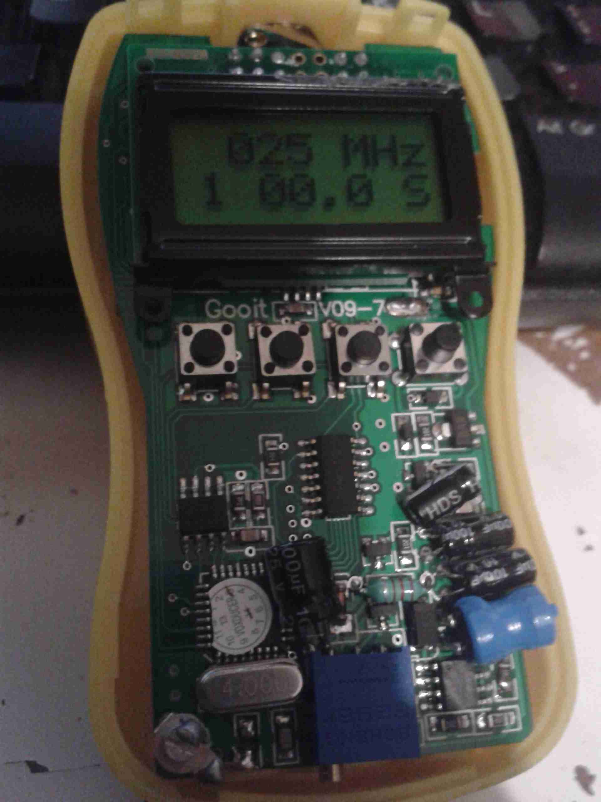
Once you’ve keyed in the power of your source, press button D to save the setting. The “S” in the bottom corner will change to a “C”, to indicate a user calibration has been entered:
Calibration Complete
If you make a mistake with entering the power level, press the “C” key to cycle up to 60W, once at this level, another press of the button will reset the reading to zero. You can then enter the power level again.
If you wish to revert a user-entered setting to the factory default, press button B on the page above. The “D” will reappear in the bottom corner to indicate the setting has been restored.
At this point you can either press button C to calibrate at another power level for this frequency, or press button D to go back to the frequency selection.
Press button D again when at the frequency selection page to turn the unit off. The unit will then power up normally next time the power button (D) is pressed.
One bit of my equipment that I’ve never looked into is my scanner, a handheld Uniden unit. I got this when Maplin Electronics had them on special offer a few years ago.
Uniden Scanner
Here’s the scanner itself, roughly the same size as a usual HT.
Back Cover Removed
Here the back cover has been removed, and the main RF board is visible at the top of the stack. Unfortunately the shielding cans are soldered on this unit, so no looking under there 🙁
On the right hand side of the board next to the antenna input is the main RF filter network, and it’s associated switching. The RF front end is under the shield closest to the front edge.
Controls & 3.3v Regulator
On the other side of the PCB is the Volume & Squelch potentiometers, along with a dedicated 3.3v switching supply. An NJM2360A High Precision DC/DC converter IC controls this one. A 3.3v test point is visible next to the regulator.
RF Board Reverse
Here’s the backside of the RF board, some more interesting parts here. There’s a pair of NJM3404A Single Supply Dual Op-Amp ICs, and a TK10931V Dual AM/FM IF Discriminator IC. This is the one that does all the back-end radio functionality. The audio amplifier for the internal speaker & external headphone jack is also on this PCB, top left. A board-to-board interconnect links this radio board with the main control board underneath.
Control PCB Front
Here’s the front of the control PCB, nothing much to see here, just the LCD & membrane keypad contacts.
Control PCB Reverse
And here’s the reverse side of the control board. All the interesting bits are here. The main microcontroller is on the right, a Renesas M38D59GF, a fairly powerful MCU, with onboard LCD drive, A/D converter, serial interface, 60K of ROM & 2K of RAM. It’s 6.143MHz clock crystal is just below it.
The mating connector for the RF board is in the centre here.
There is also a Microchip 24LC168 16KB I²C EEPROM next to the main microcontroller. This is probably for storing user settings, frequencies, etc.
EEPROM
The rest of this board is dedicated to battery charging and power supply, in the centre is a dual switching controller, I can’t figure out the numbers on the tiny SOT23 components in here, but this is dealing with the DC 6v input & to the left of that is the circuitry for charging the NiMH cells included with the scanner.
PSU
The last bit of this PCB is a BU2092FV Serial In / Parallel Out 4 channel driver. Not sure what this one is doing, it might be doing some signal multiplexing for the RF board interface. Unfortunately the tracks from this IC are routed on the inner layers of the board so they can’t be traced out.
Onboard the boat we have a small issue with a weak TV signal, and this coupled with a 60′ long run of coax is an issue. Due to the loss in the coax, we’ve lost most of the already weak signal.
To try & solve this issue, I’m fitting a masthead amplifier unit.
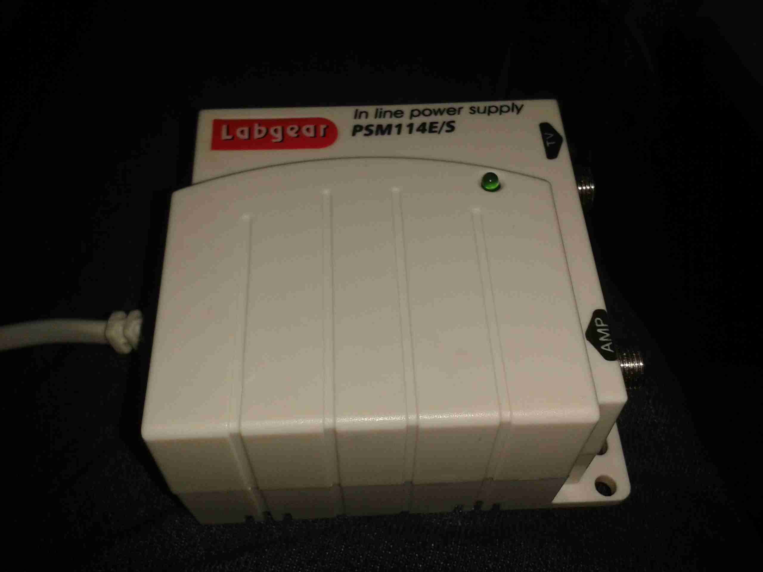
These amplifiers are fed power down the same coax that’s carrying the RF signal, and a special power supply is supplied with the amplifier for this. However it’s only 240v AC, no 12v version available.
Here’s the power supply unit, which fits into the coax between the TV & the antenna.
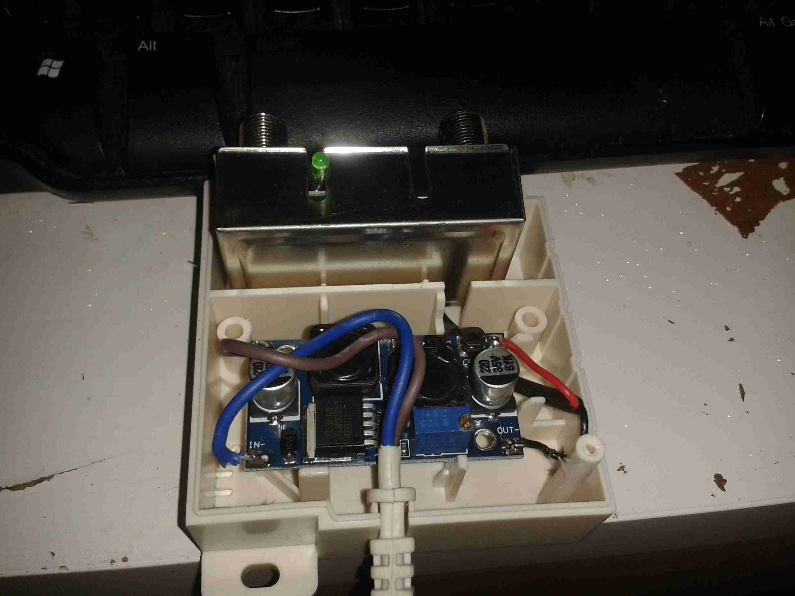
Amplifier Supply
Luckily the 240v supply is easily removable & here has been replaced with a 12v regulator.
New Supply
There’s not very much inside the shielding can, just a few filter capacitors & an RF choke on the DC feed, to keep the RF out of the power supply system.
The original cable is used, so the supply doesn’t even look like it’s been modified from the outside.
More to come on this when I get the amplifier installed along with the new coax run 🙂
The latest addition to my radio shack is the GY561 frequency & power meter, which has already come in useful for measuring the output power of all my radios.
GY561
It’s a small device, roughly the same size & weight as a stock UV-5R. Power is provided by 3 AAA cells.
Display
The display is a standard HD44780 8×2 module. The display on this unit isn’t backlit, so no operating in the dark.
Cover Removed
The cover pops off easily to allow access to the internals, without having to remove any screws!
The 4 screws on the back of the unit hold the heatsink plate for the 50W 50Ω dummy load resistor.
Removing the cover reveals a couple of adjustments, for frequency & RF power calibration.
There are also 3 tactile switches that aren’t on the front panel. According to the manual (which in itself is a masterpiece of Chinglish), they are used to software calibrate the unit if an accurate RF power source is available. I will attempt to do a reasonable translation when time allows.
Disassembly further than this involves some desoldering in awkward places, so a search of the internet revealed an image of the rest of the internal components. In the case of my meter, all the part numbers have been scrubbed off the ICs in an attempt to hide their purpose. While it’s possible to cross-reference IC databooks & find the part numbers manually, this process is a time consuming one. Luckily the image I managed to locate doesn’t have the numbers scrubbed.
Total Disassembly
Under the LCD is some 74HC series logic, and a prescaler IC as seen in the previous frequency counter post. However in this unit the prescaler is a MB506 microwave band version to handle the higher frequencies specified.
In this case however the main microcontroller is an ATMEGA8L.
This is complemented by a SN54HC393 4-bit binary counter for the frequency side of things. This seems to make it much more usable down to lower frequencies, although the manual is very generous in this regard, stating that it’s capable of reading down to 1kHz. In practice I’ve found the lowest it reliably reads the frequency input is 10MHz, using my AD9850 DDS VFO Module as a signal source.
It did however read slightly high on all readings with the DDS, but this could have been due to the low power output of the frequency source.
Just like the other frequency counter module, this also uses a trimmer capacitor to adjust the microcontroller’s clock frequency to adjust the calibration.
The power supply circuitry is in the bottom left corner of the board, in this case a small switching supply. The switching regulator is needed to boost the +4.5v of the batteries to +5v for the logic.
Also, as the batteries discharge & their terminal voltage drops, the switching regulator will allow the circuit to carry on functioning. At present I am unsure of the lower battery voltage limit on the meter, but AAA cells are usually considered dead at 0.8v terminal voltage. (2.4v total for the 3 cells).
When turned on this meter draws 52mA from the battery, and assuming 1200mAh capacity for a decent brand-name AAA cell, this should give a battery life of 23 hours continuous use.
On the back of the main PCB is a 5v relay, which seems to be switching an input attenuator for higher power levels, although I only managed to trigger it on the 2m band.
Finally, right at the back attached to an aluminium plate, is the 50Ω dummy load resistor. This component will make up most of the cost of building these, at roughly £15.
On my DVM, this termination reads at about 46Ω, because of the other components on the board are skewing the reading. There are a pair of SMT resistors, at 200Ω & 390Ω in series, and these are connected across the 50Ω RF resistor, giving a total resistance of 46.094Ω.
This isn’t ideal, and the impedance mismatch will probably affect the calibration of the unit somewhat.
The heatsinking provided by the aluminium plate is minimal, and the unit gets noticeably warm within a couple of minutes measuring higher power levels.
High power readings should definitely be limited to very short periods, to prevent overheating.
The RF is sampled from the dummy load with a short piece of Teflon coax.
There’s a rubber duck antenna included, but this is pretty useless unless it’s almost in contact with the transmitting antenna, as there’s no input amplification. It might be handy for detecting RF emissions from power supplies, etc.
For the total cost involved I’m not expecting miracles as far as accuracy is concerned, (the manual states +/-10% on power readings).
The frequency readout does seem to be pretty much spot on though, and the ability to calibrate against a known source is handy if I need some more accuracy in the future.
I’ve also done an SWR test on the dummy load, and the results aren’t good.
At 145.500 MHz, the SWR is 3:1, while at 433.500 it’s closer to 4:1. This is probably due to the lower than 50Ω I measured at the meter’s connector.
These SWR readings also wander around somewhat as the load resistor warms up under power.
I’ll probably also replace the AAA cells with a LiPo cell & associated charge/protection circuitry, to make the unit chargeable via USB. Avoiding disposable batteries is the goal.
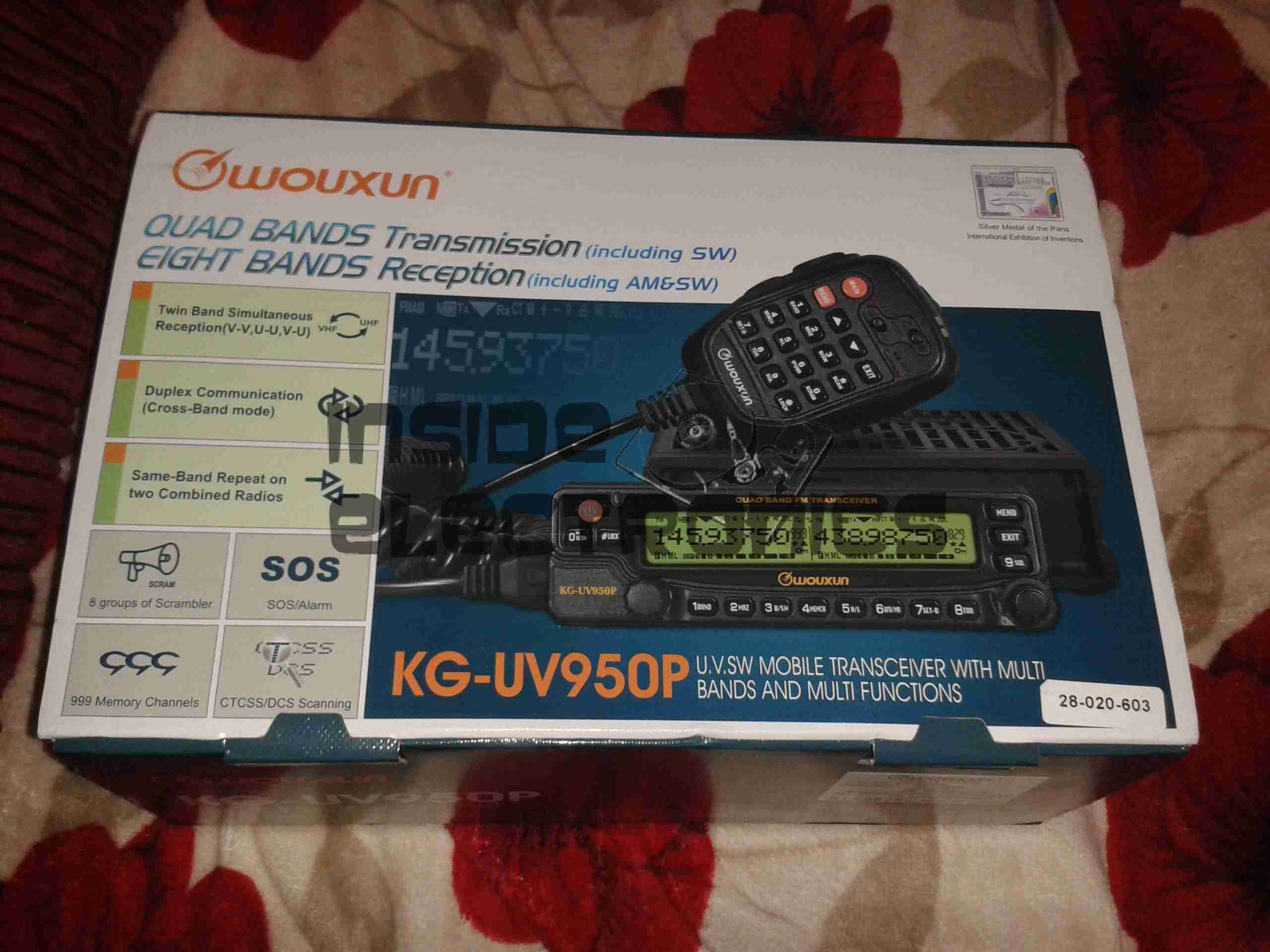
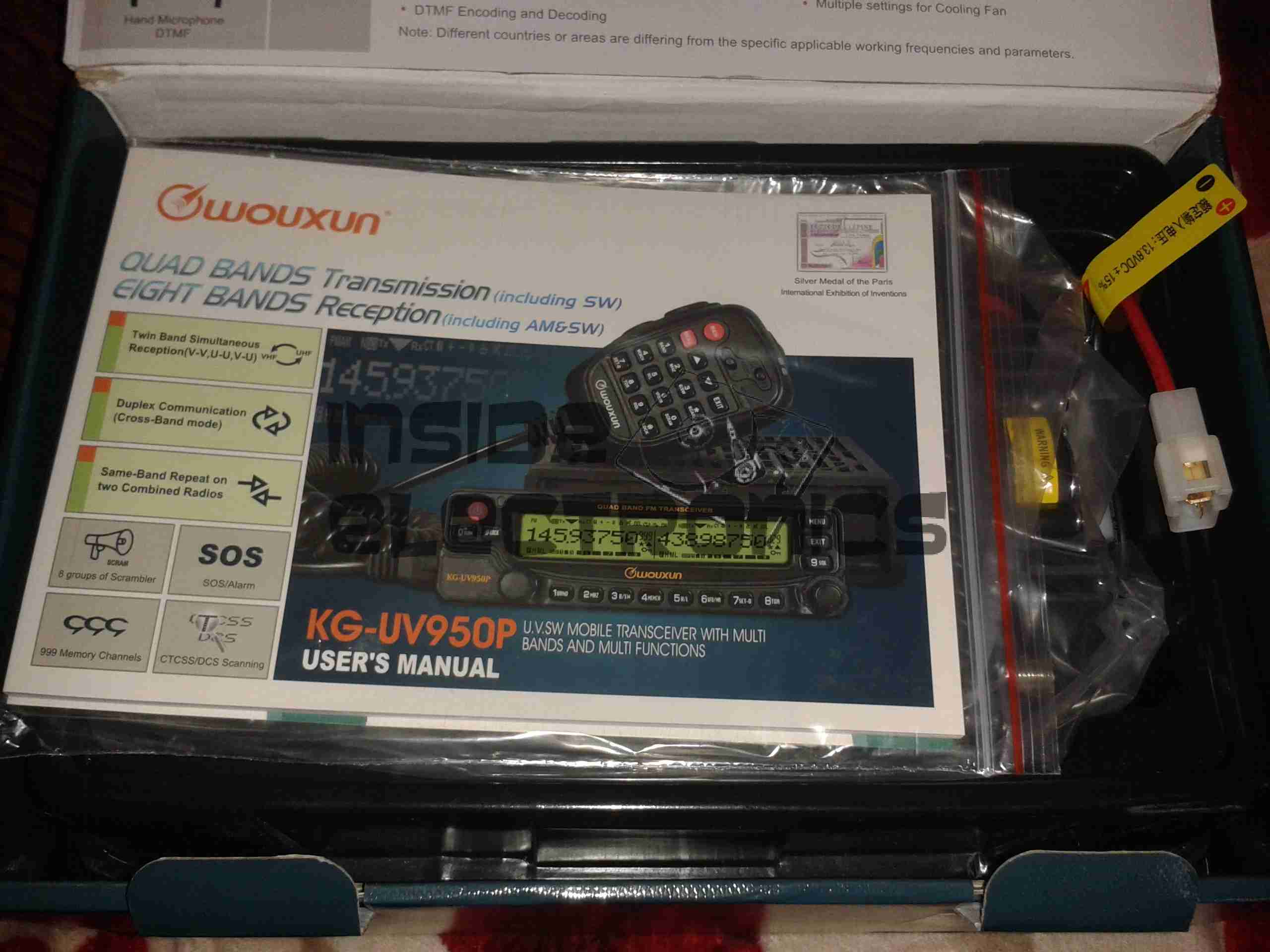
After running on handies for all of my Ameteur Radio life, I figured it was time for a new radio, this time a base station/mobile rig, & after some looking around I decided on the Wouxun KG-UV950P.
Shown below is the radio as delivered:
Wouxun Boxed
This radio has the capability to transmit quad-band, on 6m, 10m, 2m & 70cm. It also has the capability to receive on no fewer than eight bands. Also included in the feature set is airband receive, & broadcast FM receive.
TX power is up to 50W on 2m, 40W on 70cm, & 10W on 6m/10m.
Opened
For once with a Chinese piece of electronic equipment, the manual is very well printed, and in very good English.
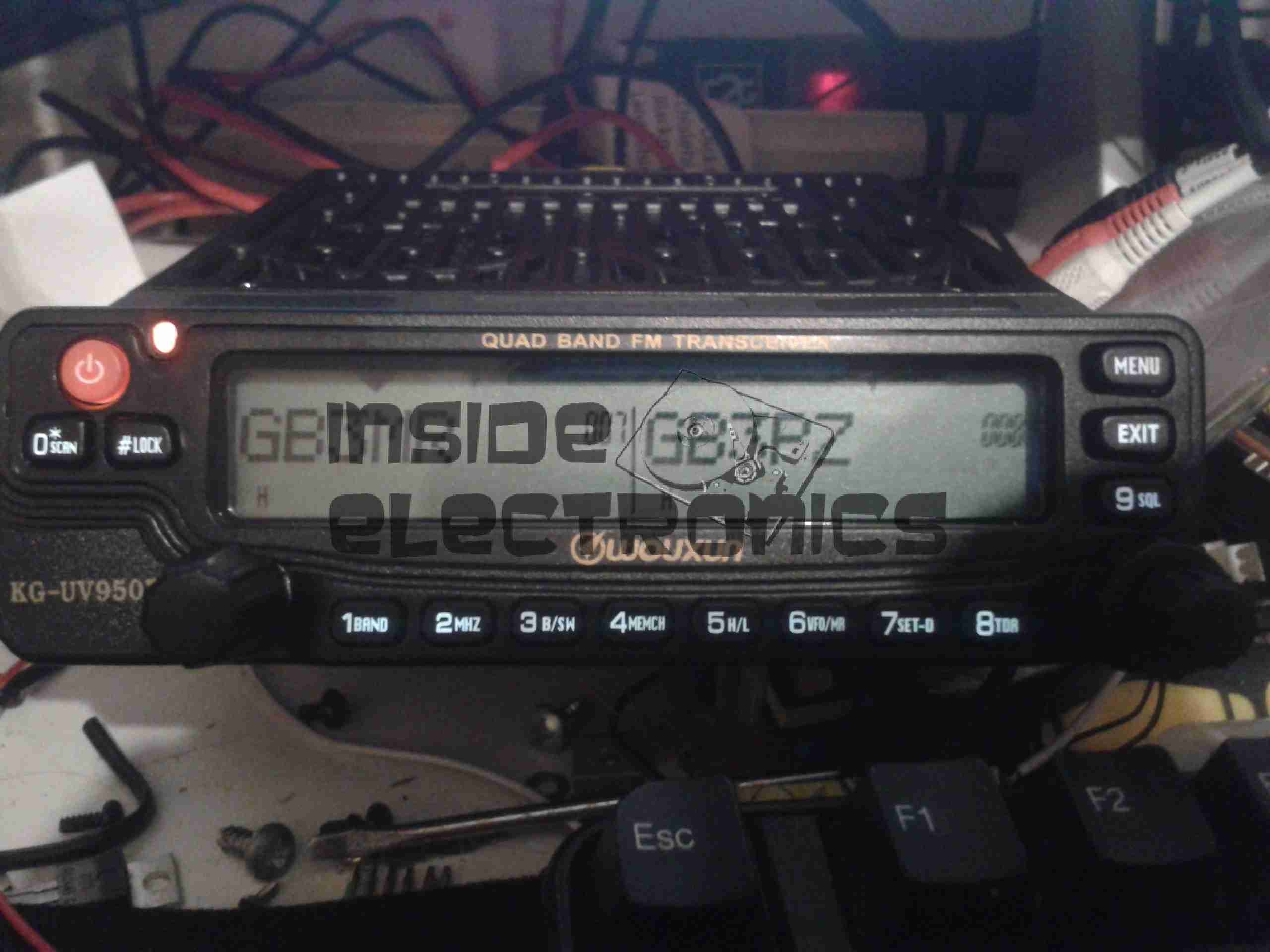
Radio Operating
Here is the radio in operation, connected to my 65A 12v power supply. I have the radio set here monitoring a couple of the local 70cm repeaters.
The display is nice & large – easy to see at a glance which station you’re tuned to. The backlight is also software settable to different colours.
Status indicators on the top edge of the display can be a bit difficult to see unless the panel is directly facing the user though, not to mention that they are rather small.
This radio is true dual-watch, in that both VFOs can be receiving at the same time, this is effected by a pair of speakers on the top panel:
Speakers
The left VFO speaker is smaller than the right, so the sound levels differ slightly, but overall sound quality is excellent. There is also provision on the back of the unit to connect external speakers.
The dual volume controls on the right hand bottom corner of the control panel are fairly decent, if a little twitchy at times. There is also a fair amount of distortion on the audio at the higher volume levels.
The controls themselves are potentiometers, but the controller appears to read the setpoint with an ADC – this means that if the control is set to just the right point, the selected level will jump around on the display & never settle down.
The radio itself is built from a solid aluminium casting, mostly for heatsinking of the main RF output stage MOSFETs. This gives the radio a very rugged construction.
A small fan is provided on the rear for cooling when required. This can be set in software to either be constantly running, (it’s pretty much silent, so this is advantageous), or only run when in TX mode. The fan will also automatically come on when a high internal temperature is detected.
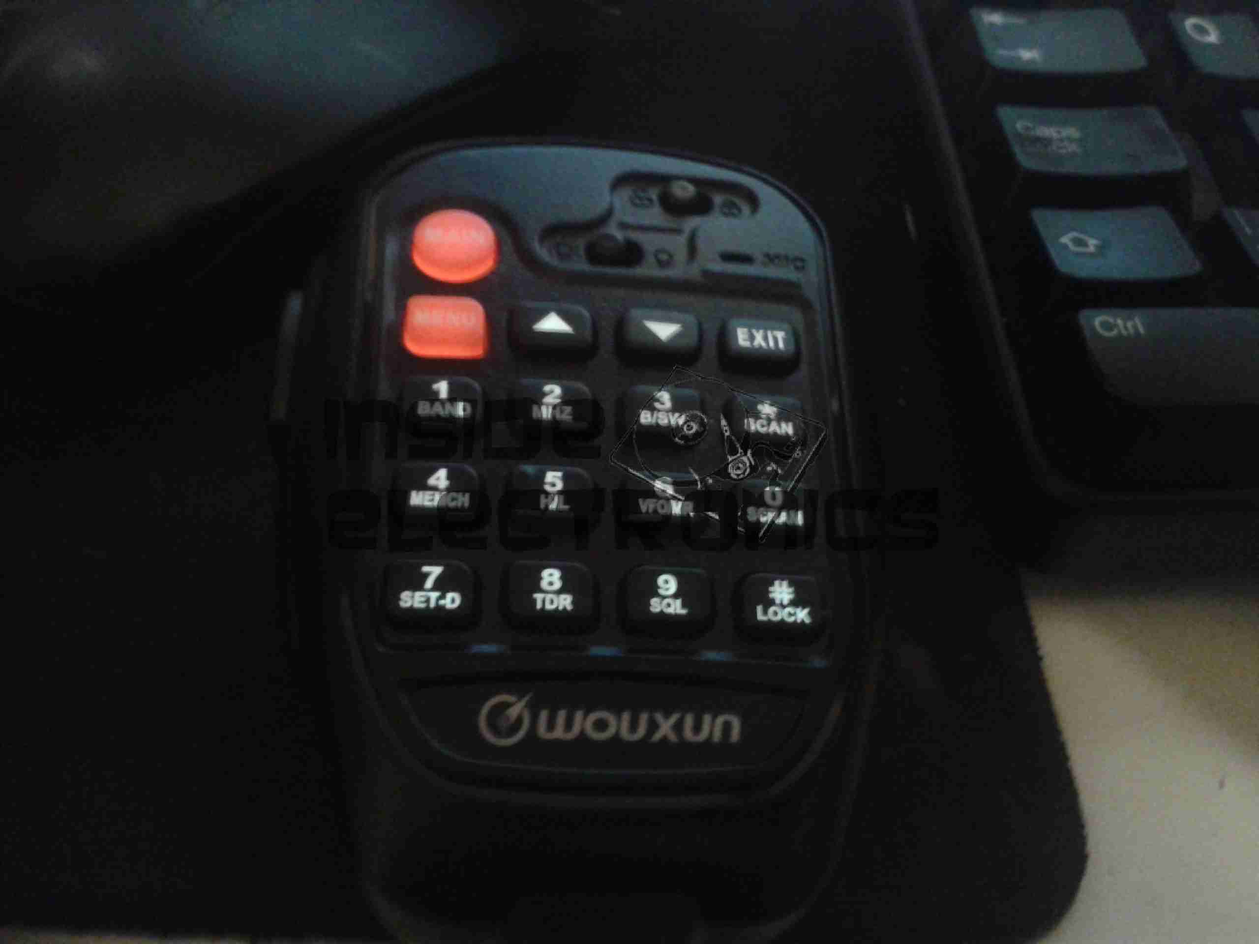
Hand Mic
Here is the microphone. Like the main unit of the radio this is also very solidly built, fits nicely in the hand & the PTT has a nice easy action, which helps to prevent straining hands while keeping the TX keyed.
Conveniently, all of the controls required to operate the radio are duplicated on this mic, along with a control lock switch, & backlighting for the buttons.
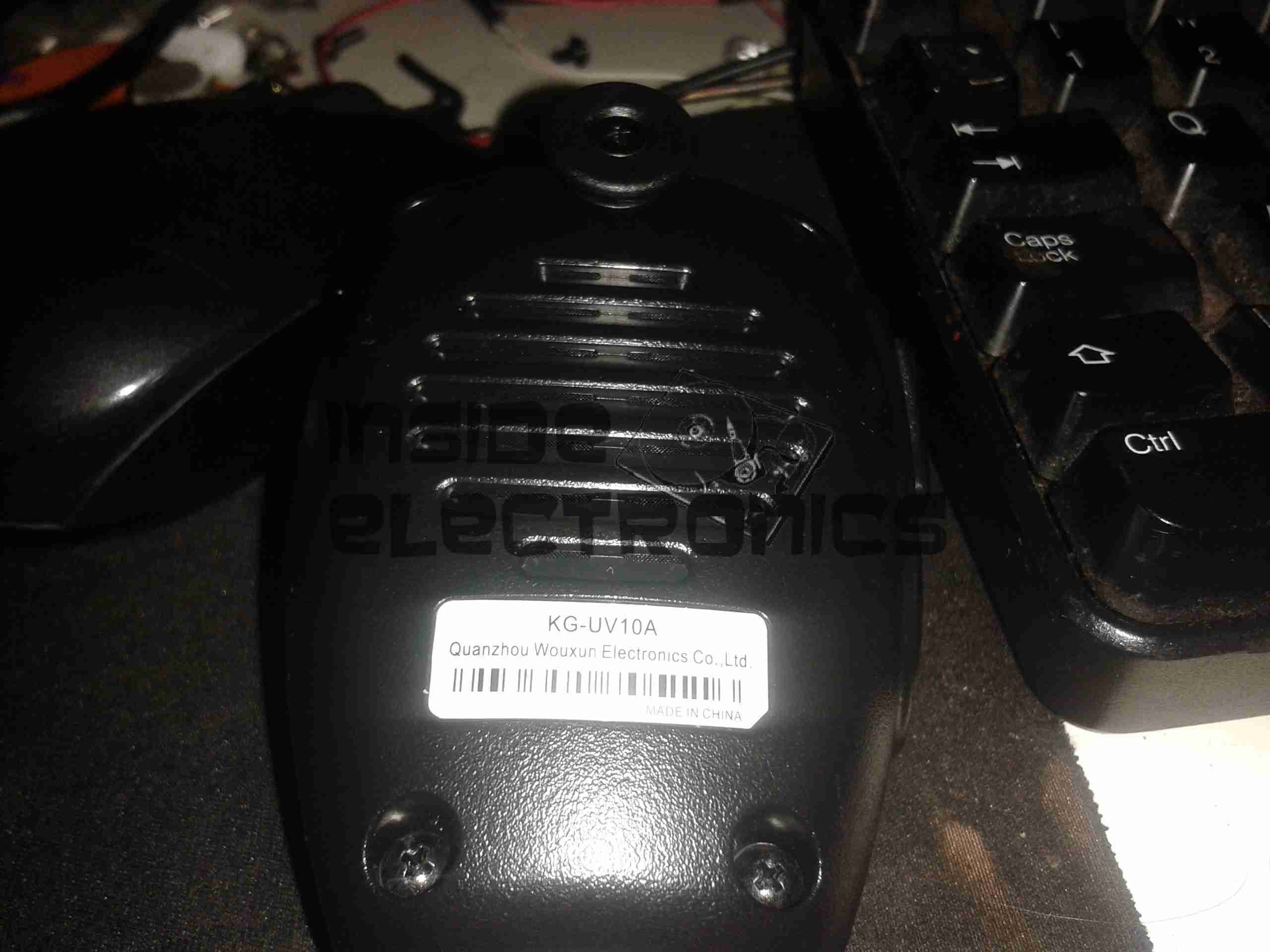
Another Speaker
Another output speaker is placed in the back of the mic. This one can be activated through the menu system, to either use the main body speakers, the mic mounted one, or both.
A mounting hook for the mic is provided to attach to any convenient surface.
Radio Back
Here’s the back of the radio, with some of the big heatsink fins, the fan in the centre. To the left is the PL259 RF output, this looks to be a high quality Teflon insulated one. On the right are the power input leads & the external speaker outputs.
External Speaker Sockets
The external speaker connections are via 3.5mm jacks. I haven’t yet tested this feature.
Remote Mounting Plate
The control panel of this radio is detachable from the main body, and a pair of adaptors are provided. This either allows the radio display to be angled upwards toward the user, set parallel, or even mounted remotely. A control extension cable is provided to allow the main body to be mounted a fair distance away.
External Interface Connectors
On the left of the radio is the PC control & programming port, & the mic connector. Wouxun *really* like RJ-45 connectors, they’ve used them for everything on this radio.
Also visible here is the tilted faceplate adaptor.
The supplied software to program the radio, while functional, is absolutely horrific. Hopefully someone will add support for this radio into CHIRP. Anything would be an improvement in this area.
Everything considered, I like this radio. It’s very solidly built, easy to use, and sounds brilliant.
TX audio is great, (or so my other contacts tell me).
Unsurprisingly, the unit gets warm while transmitting, however on high power, it does get uncomfortably warm, and the built in fan does little in the way of helping when a long QSO is in progress. I may remedy this at some stage with a more powerful fan. A little more airflow would do wonders.
If the programming software was built as well as the radio, I’d have zero serious complaints.
At full power, the radio pulls ~10A from the power supply, at 12.9v DC.
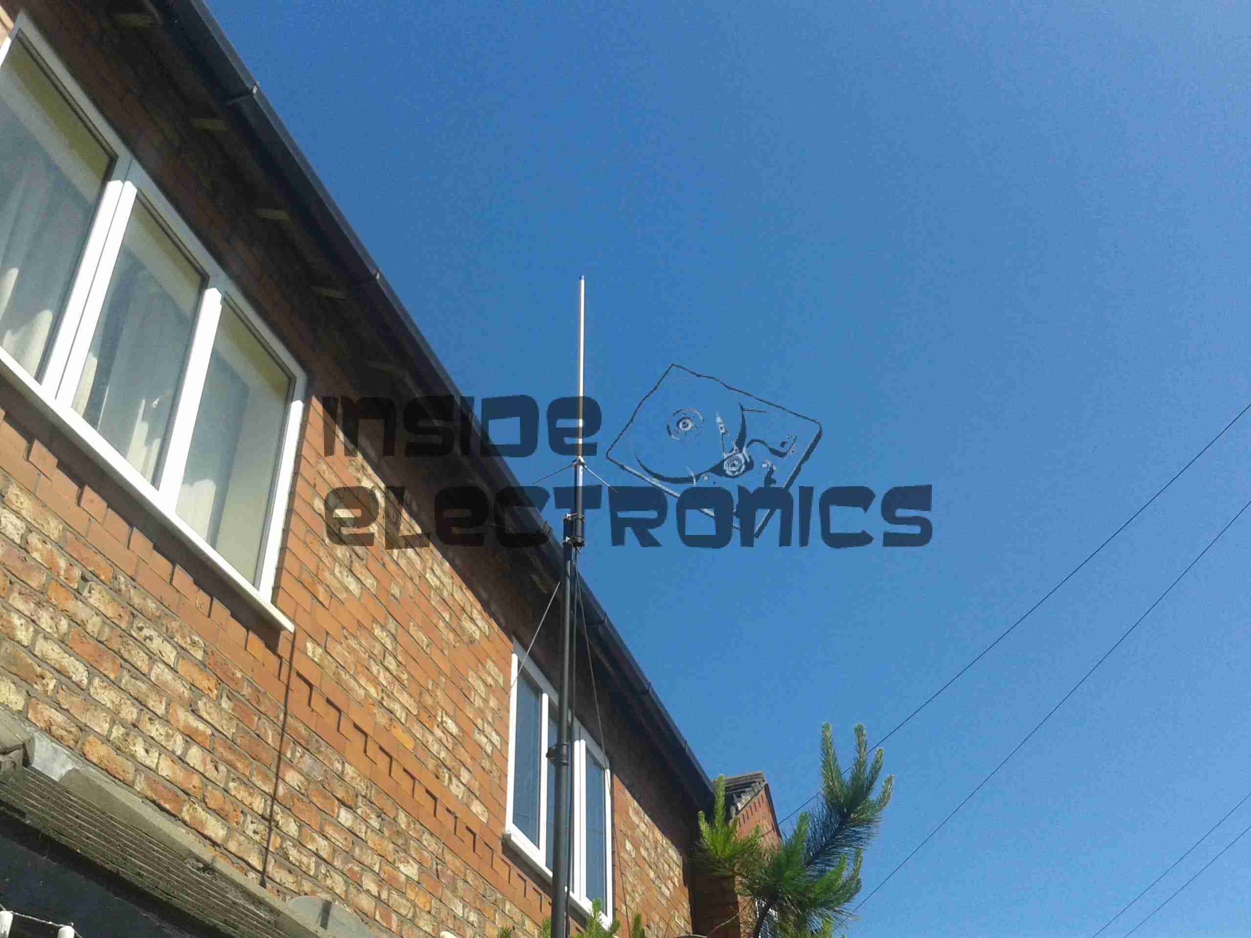
As for the antenna I’m currently using, it’s a Diamond X30, mounted on a modified PA speaker stand, at ~30 feet above ground. The feeder is high quality RG-213.
TX Antenna
When I manage to get the set disconnected, a partial teardown will be posted, with some intimate details about the internals. Stay tuned!
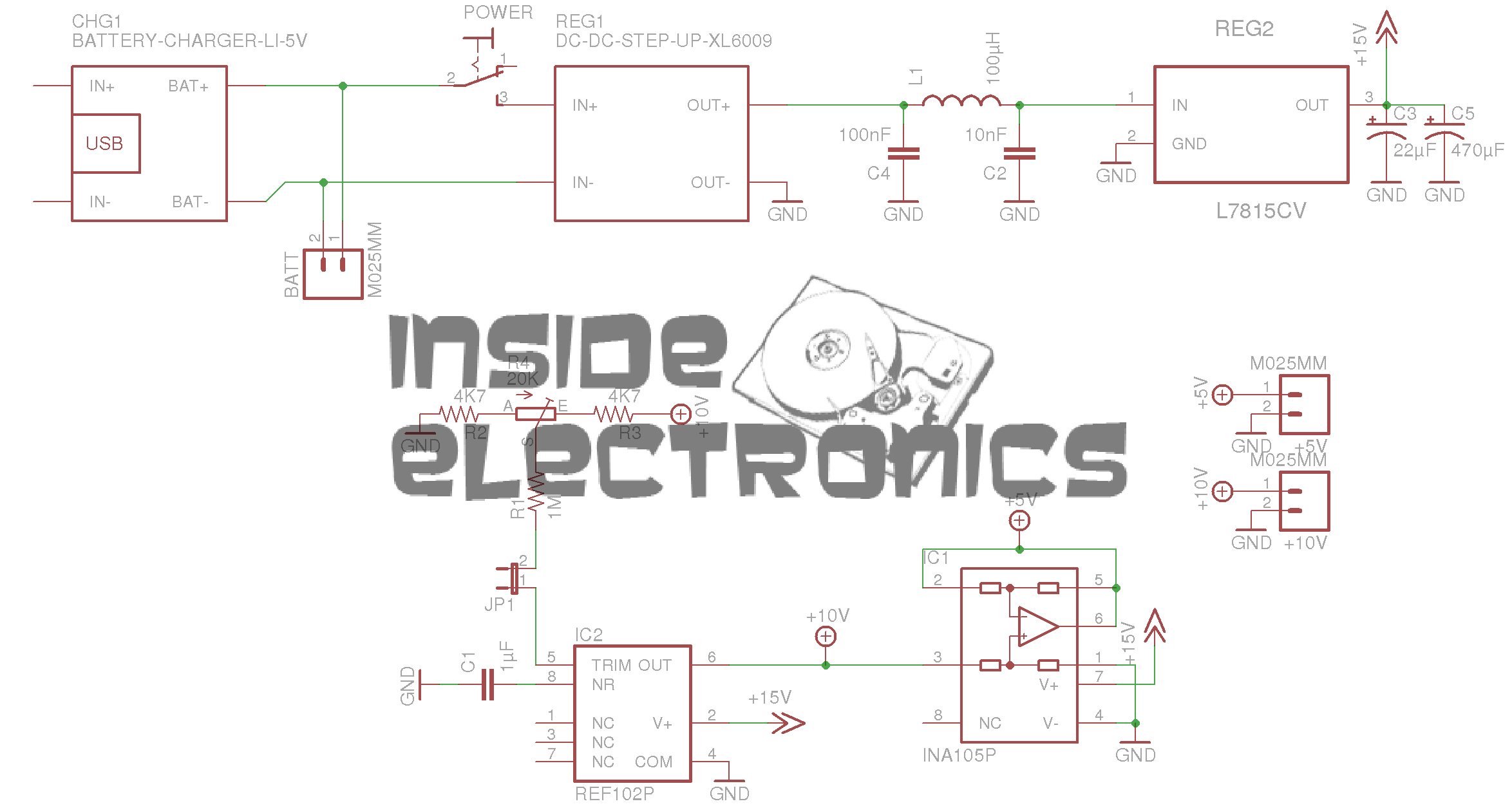
After watching a video over at Scullcom Hobby Electronics on YouTube, I figured I’d build one of these precision references to calibrate my multimeters.
It’s based around a REF102P 10v precision reference & an INA105P precision unity gain differential amplifier.
For full information, check out the video, I won’t go into the details here, just my particular circuit & PCB layout.
In the video, Veroboard is used. I’m not too fond of the stuff personally. I find it far too easy to make mistakes & it never quite looks good enough. To this end I have spun a board in Eagle, as usual.
Precision Ref SCH – Click to Embiggen
Here’s the schematic layout, the same as is in the video.
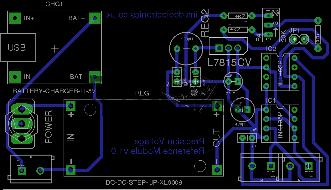
Precision Ref BRD
As usual, the Eagle CAD layout files can be found at the bottom of the post.
And the associated PCB layout. I have added the option to be able to tweak the output, to get a more accurate calibration, which can be added by connecting JP1 on the PCB.
As in the original build, this unit uses pre-built DC-DC converter & Li-Ion charger modules. A handy Eagle library can be found online for these parts.
I have however left off the battery monitor section of the circuit, since I plan to use a protected lithium cell for power. This also allowed me to keep the board size down, & use a single sided layout.
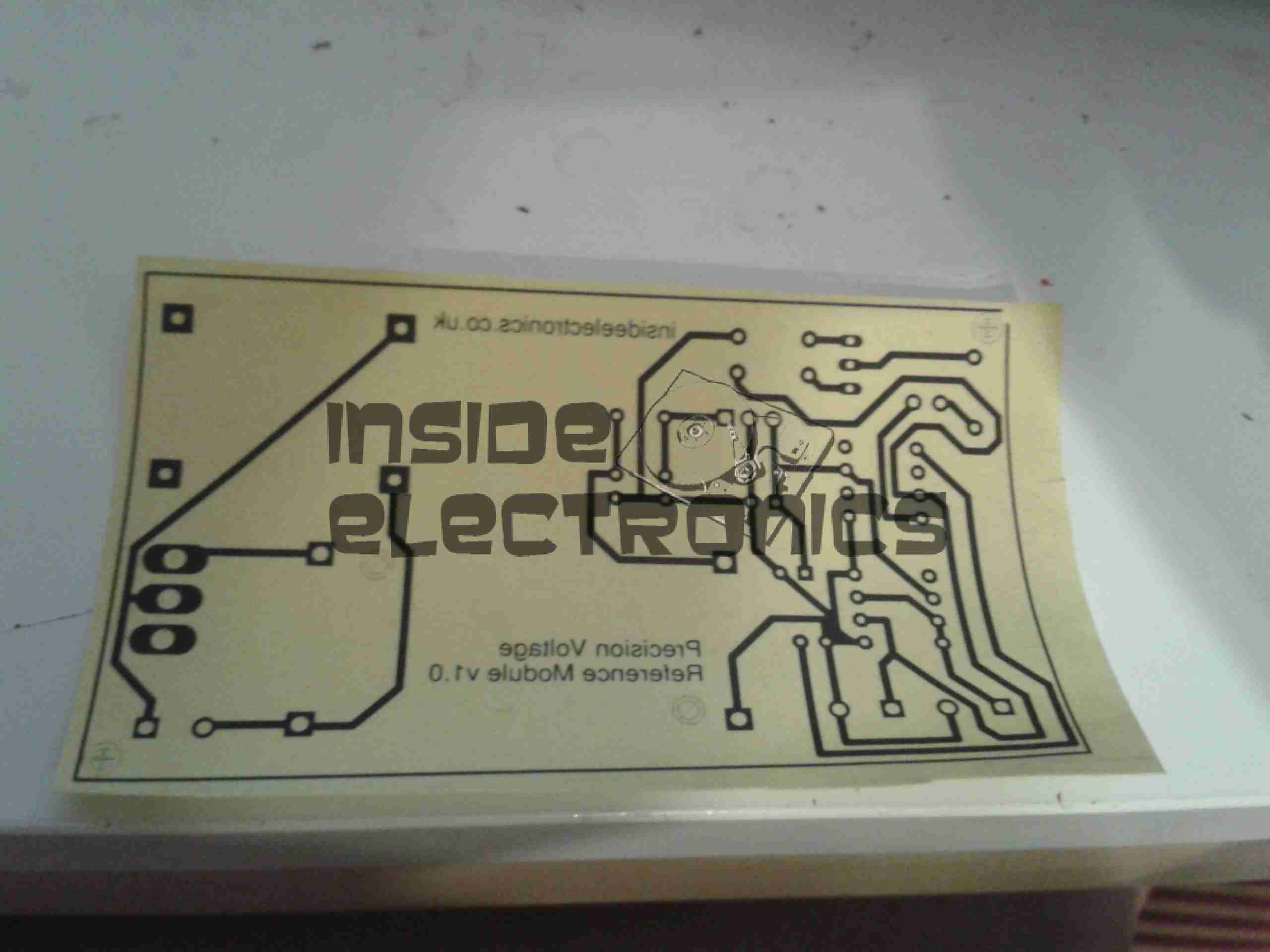
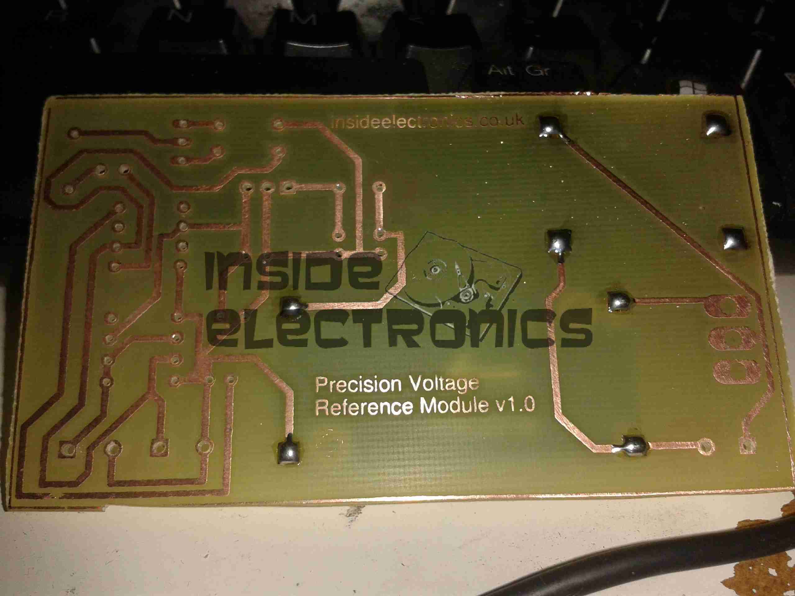
Toner Transfer Paper
Here’s the track layout ready to iron onto the copper clad board. I use the popular toner transfer system with special paper from eBay, this stuff has a coating that allows the toner to easily be transferred to the PCB without having to mess about with soaking in water & scraping paper off.
Ironed On
Here’s the paper having just been ironed onto the copper. After waiting for the board to cool off the paper is peeled off, leaving just the toner on the PCB.
Etched PCB
PCB just out of the etch tank, drilled & with the solder pins for the modules installed. Only one issue with the transfer, in the bottom left corner of the board is visible, a very small section of copper was over etched.
This is easily fixed with a small piece of wire.
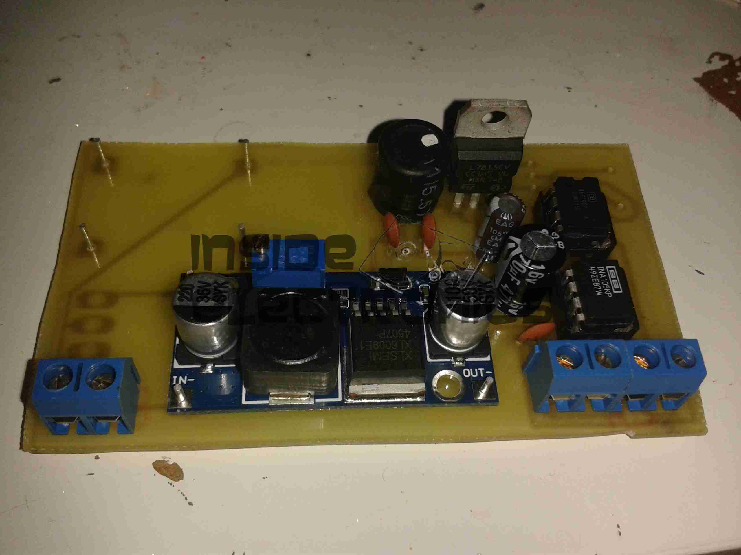
Components Populated
Main components populated. The DC-DC converter is set at 24v output, which the linear regulator then drops down to the +15v rail for the reference IC. The linear section of the regulator, along with the LC filter on the output of the switching regulator produce a low-ripple supply.
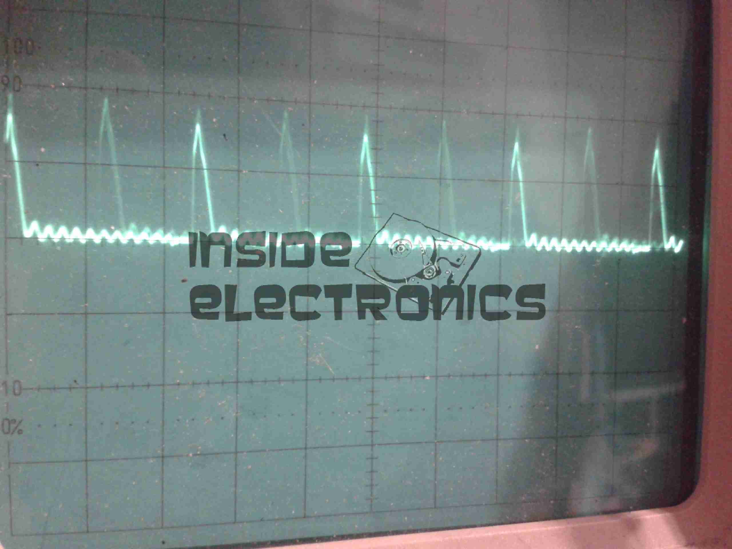
SMPS Ripple
Here’s the scope reading the AC ripple on the output of the DC-DC converter. Scale is 100mV/Div. Roughly 150mV of ripple is riding on top of the DC rail.
Linear PSU Ripple
And here’s the output from the linear regulator, scale of 50mV/Div. Ripple has been reduced to ~15mV for the reference IC.
In total the circuit as built has a power consumption of ~0.5W, most of which is being dissipated as heat in the linear part of the PSU.
Here’s another viewfinder CRT, removed from a 1980’s vintage VHS camera I managed to get cheap from eBay.
This unit is very similar to the last one I posted about, although there are a few small differences in the control circuitry.
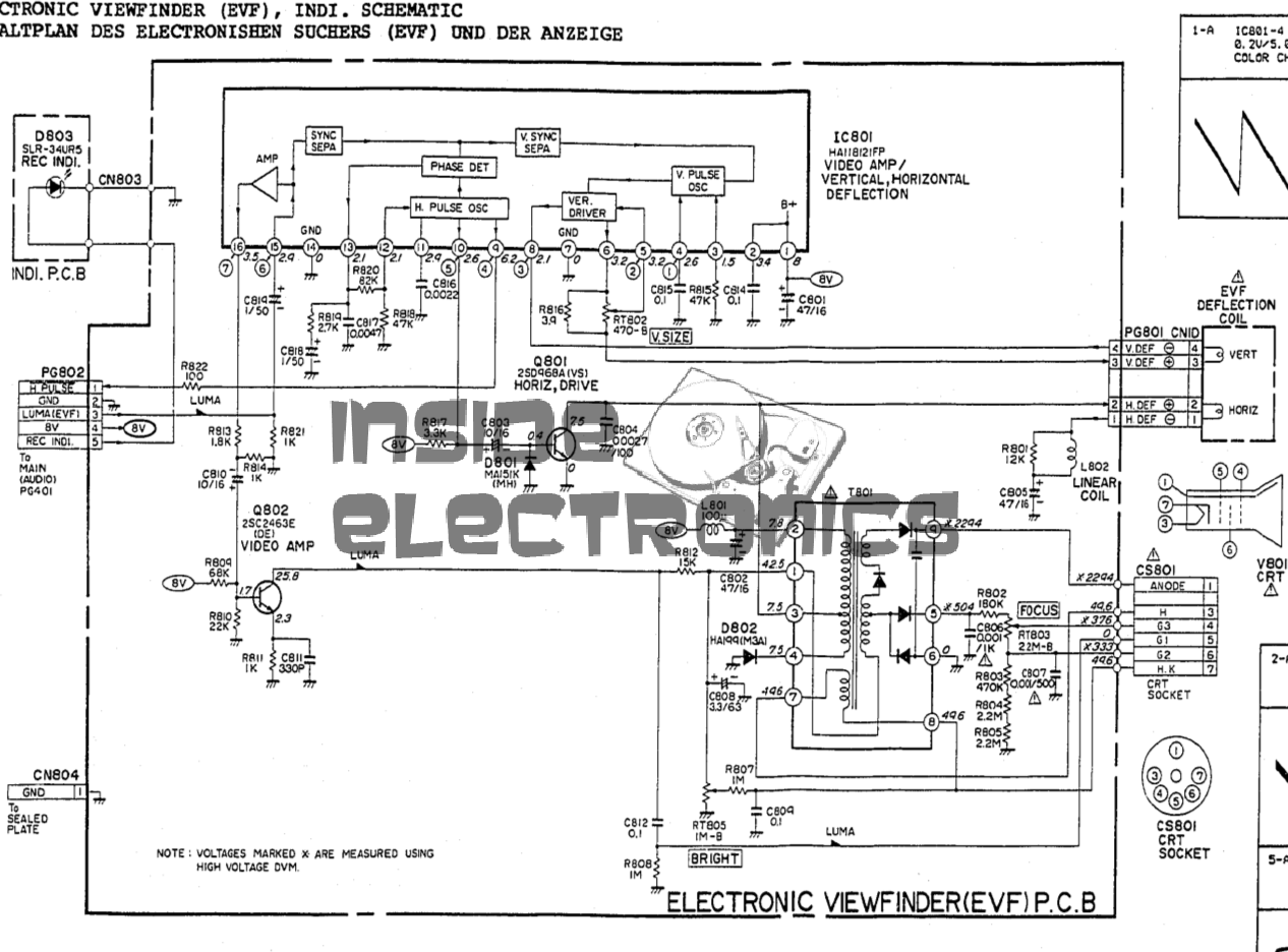
Viewfinder Schematic – Click to Embiggen
Here’s the schematic, showing all the functional blocks of the viewfinder circuitry. An integrated viewfinder IC is used, which generates all the required scan waveforms for the CRT.
On the left is the input connector, with the power & video signals. Only pins 2 (GND), 3 (Composite video), & 4 (+8v) are needed here. Pin 1 outputs a horizontal sync signal for use elsewhere in the camera, while pin 5 fed the recording indicator LED.
To make connection easier, I have rearranged the wires in the input connector to a more understandable colour scheme:
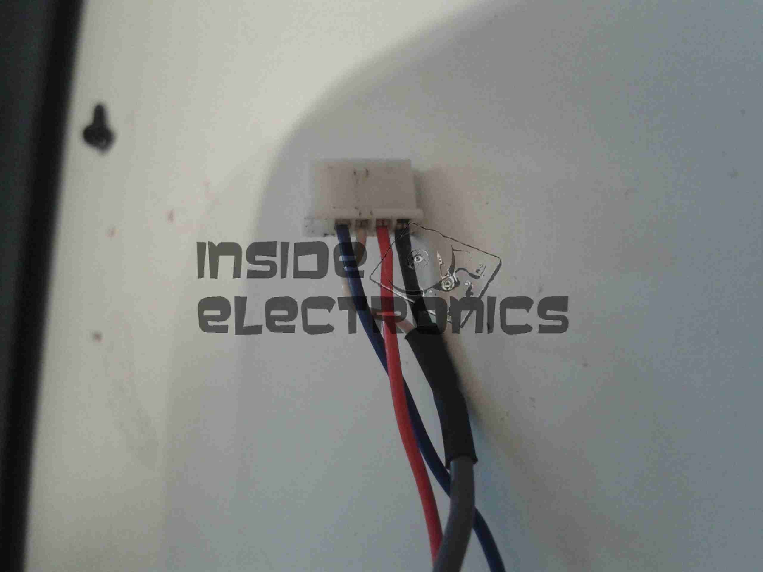
Input Connector
Red & Blue for power input, & a coax for the video. For the video GND connection, I have repurposed the Rec. LED input pin, putting a shorting link across where the LED would go to create a link to signal ground. Keeping this separate from the power GND connection reduces noise on the CRT.
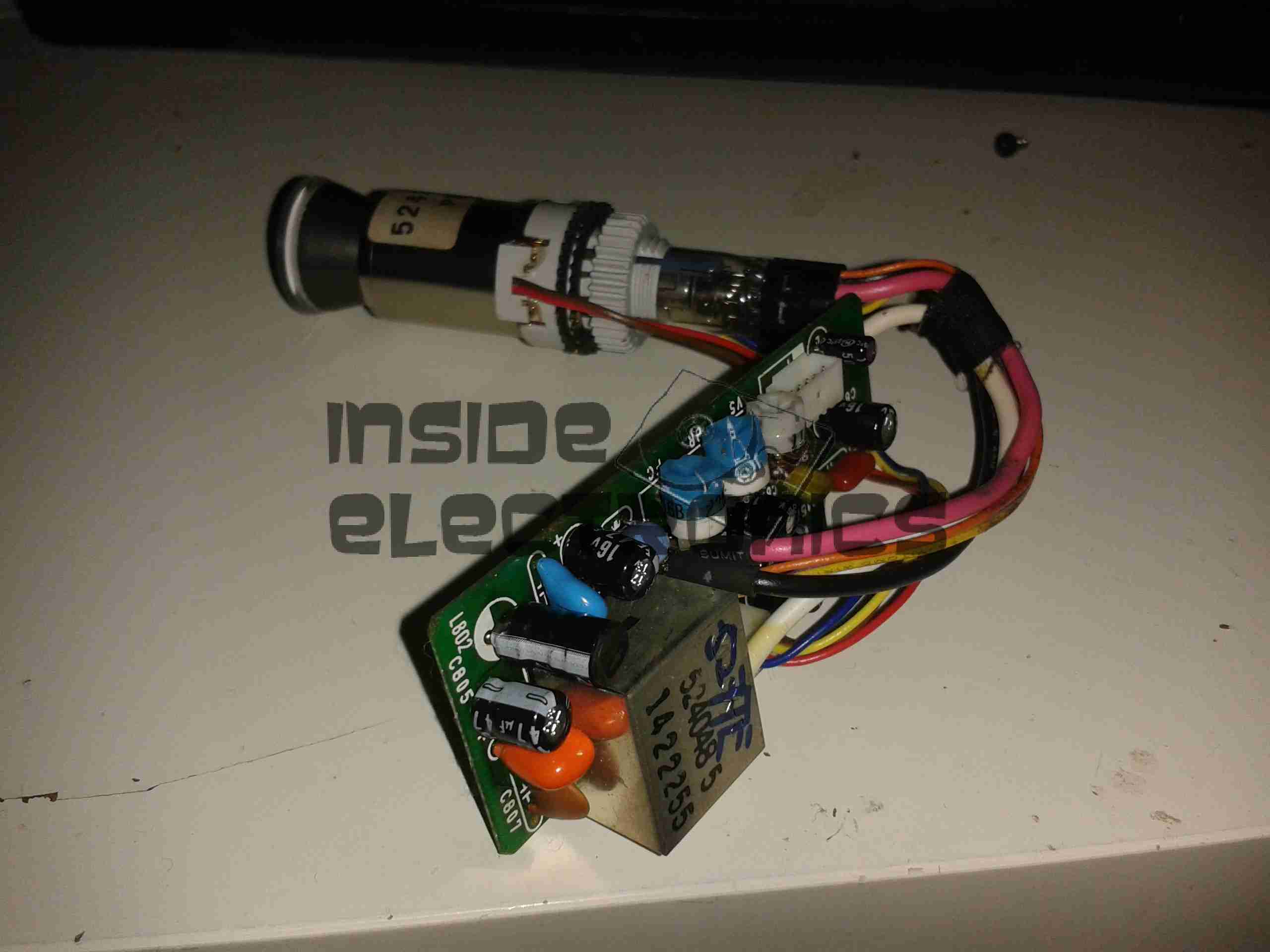
Viewfinder CRT Assembly
Here’s the complete assembly liberated from it’s plastic enclosure.
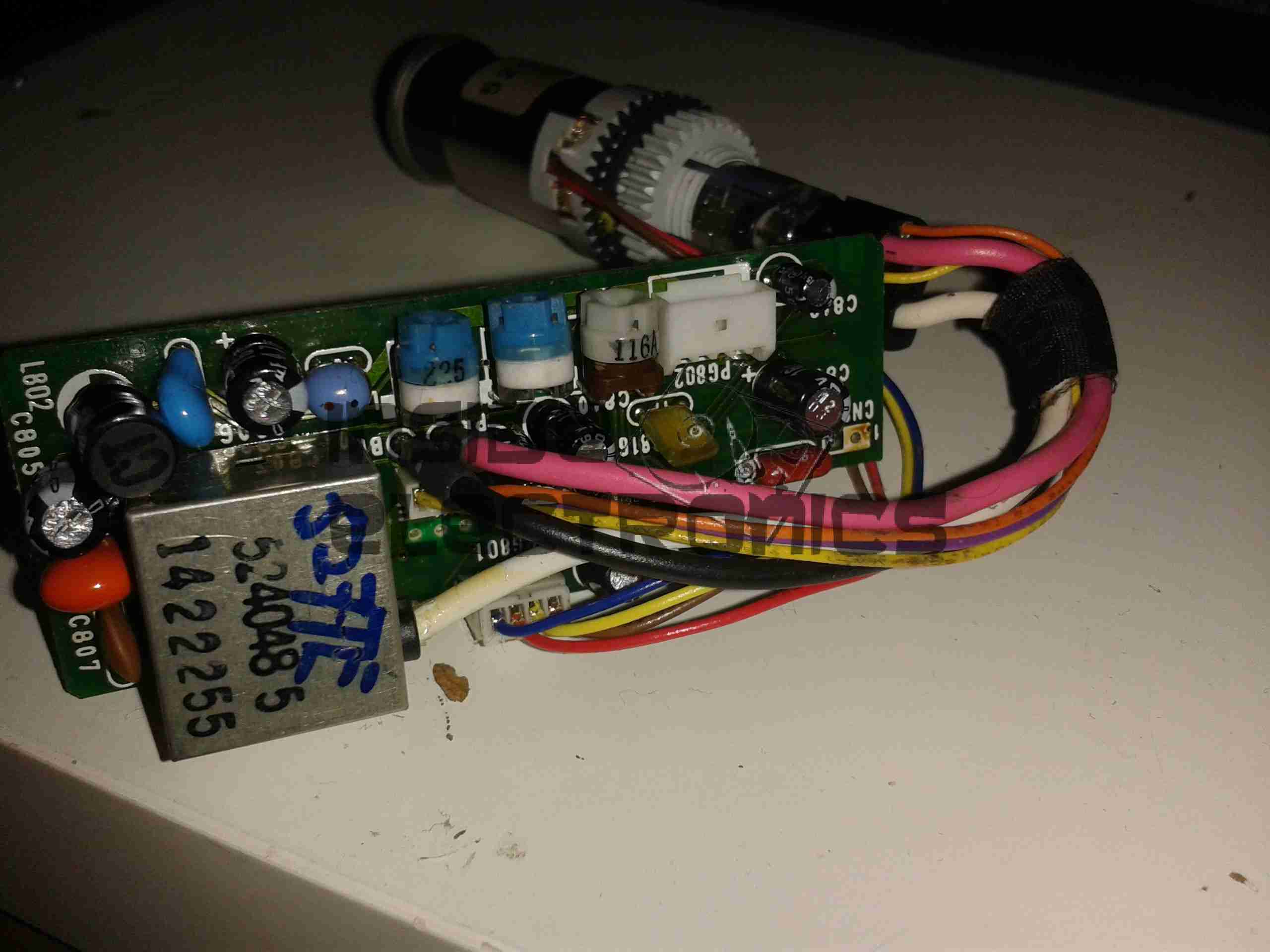
PCB Closeup
Closeup of the control PCB. The 3 potentiometers control the CRT brightness, focus & vertical size.
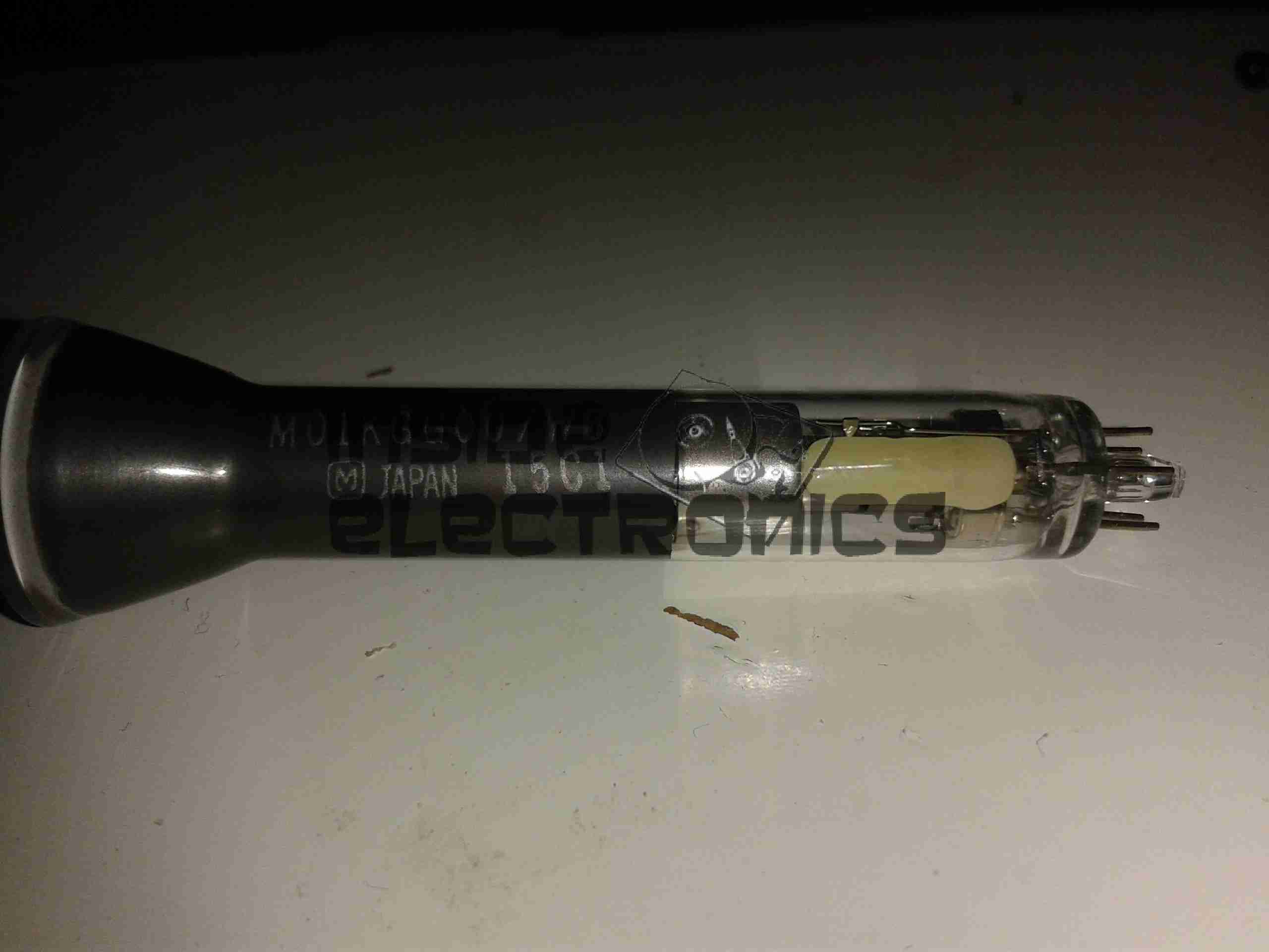
M01KGG007WB CRT
The tiny CRT. Only ~60mm in length, with an 18mm screen size. This tube runs on +2294v final anode voltage. Much higher than I expected.
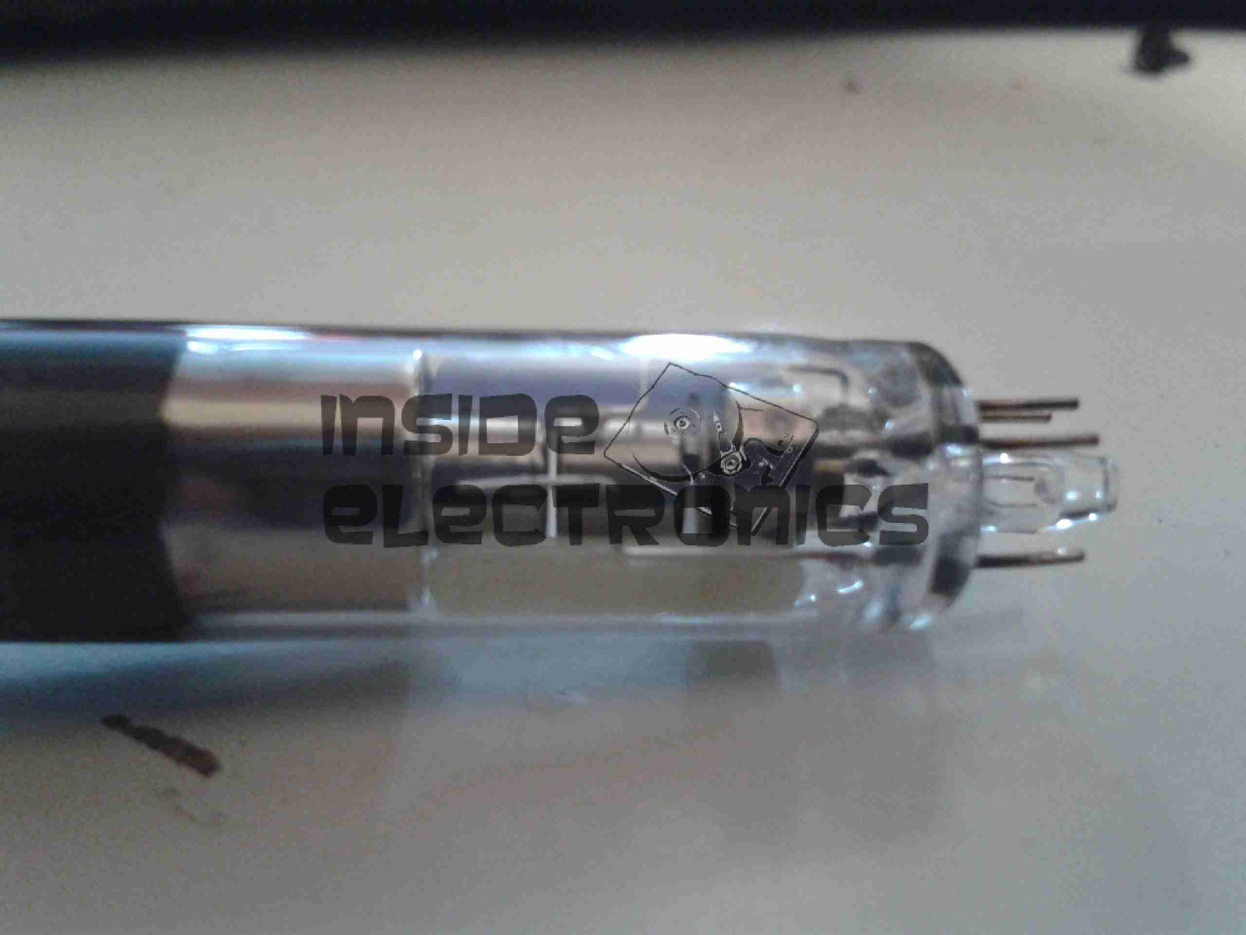
Electron Gun Closeup
The electron gun assembly, with the cathode, focus & final anode cups.
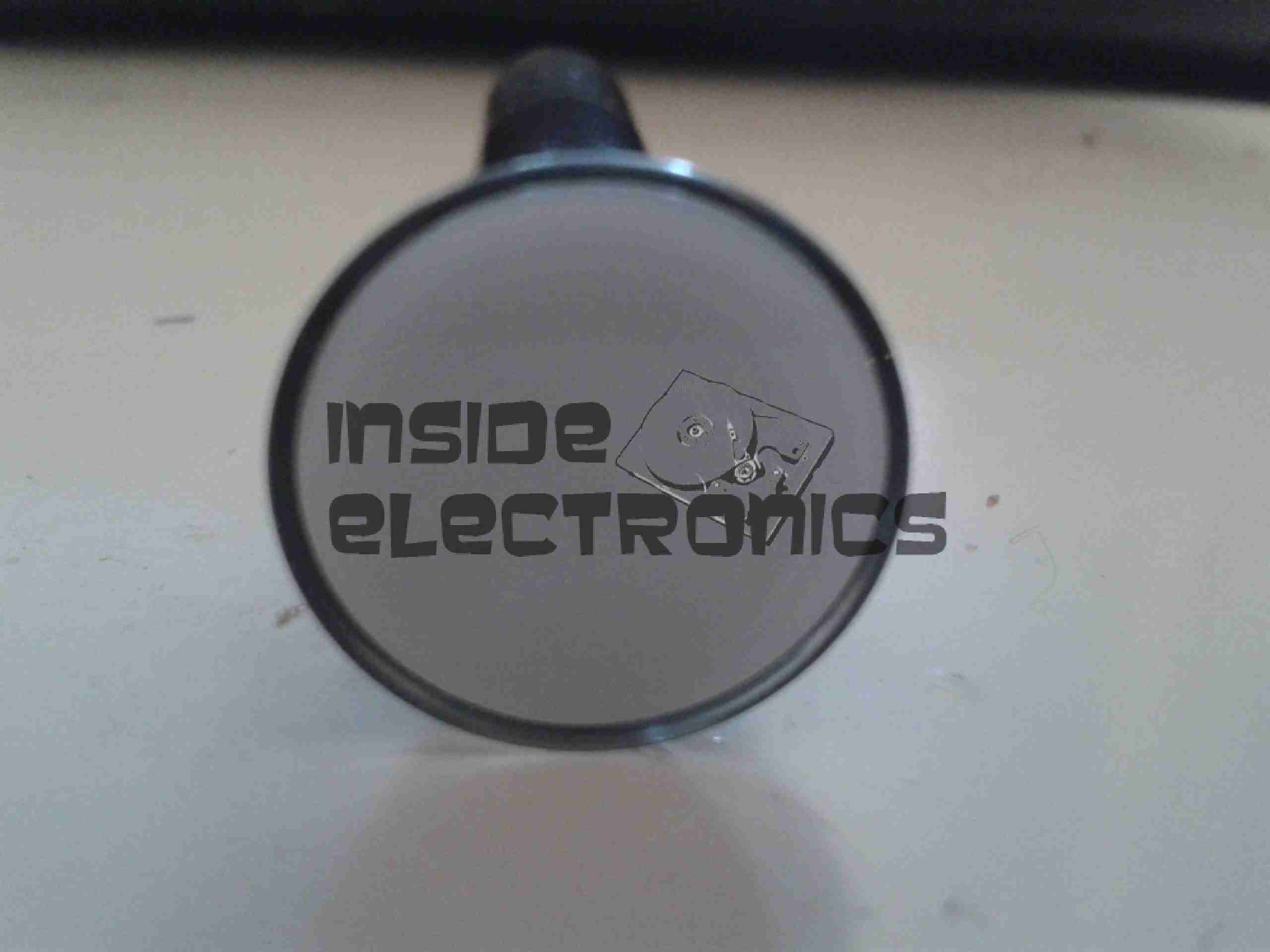
Phosphor Screen
This screen is just a little bigger than a UK 5p piece! A marvel of precision engineering.
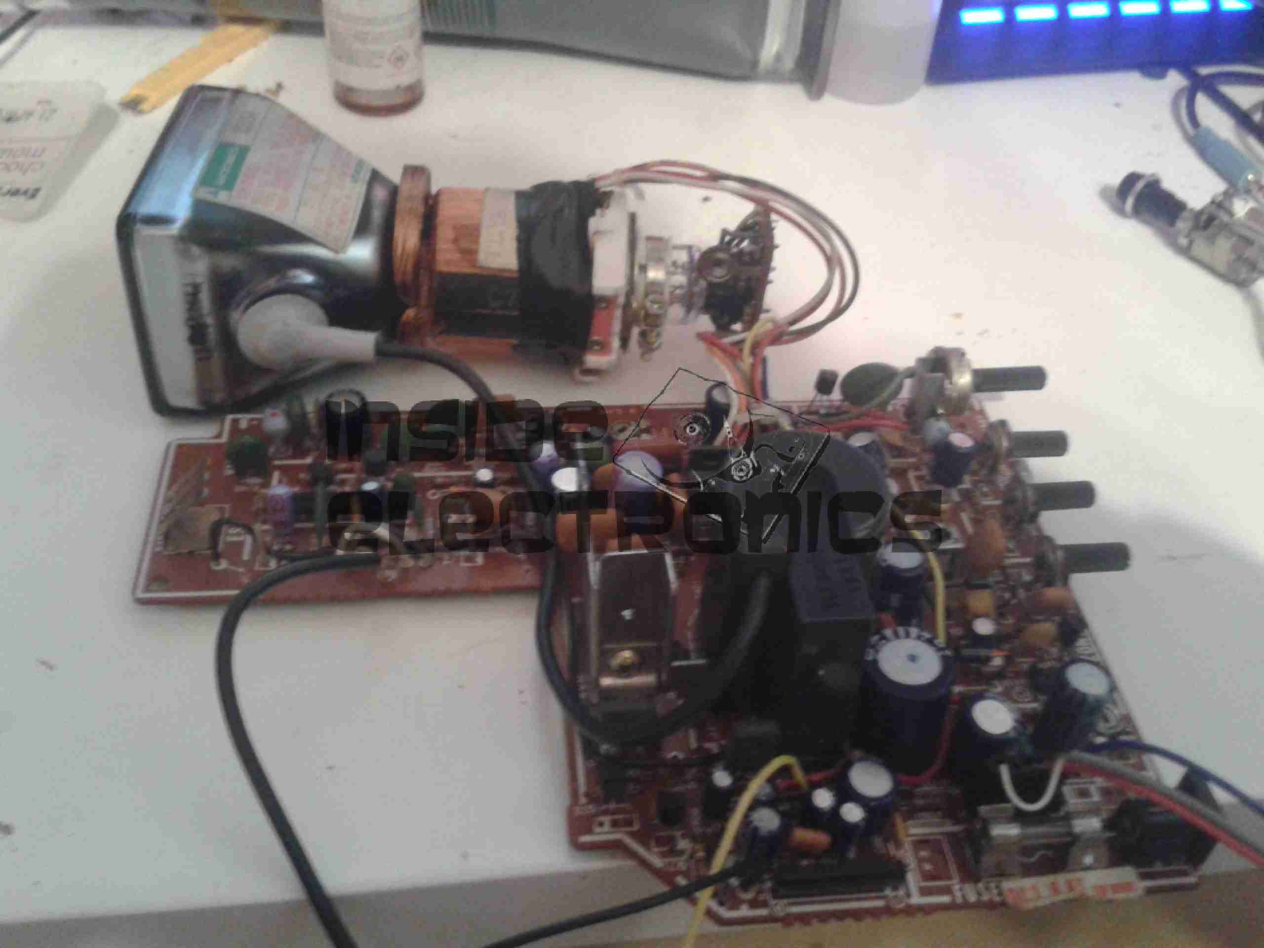
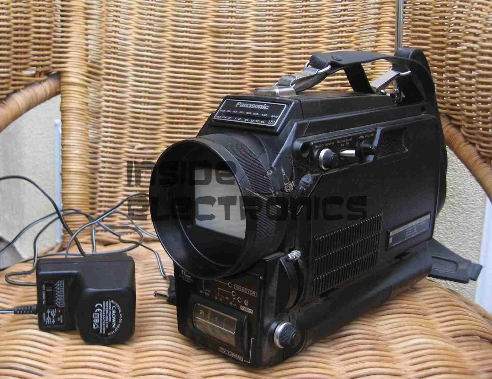
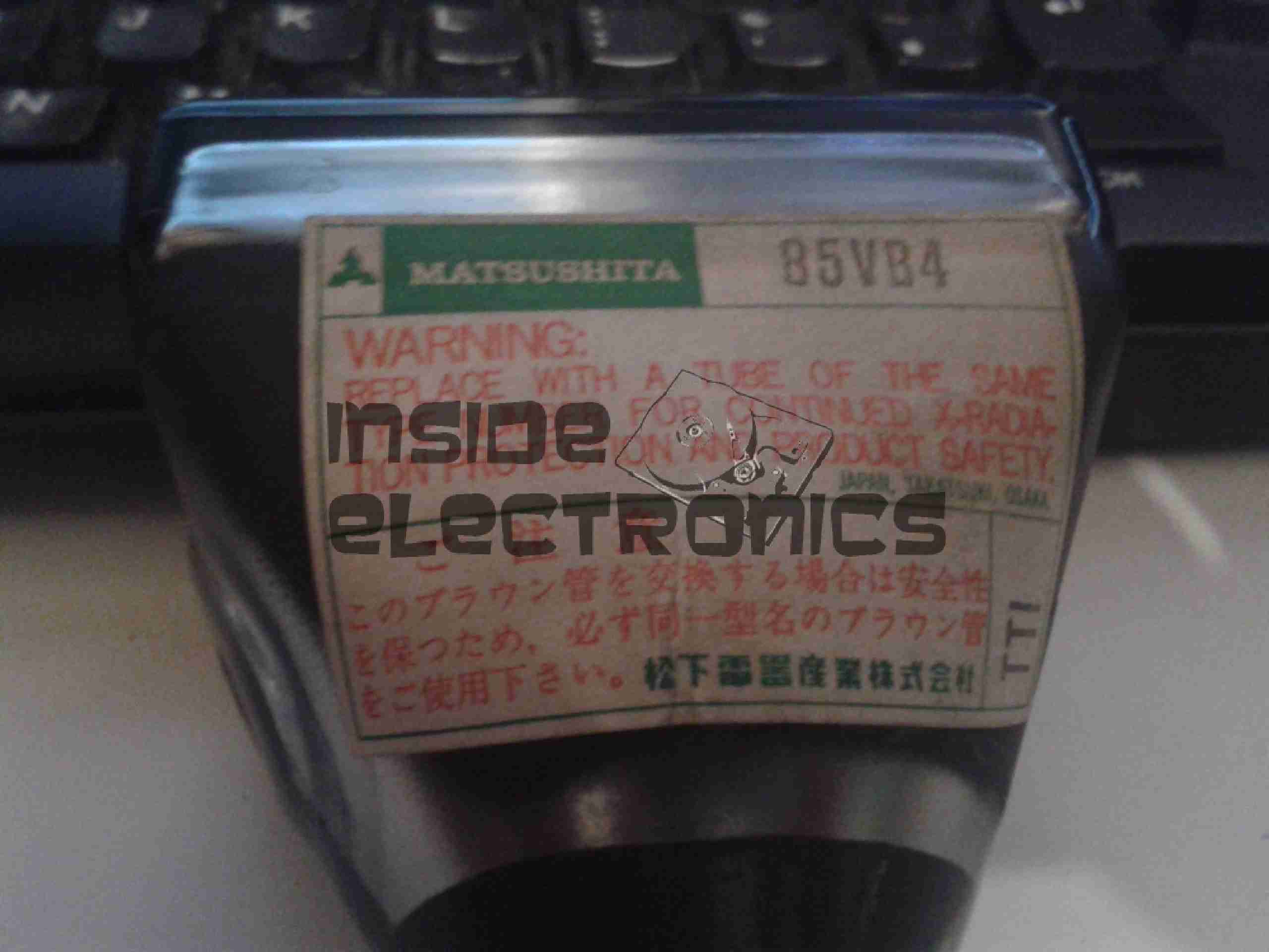
I recently managed to score a 3″ B&W portable TV on eBay, a Panasonic TR-3000G. As these old units are now useless, thanks to the switch off of analogue TV signalling, I figured I could find a composite signal internally & drive the CRT with an external source.
Panasonic TR-3000G
Here’s the TV in it’s native state. Running from 9v DC, or 6 D size cells. I’m guessing from somewhere around the 1970’s. Here is the CRT & associated drive circuitry, removed from the casing:
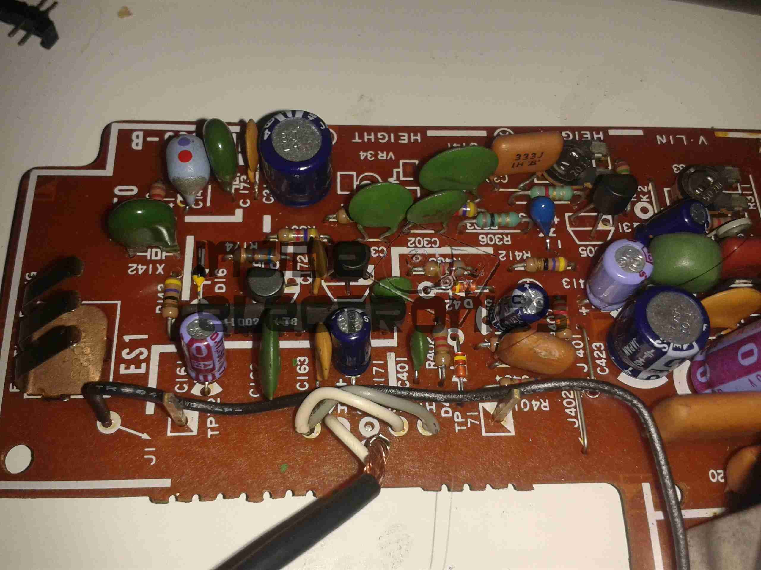
CRT Module
After dissecting the loom wiring between the CRT board & the RF/tuner board, I figured out I had to short out Pins 1,2 & 5 on the H header to get the CRT to operate straight from the power switch. This board also generates the required voltages & signals to drive the RF tuner section. I have removed the loom from this, as the PCB operates fine without. It doesn’t seem to be fussy about power input either: it’s specified at 9v, but seems to operate fine between 7.5v & 14.5v DC without issue.
Video Connections
Tracing the wiring from the tuner PCB revealed a length of coax snaking off to the section marked Video/Sync. I successfully found the composite input!
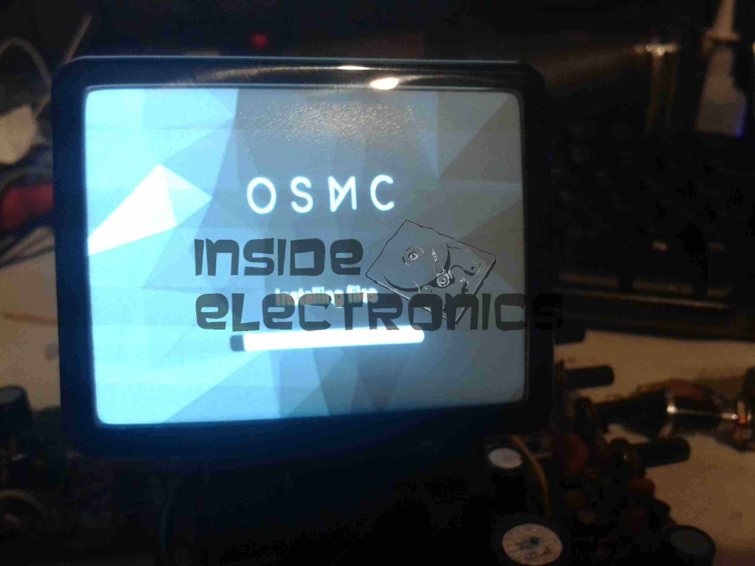
Running OSMC
A quick bit of wiring to a Raspberry Pi, & we have stable video! For such an old unit, the picture quality is brilliant, very sharp focus.
Matsushita 85VB4 CRT
Closeup of the CRT itself. I haven’t been able to find much data on this unit, but I’m guessing it’s similar to many commercial viewfinder CRTs.
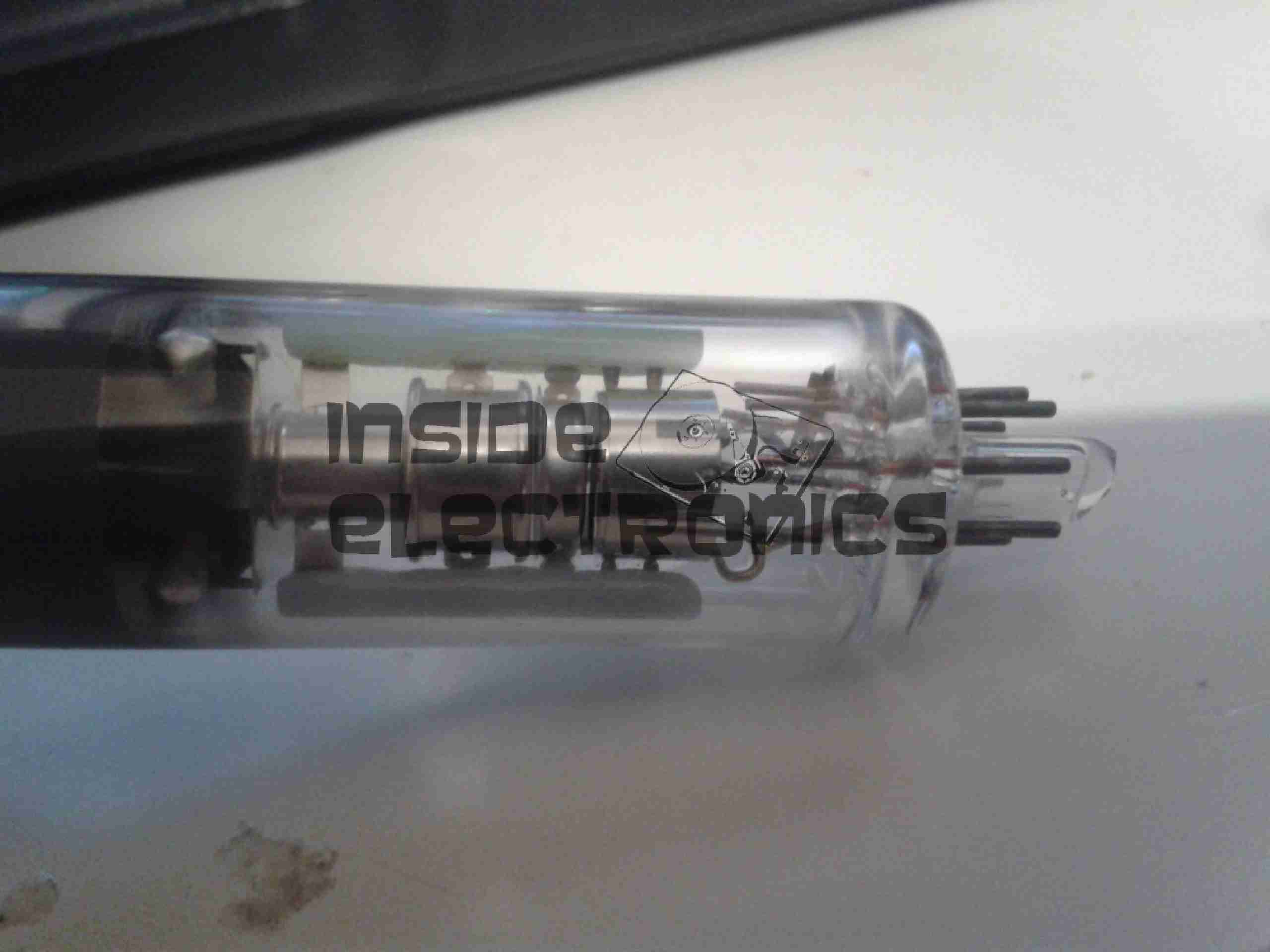
Electron Gun Closeup
Amazingly, there isn’t a single IC in the video circuitry, it’s all discrete components. This probably accounts for the large overall size of the control PCB. Viewfinder CRTs from a few years later on are usually driven with a single IC & a few passives that provide all the same functions.
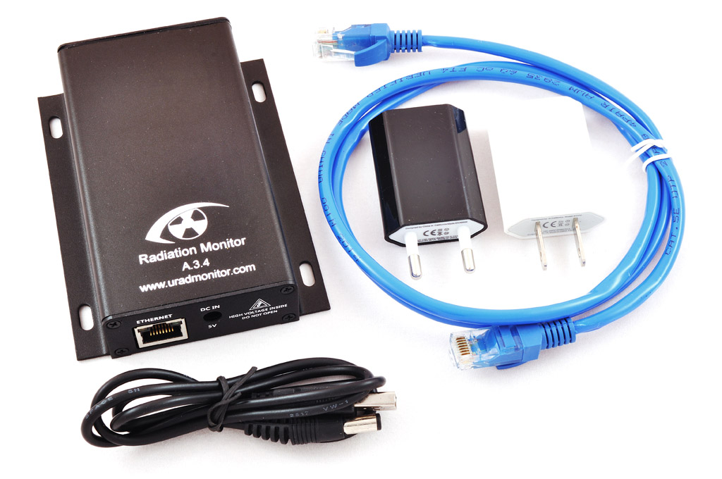
It’s official. I’m now part of the uRadMonitor network, & assisting in some of the current issues with networking some people (including myself) have been having.
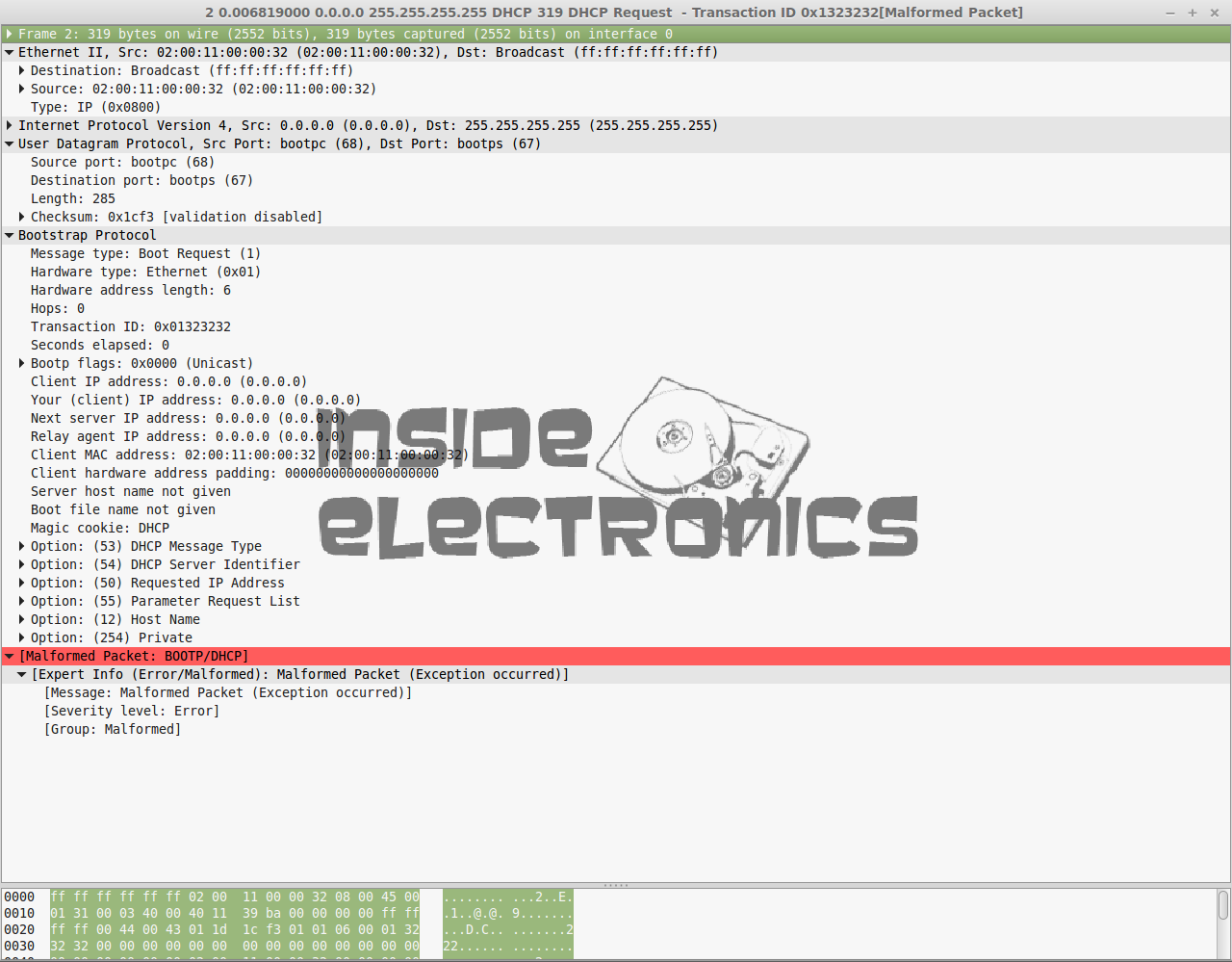
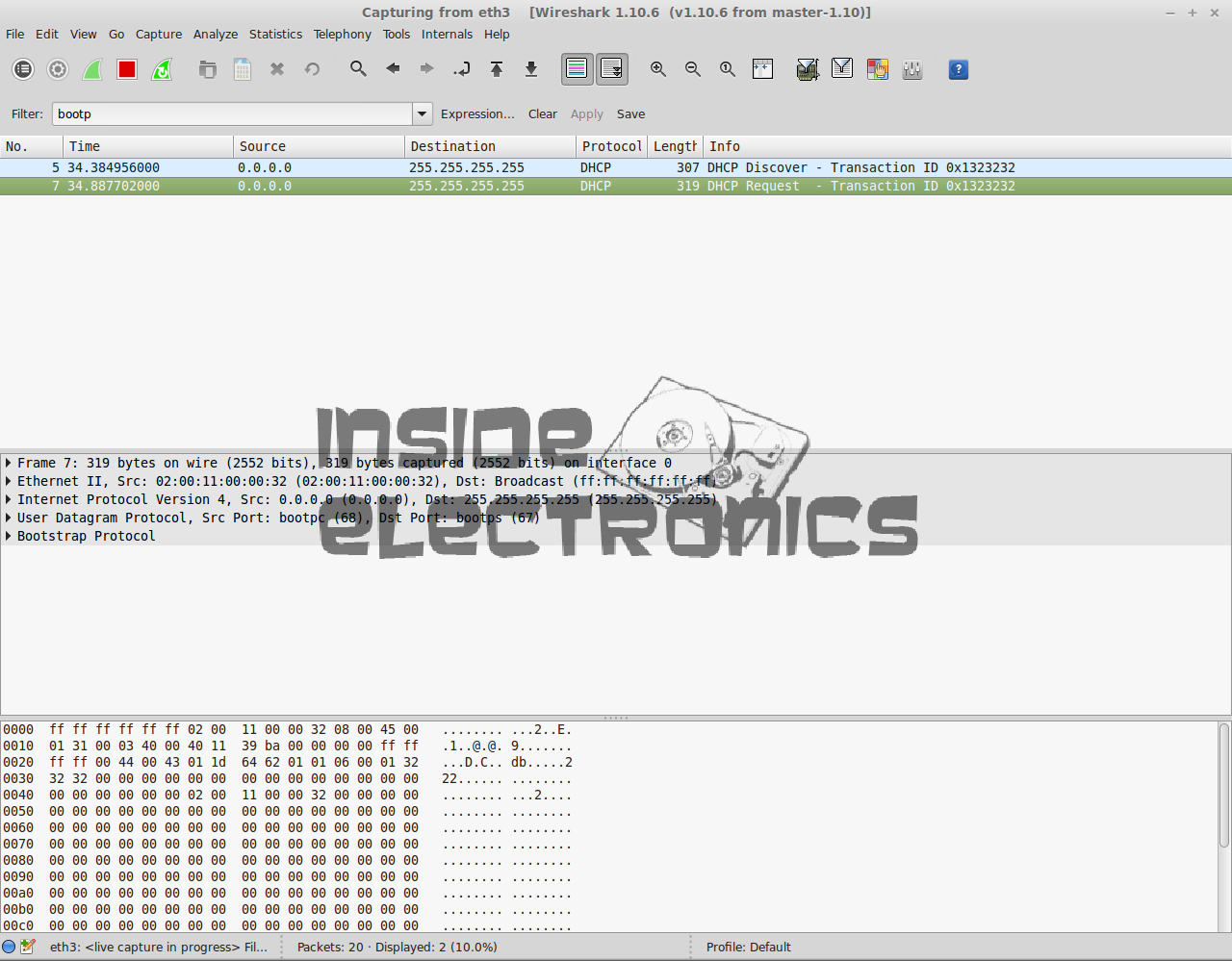
It seems that the uRadMonitor isn’t sending out technically-valid DHCP requests, here is what Wireshark thinks of the DHCP on my production network hardware setup:
WireShark Screencap
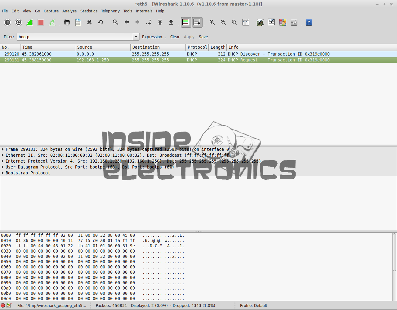
As can be seen, the monitor unit is sending a DHCP request of 319 bytes, where a standard length DHCP Request packet should be ~324 bytes, as can be seen on the below screen capture.
Valid DHCP
This valid one was generated from the same SPI Ethernet module as the monitor, (Microchip ENC28J60) connected to an Arduino. Standard example code from the EtherCard library was used to set up the DHCP. The MAC address of the monitor was also cloned to this setup to rule out the possibility of that being the root cause.
My deductive reasoning in this case points to the firmware on the monitor being at fault, rather than the SPI ethernet hardware, or my network hardware. Radu over at uRadMonitor is looking into the firmware being at fault.
Strangely, most routers don’t seem to have an issue with the monitor, as connecting another router on a separate subnet works fine, and Wireshark doesn’t even complain about an invalid DHCP packet, although it’s exactly the same.
Working DHCP
As the firmware for the devices isn’t currently available for me to pick apart & see if I can find the fault, it’s up to Radu to get this fixed at the moment.
Now, for a µTeardown:
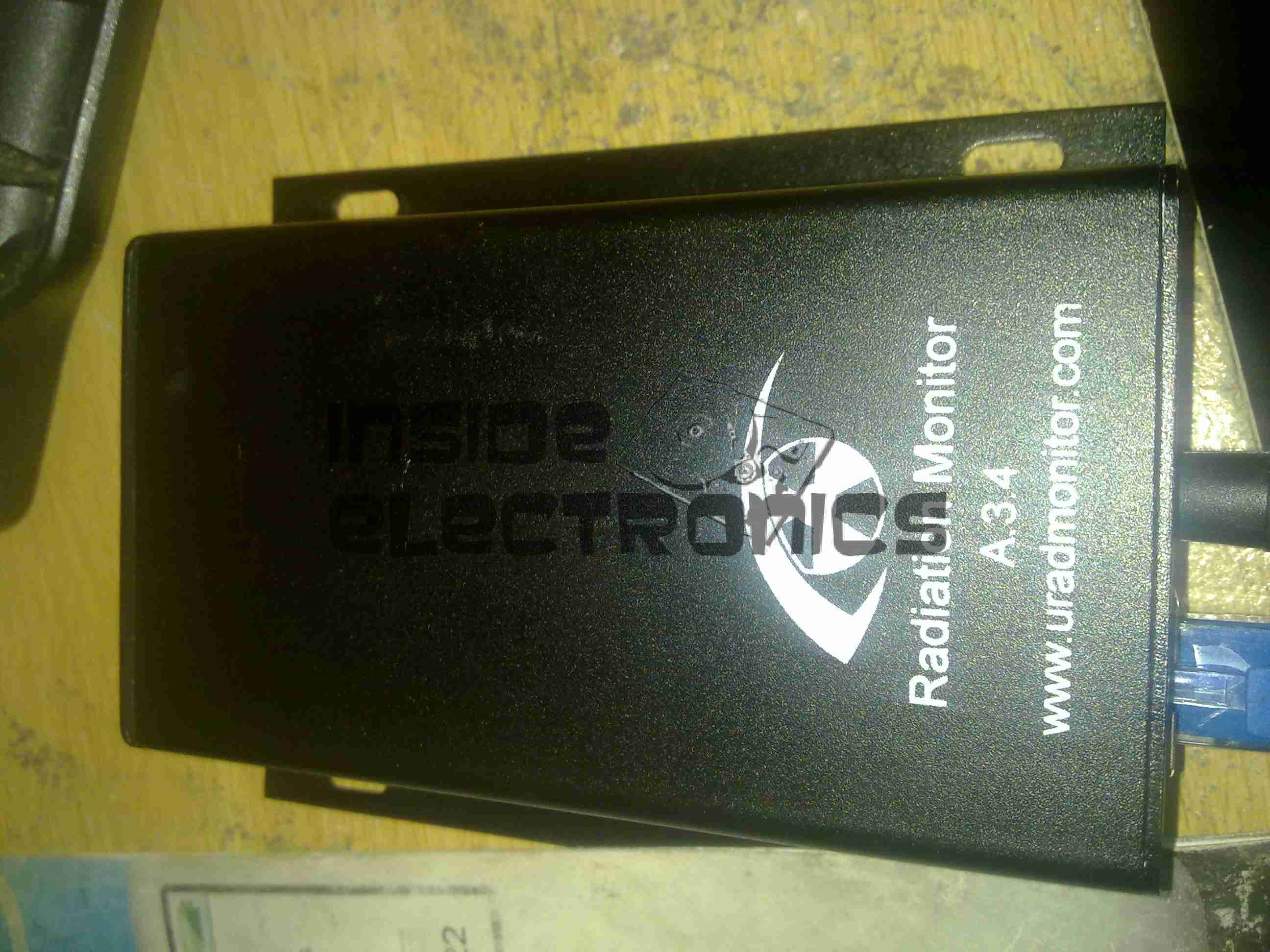
uRadMonitor
Here is the monitor, a small aluminium box, with power & network.
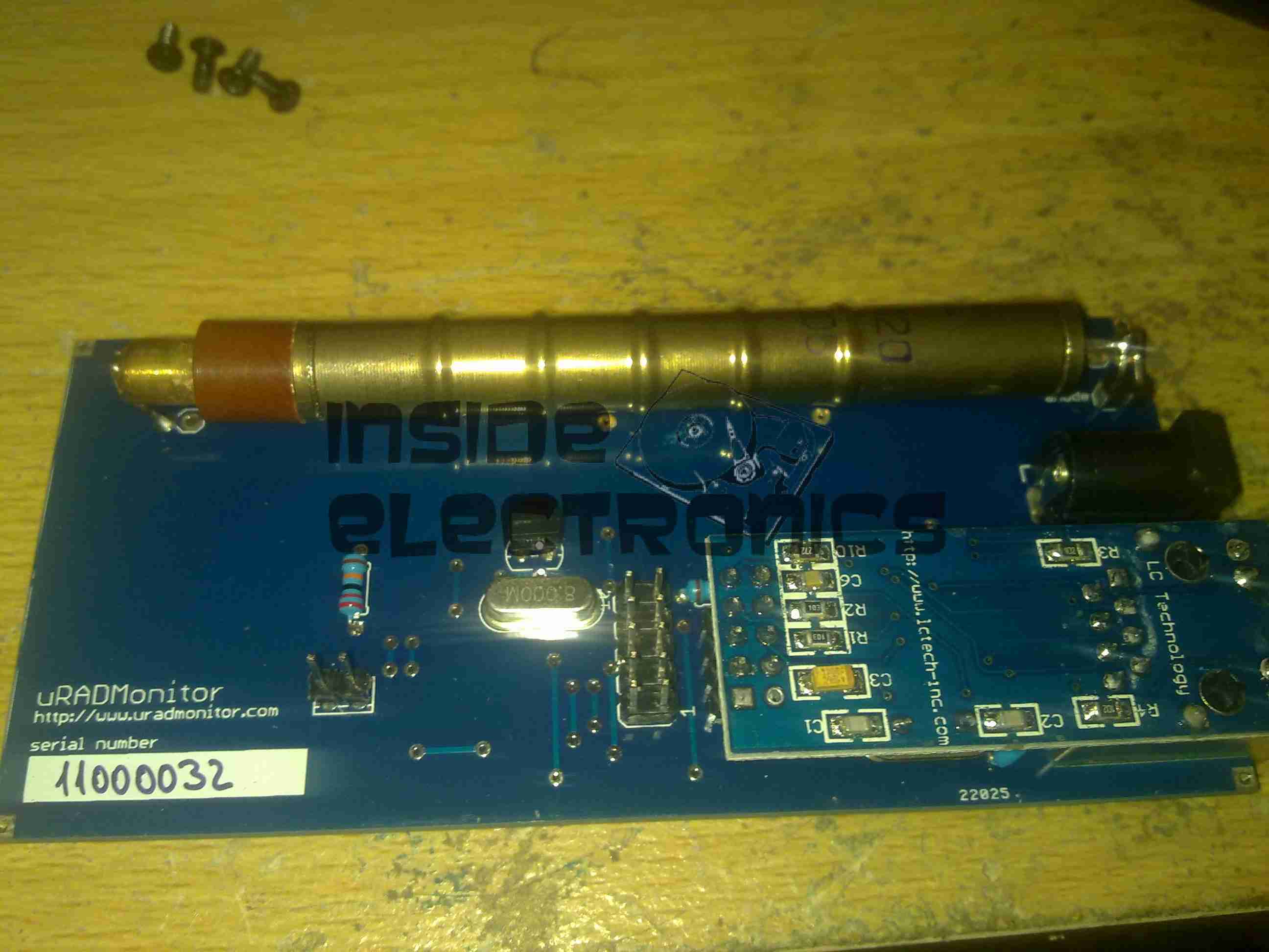
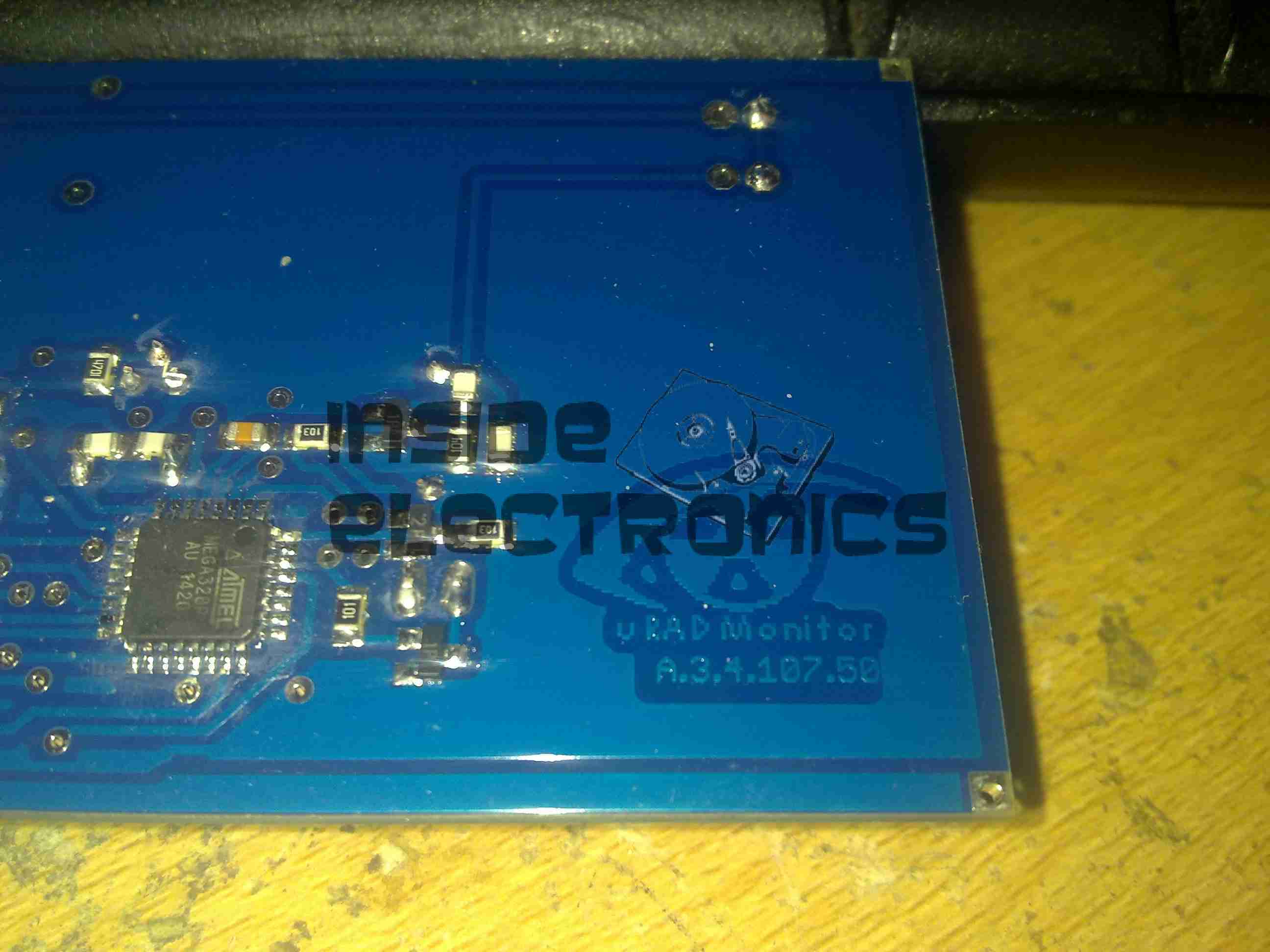
PCB
Removing 4 screws in the end plate reveals the PCB, with the Geiger-Mueller tube along the top edge. My personal serial number is also on the PCB.
The ethernet module is on the right, with the DC barrel jack.
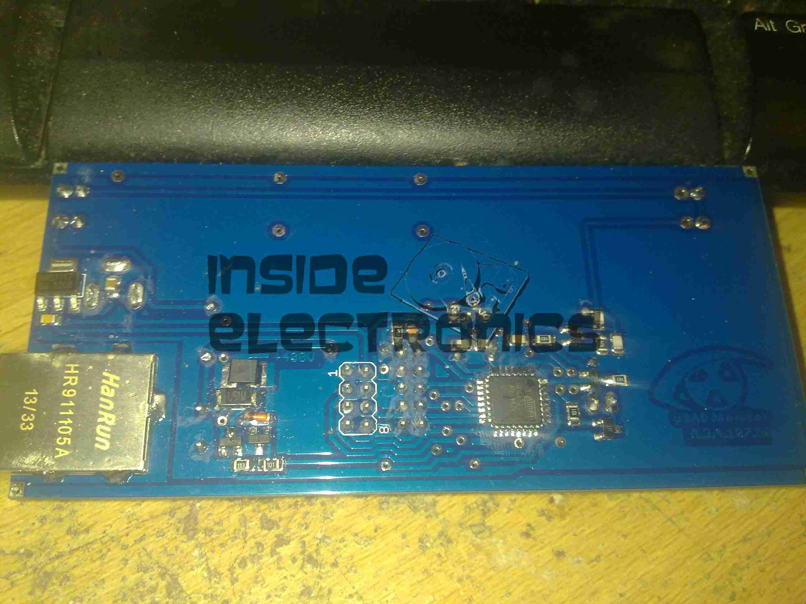
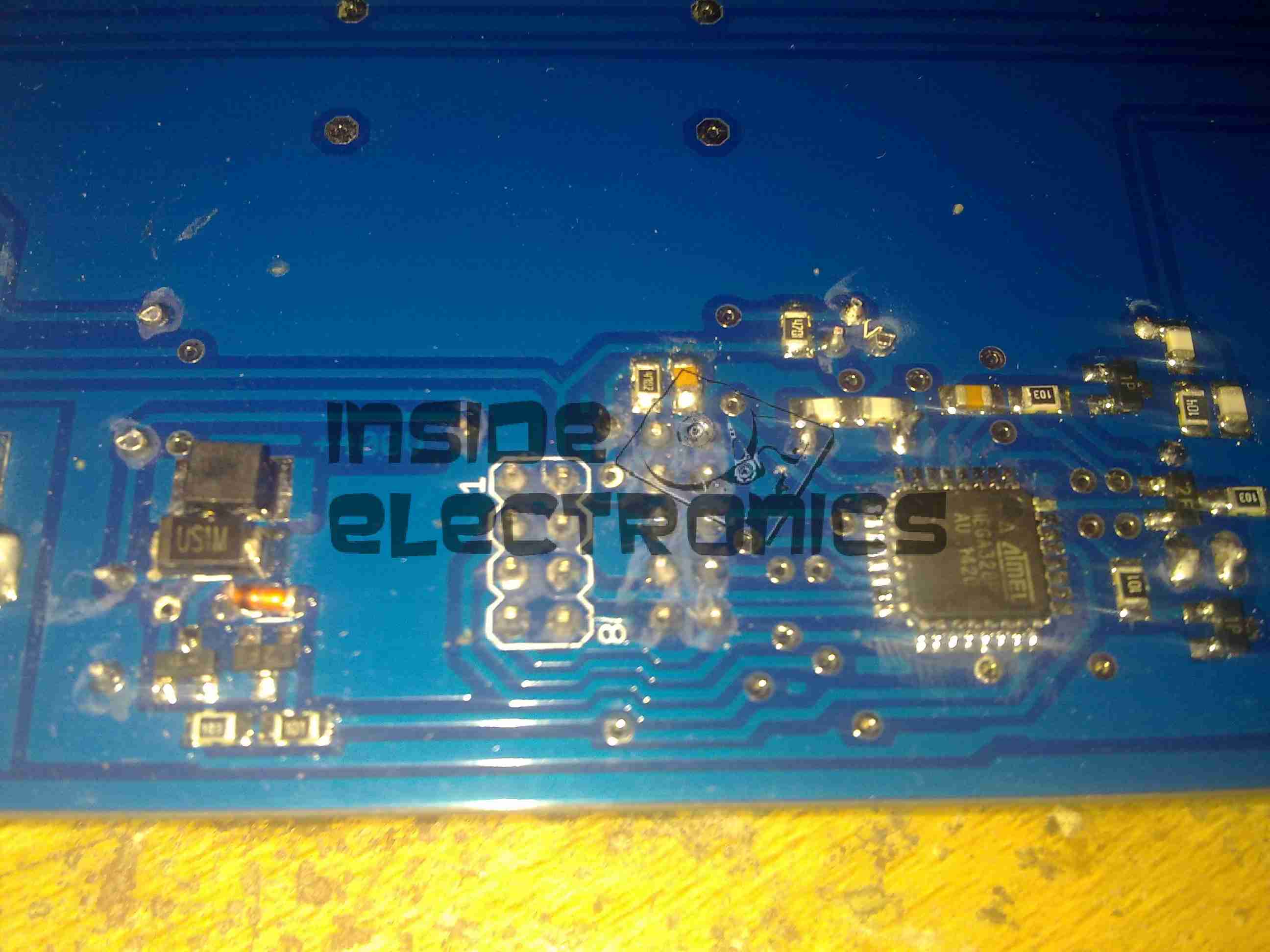
PCB Bottom
Here is the bottom of the PCB, with the control MCU & the tiny high voltage inverter for the Geiger tube.
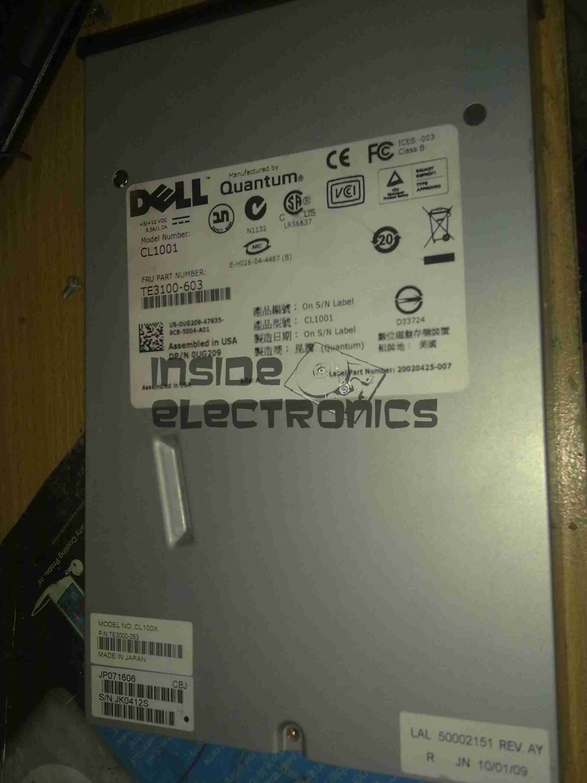
I have recently begun to create an archive of all my personal data, and since LTO2 tape drives offer significant capacity (200GB/400GB) per tape, longevity is very high (up to 30 years in archive), & relatively low cost, this is the technology I’ve chosen to use for my long term archiving needs.
Unfortunately, this drive was DOA, due to being dropped in shipping. This drop broke the SCSI LVD connector on the back of the unit, & bent the frame, as can be seen below.
Broken SCSI
As this drive is unusable, it made for a good teardown candidate.
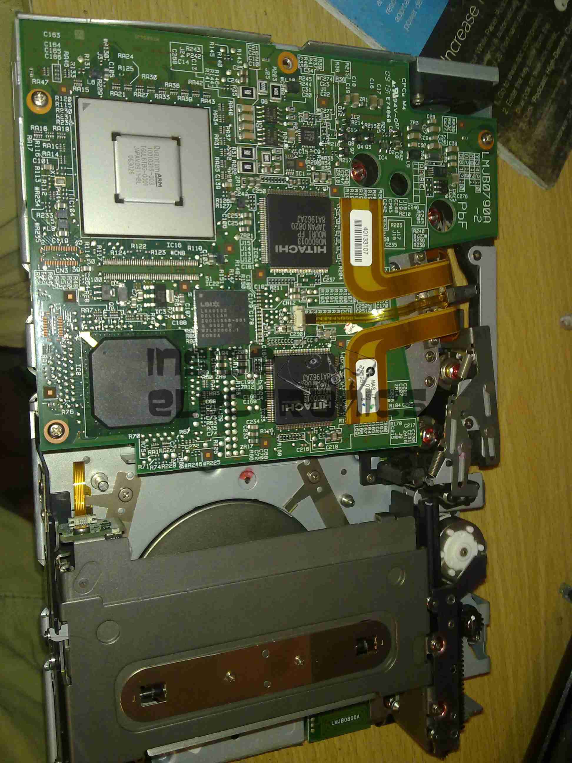
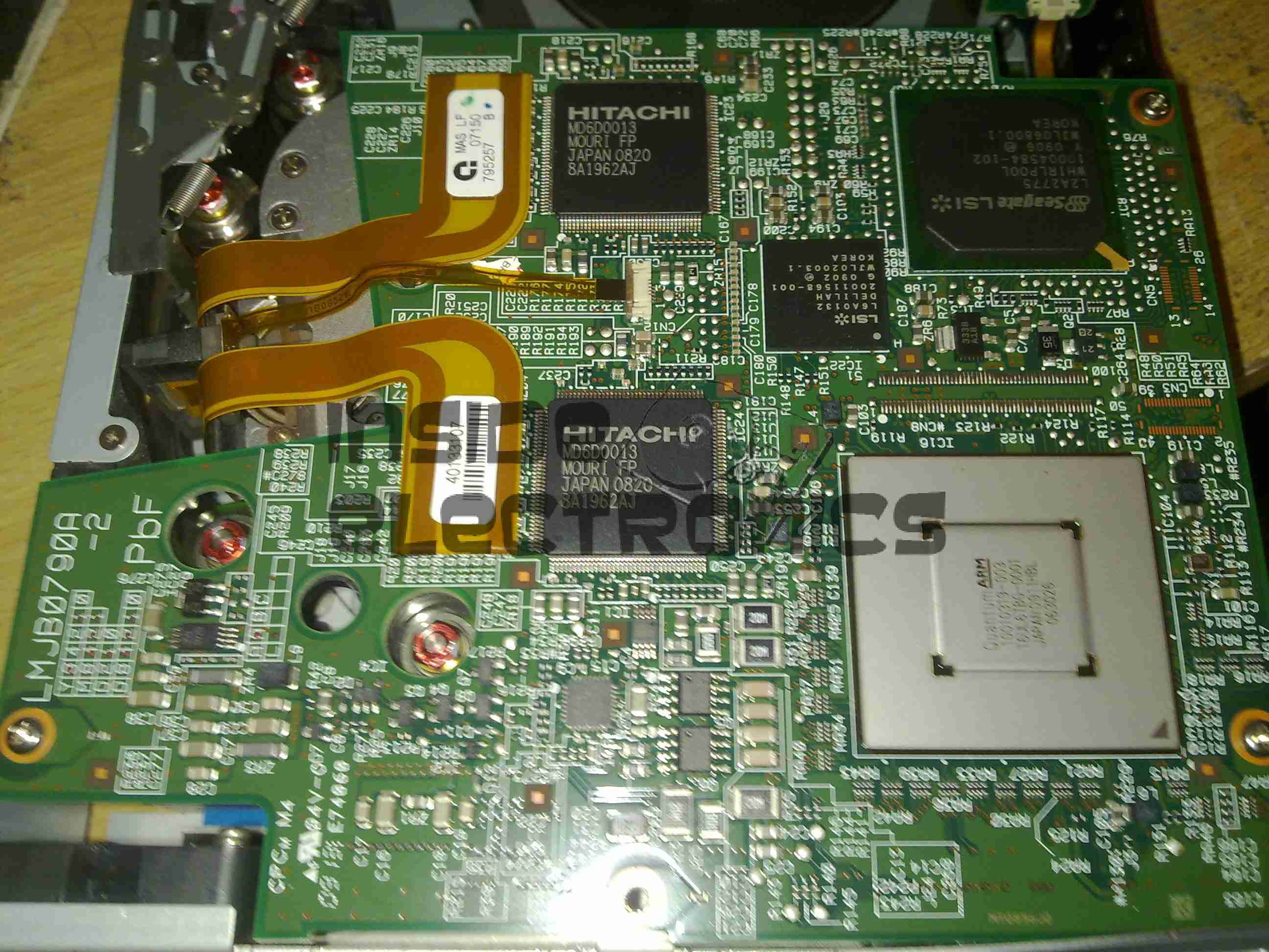
Cover Removed
Here the top cover of the drive has been removed, showing the top of the main logic PCB. The large silver IC in the top corner is the main CPU for the drive. It’s a custom part, but it does have an ARM core.
The two Hitachi ICs are the R/W head interface chipset, while the smaller LSI IC is the SCSI controller.
The tape transport & loading mech can be seen in the lower half of the picture.
Main Logic
Close up of the main logic.
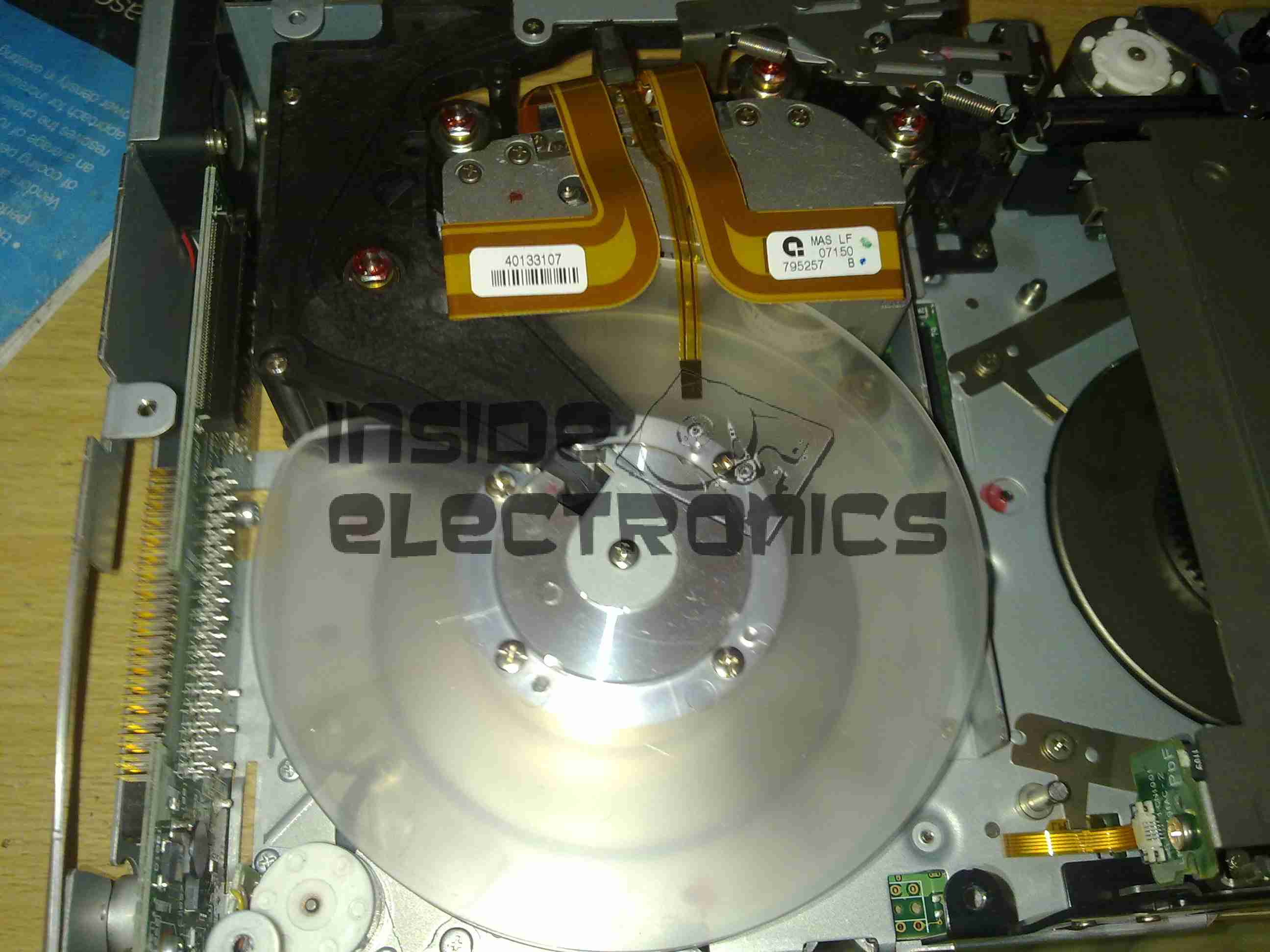
Tape Spool
Here the main logic PCB has been removed, showing the tape take up spool. The data cartridges have only one spool to make the size smaller. When the tape is loaded, the drive grabs onto the leader pin at the end of the tape & feeds it onto this spool.
The head assembly is just above the spool.
Bottom Plate Removed
Bottom of the drive with the cover plate removed. Here the spindle drive motors are visible, both brushless 3-Phase units. Both of these motors are driven by a single controller IC on the other side of the lower logic PCB.
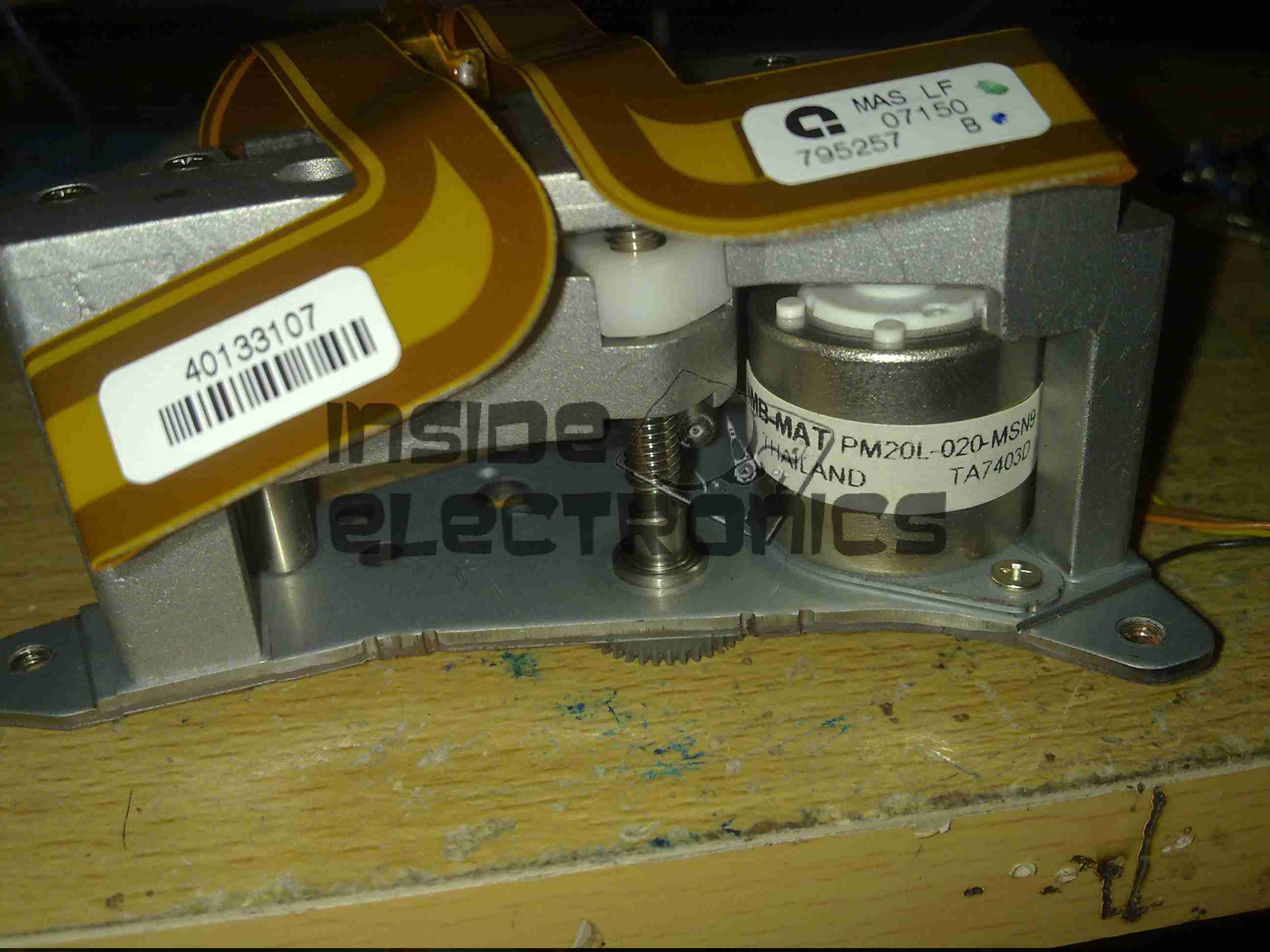
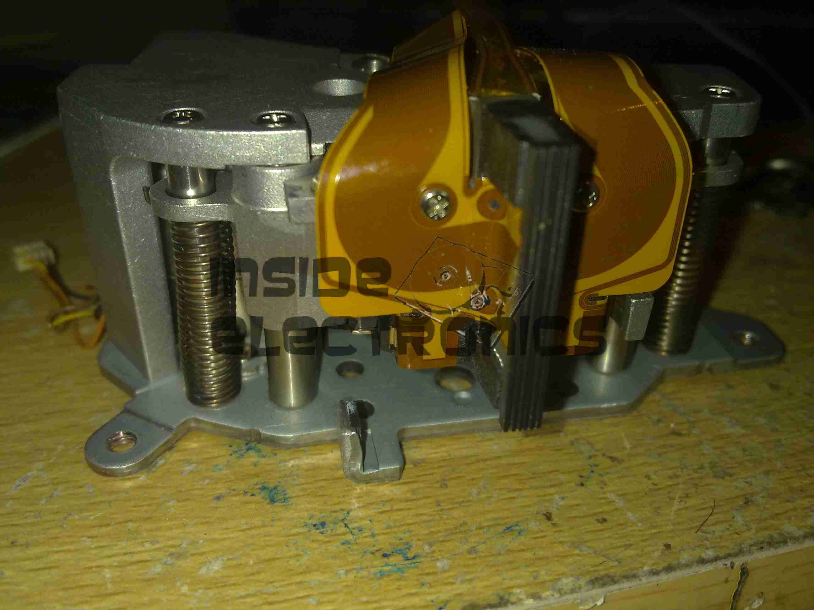
Head Drive Motor
The head is moved up & down the face of the tape by this stepper motor for coarse control, while fine control is provided by a voice coil assembly buried inside the head mount.
Tape Head Assembly
The face of the tape R/W head. This unit contains 2 sets of 8 heads, one of which writes to the tape, the other then reads the written data back right after to verify integrity.
Cartridge Load Motor
The tape cartridge loading motor. I originally thought that this was a standard brushed motor, but it has a ribbon cable emerging, this must be some sort of brushless arrangement.
A replacement drive is on the way, I shall be documenting some more of my archiving efforts & system setup once that unit arrives.
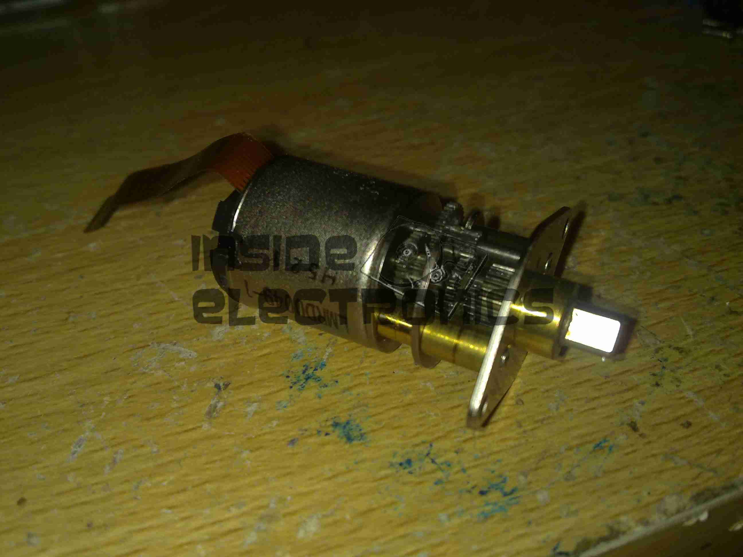
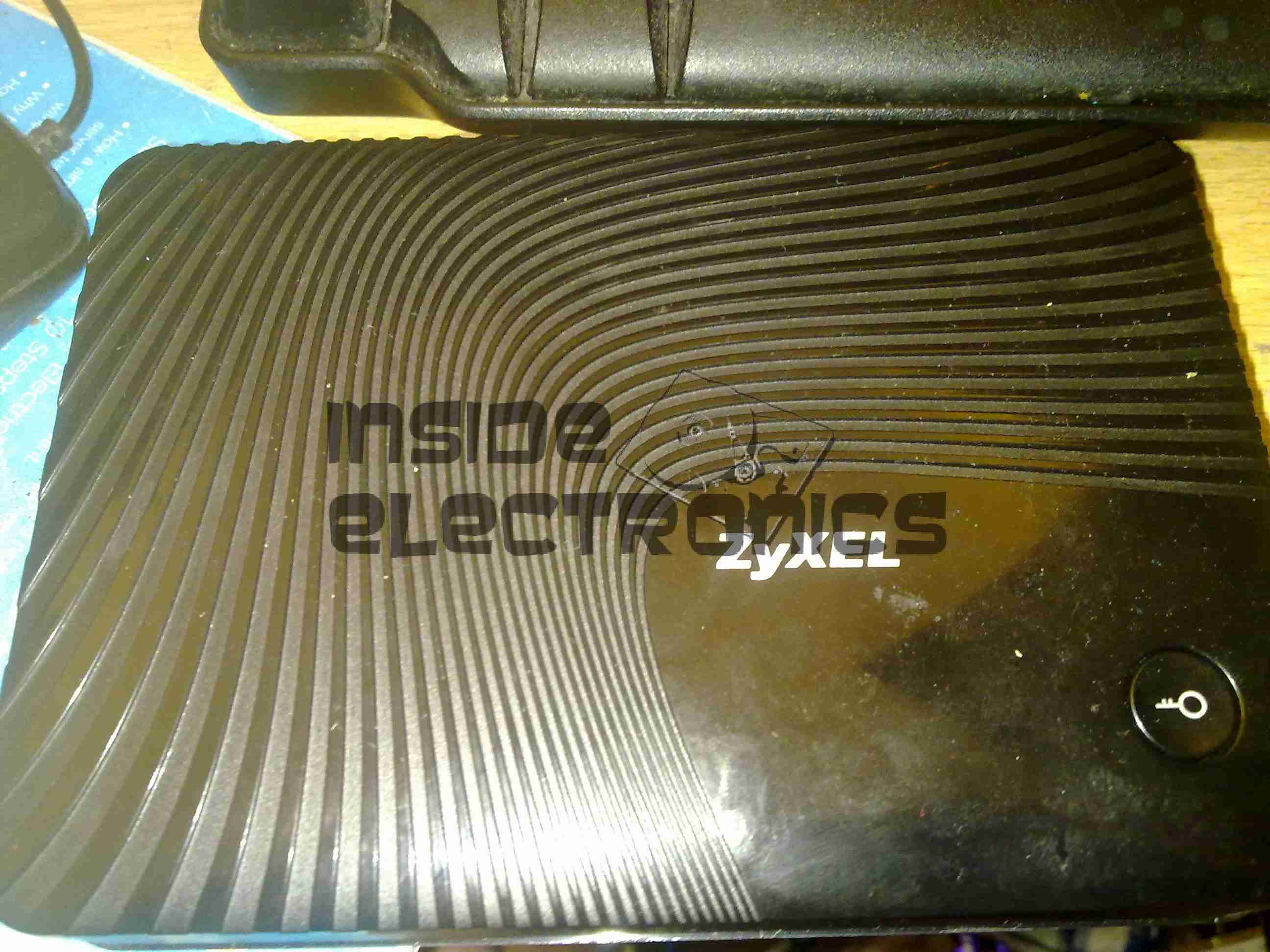
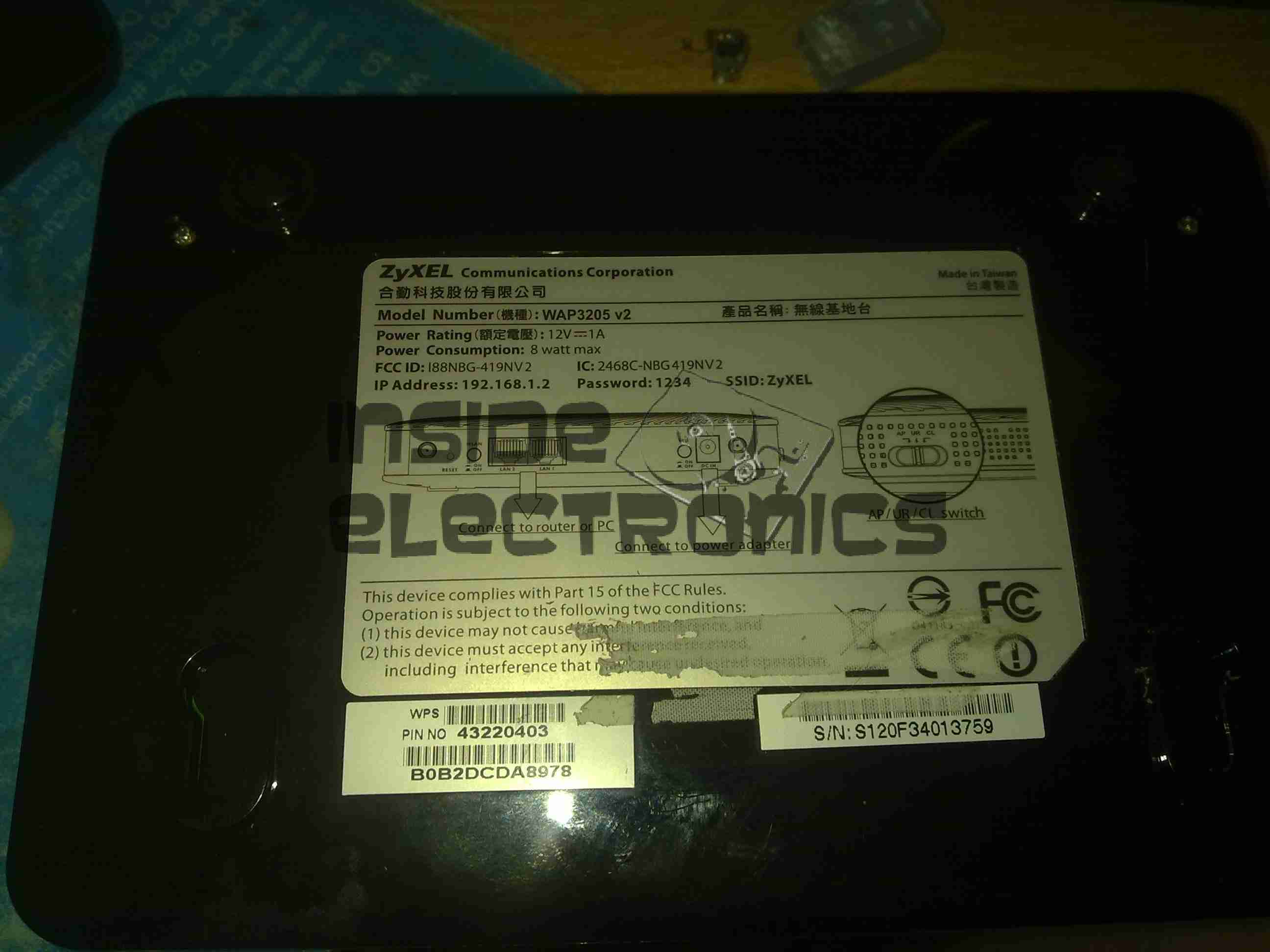
Here is a ZyXel WAP3205 WiFi Access Point that has suffered a reverse polarity event, due to an incorrect power supply being used with the unit.
ZyXEL WAP3205
While most electronic gadgets are protected against reverse polarity with a blocking diode, this unit certainly wasn’t. Applying +12v DC the wrong way round resulted in this:
Blown Switchmode IC (Fuzzy Focus)
That is the remains of the 3.3v regulator IC, blown to smithereens & it even attempted an arson attack. Luckily this was the only damaged component, & I was able to repair the unit by replacing the switching IC with a standalone regulator. (Replacing the IC would have been preferable, if there was anything left of it to obtain a part number from).
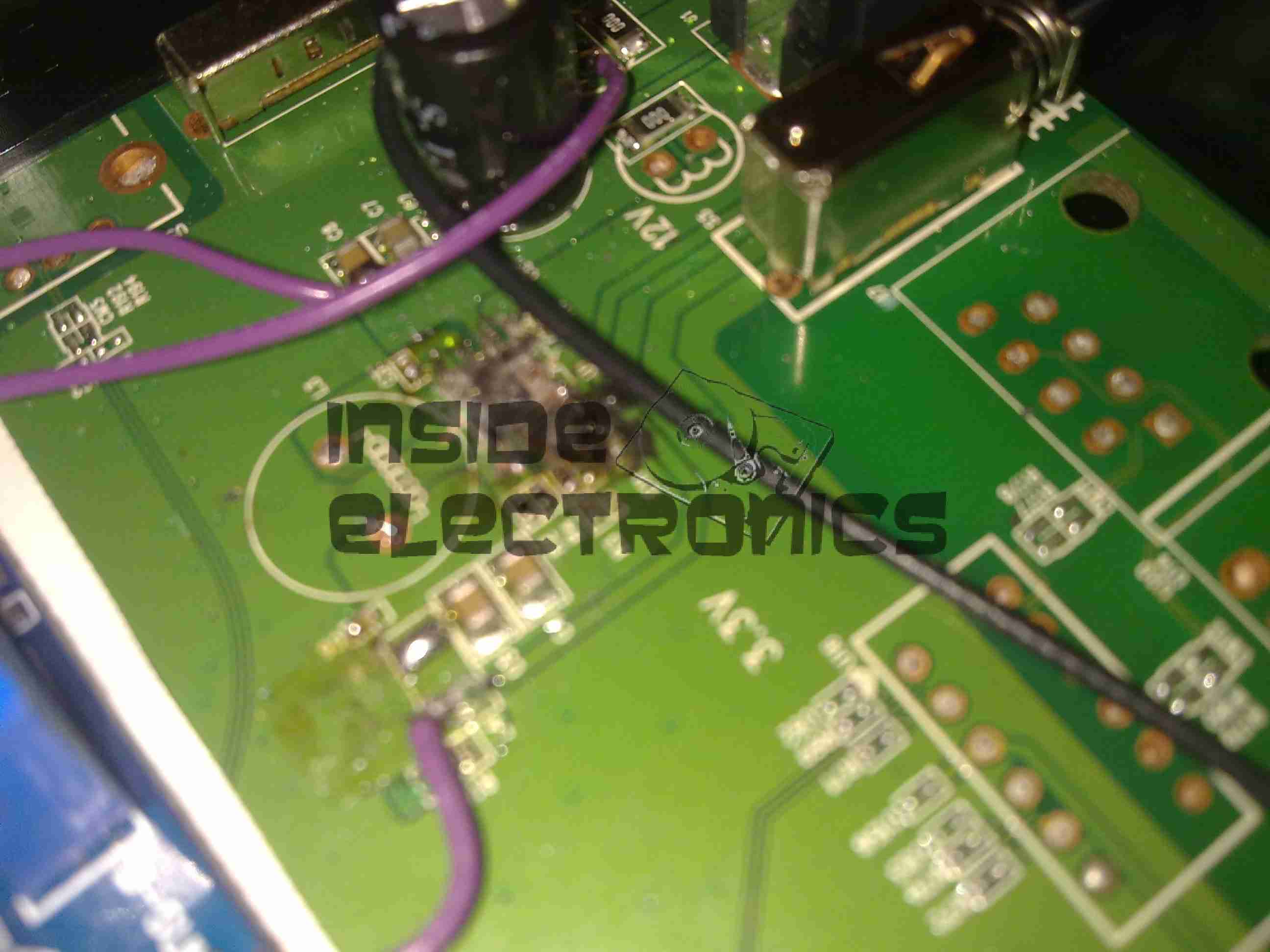
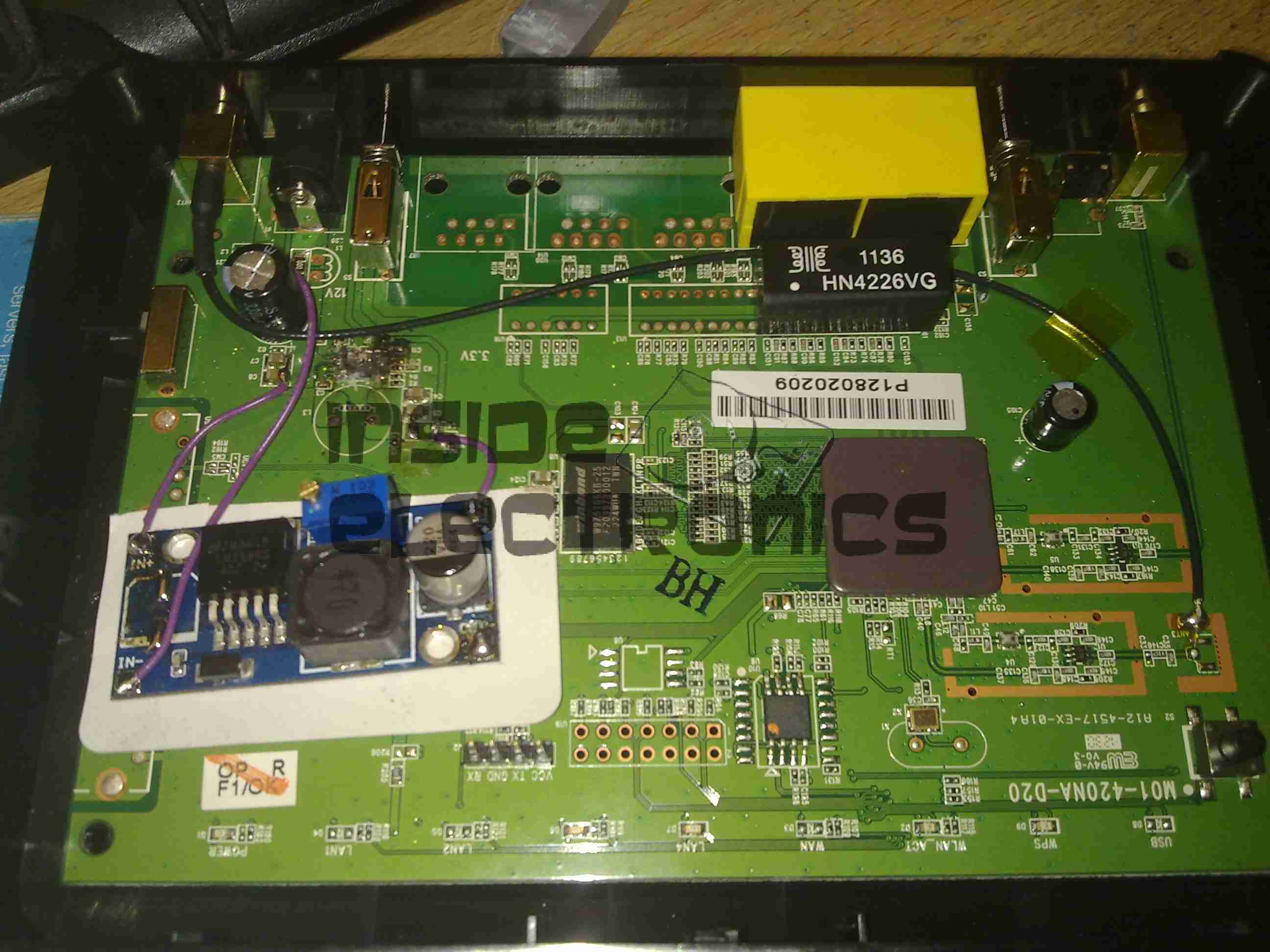
I scraped away the pins of the IC to clear the short on the input supply, removed the switching inductor, & tacked on an adjustable regulator module set to 3.3v. Luckily the voltage of the supply is handily marked on the PCB next to the circuit.
Replacement PSU
Replacement SMPS in place on top of the PCB. The output of the supply is connected to one of the pads of L4 (on my unit just an 0 ohm link), the +12v input is connected to the + rail side of C8 & C7 & the final ground connection is hooked in to the back of the barrel jack.
After this replacement, the unit booted straight up as if nothing had happened. All the logic is undamaged!
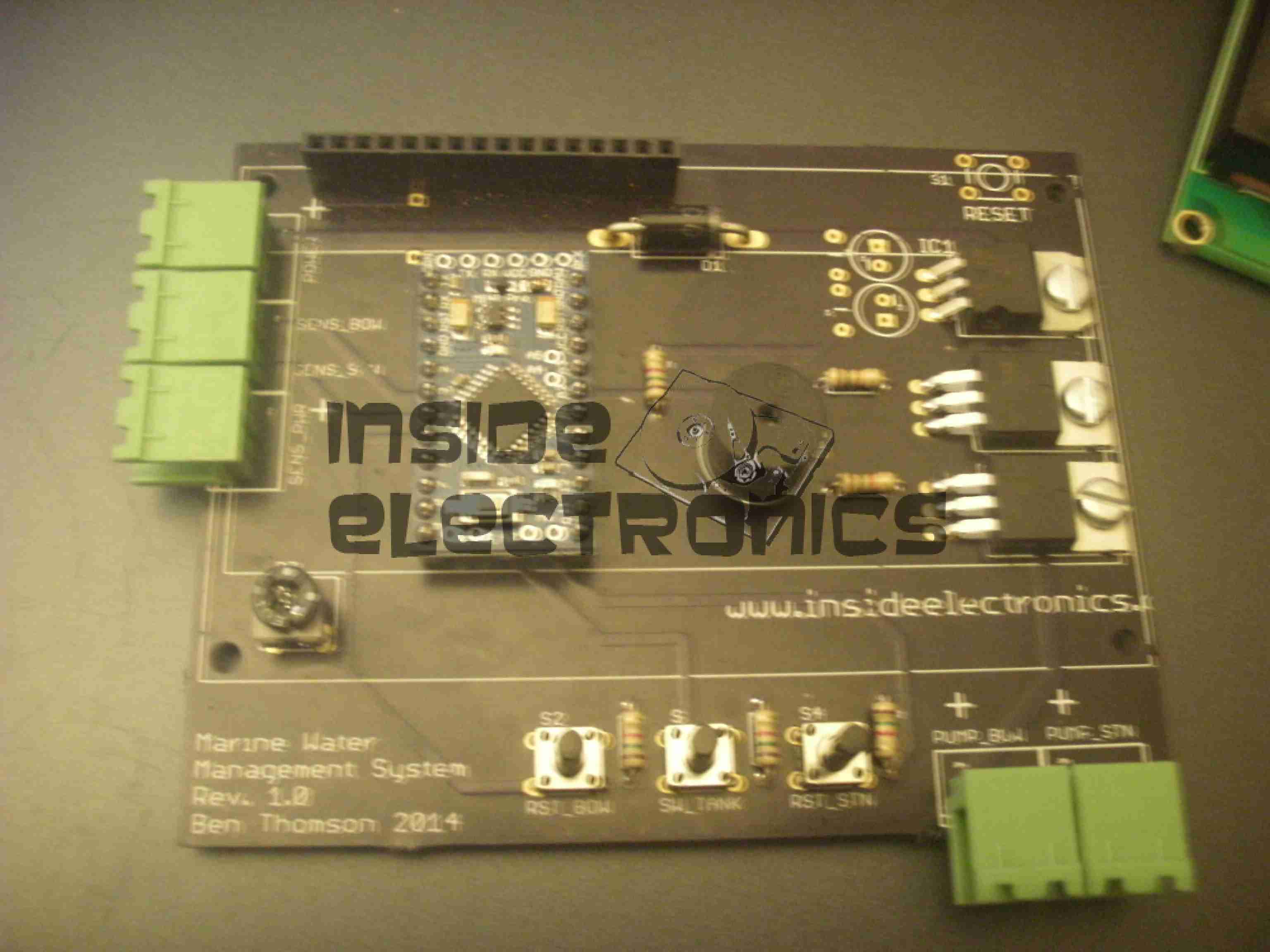
Having two separate water tanks on nb Tanya Louise, with individual pumps, meant that monitoring water levels in tanks & keeping them topped up without emptying & having to reprime pumps every time was a hassle.
To this end I have designed & built this device, to monitor water usage from the individual tanks & automatically switch over when the tank in use nears empty, alerting the user in the process so the empty tanks can be refilled.
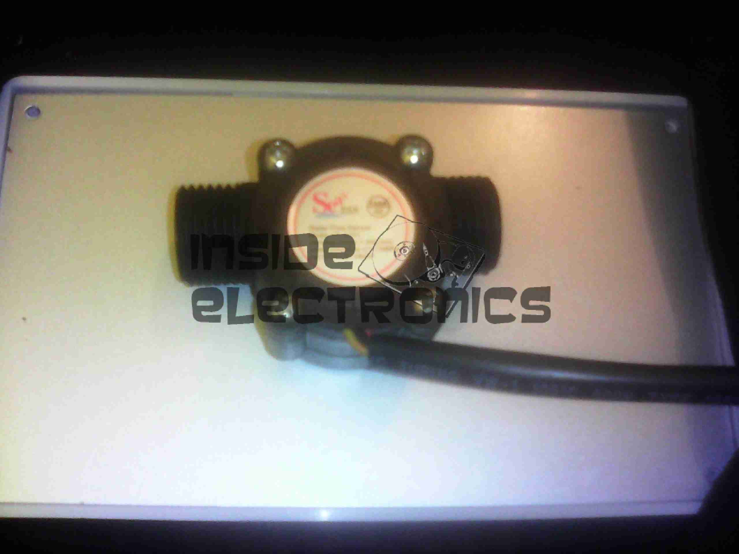
Based around an ATMega328, the unit reads a pair of sensors, fitted into the suction line of each pump from the tanks. The calculated flow is displayed on the 20×4 LCD, & logged to EEPROM, in case of power failure.
Water Flow Sensor
When the tank in use reaches a preset number of litres flowed, (currently hardcoded, but user input will be implemented soon), the pump is disabled & the other tank pump is enabled. This is also indicated on the display by the arrow to the left of the flow register. Tank switching is alerted by the built in beeper.
It is also possible to manually select a tank to use, & disable automatic operation.
Resetting the individual tank registers is done by a pair of pushbuttons, the total flow register is non-resettable, unless a hard reset is performed to clear the onboard EEPROM.
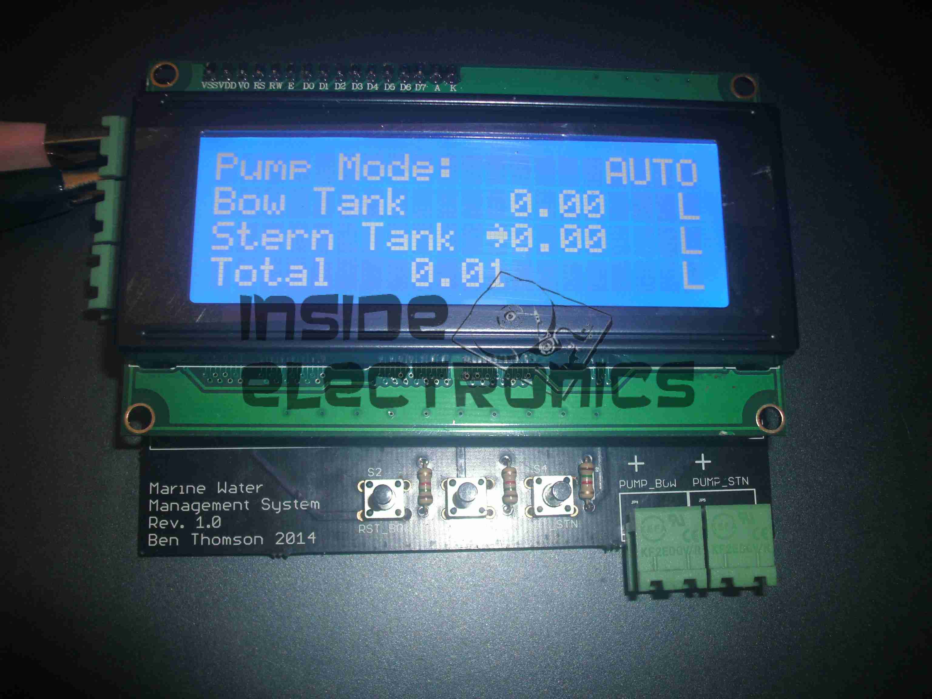
Main PCB
View of the main PCB is above, with the central Arduino Pro Mini module hosting the backend code. 12-24v power input, sensor input & 5v sensor power output is on the connectors on the left, while the pair of pump outputs is on the bottom right, switched by a pair of IRFZ44N logic-level MOSFETS. Onboard 5v power for the logic is provided by the LM7805 top right.
Code & PCB design is still under development, but I will most likely post the design files & Arduino sketch once some more polishing has been done.
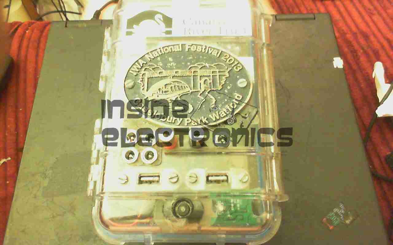
After 13 months of very heavy use at various events, festivals & boat trips, the Li-Po battery pack at the heart of my portable power supply has died.
What initially started as one cell inflating spread to the other cells in the pack over a period of about 3 months, so I have completely replaced the pack with a larger unit.
New Pack
The old pack was an 8.8Ah unit at 12.6v. By using smaller burst capacity cells, I have managed to squeeze in a total of 13.2Ah, still leaving space to spare for an extra 3 cell string along the top.
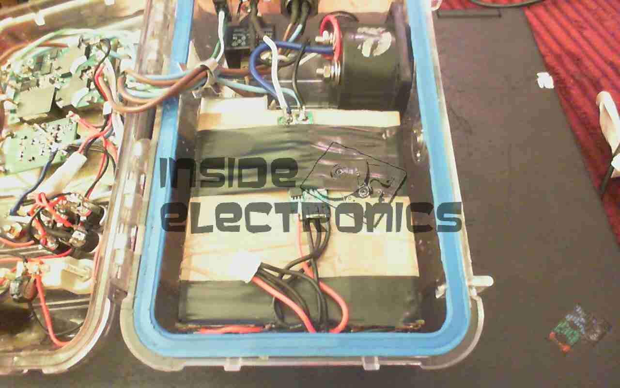
Cell Interconnects
Here is the end of the battery pack, with all the cell interconnects. There are 3 2.2Ah cells in series to give the 12.6v terminal voltage, with 6 of those strings in parallel to give the total Ah rating.
A new charging circuit will be implemented to better handle the volatile chemistry of Li-Po cells, hopefully this will result in the pack lasting longer than a year!
The new higher capacity will hopefully help with power requirements at future events, still being charged during the day by a 24W solar panel, but at night will have to cope with charging two smartphones, two eCigs & running a few watts of LED lighting.
The trial-by-fire will be this year’s Download Festival in June, when I will be operating off-grid for 6 days.
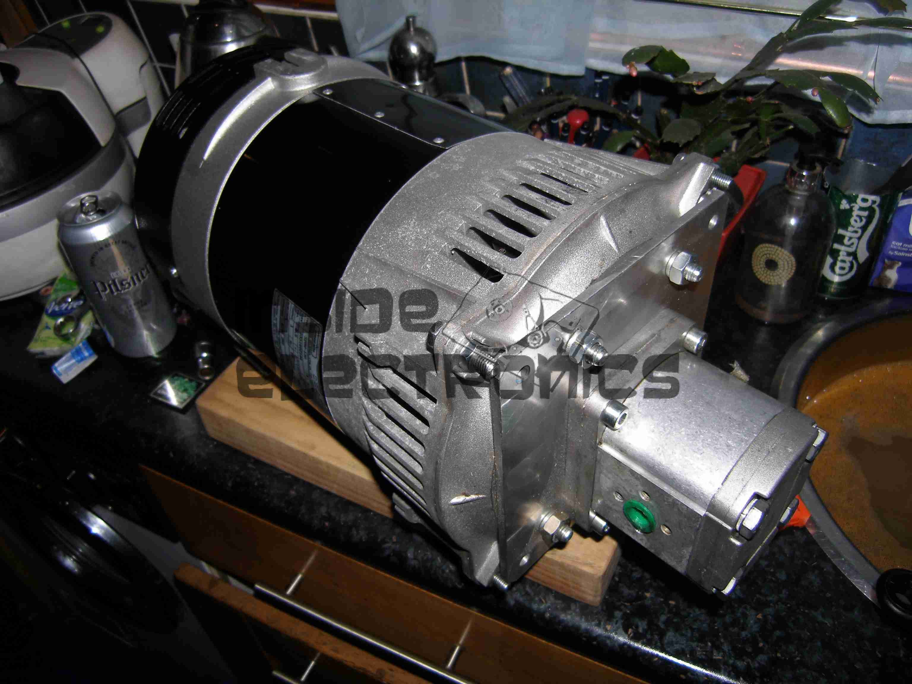
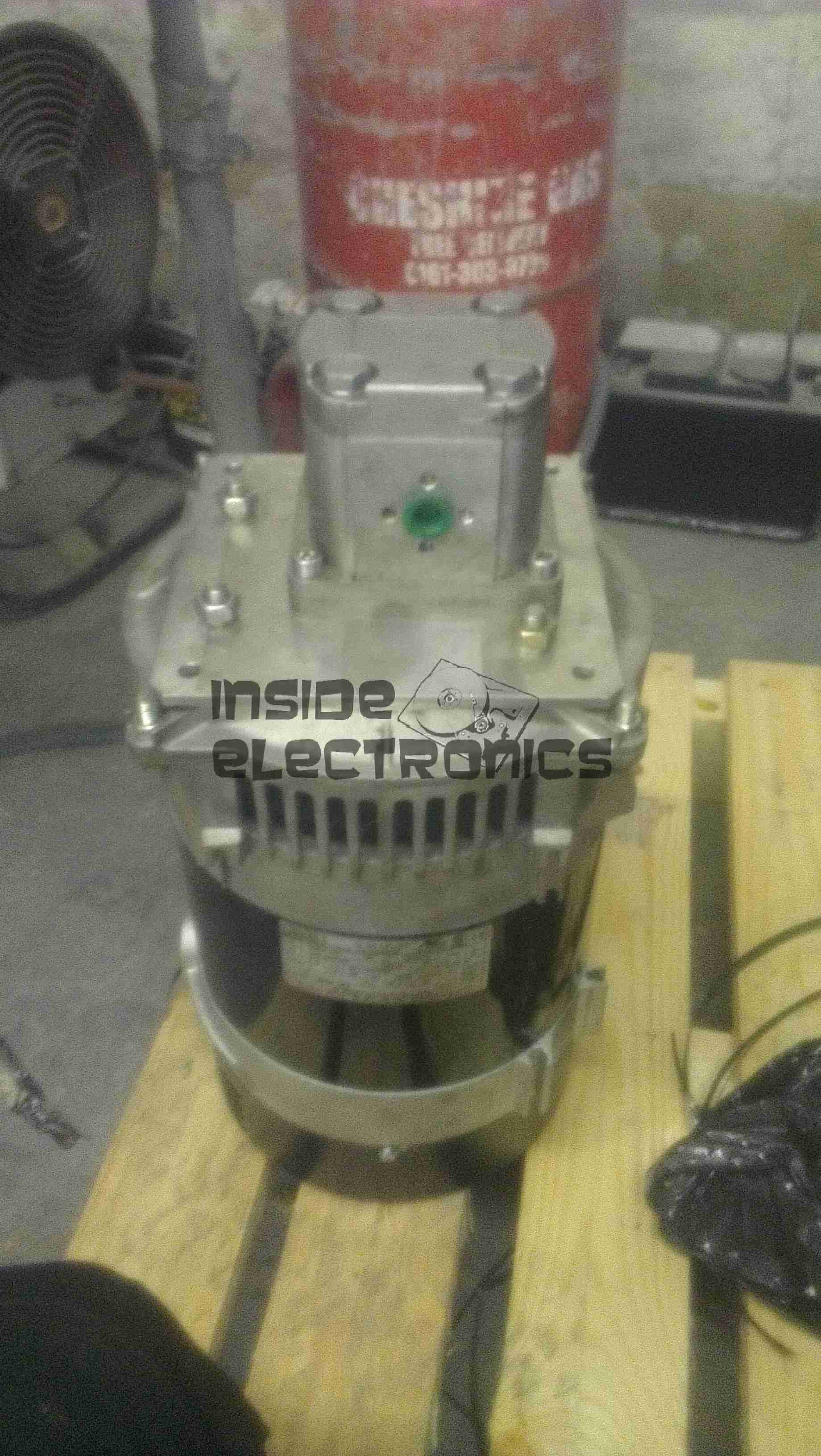
To accompany the previous two posts about hydraulic generators & their components, here is the actual generator unit itself.
Rated at 8.5kVa 230v AC, this will providea mains supply while the narrowboat is away from her home mooring.
This unit will be attached to the side of the hull in the engine room on rubber vibration isolation mounts, behind the main hydraulic oil tank & is driven from the small gear pump attached to the back of the main propulsion hydraulic pump unit.
Operating pressure is 175 bar, 21L/m flow rate to achieve the 3,000RPM rotor speed for 50Hz mains frequency.
While sourcing the main propulsion hydraulic system for nb Tanya Louise in the summer, we thought that it would be convenient to have an on board generator that didn’t require dragging off the boat & highly explosive petrol to operate.
As the hydraulics were already being fitted, we decided to add a hydraulically driven generator to solve this issue.
And this is where the problems began…
We were referred to Mike Webb of hydraulicgenerators.co.uk to supply the equipment required for this part of the project, this was to include the alternator itself, hydraulic motor to drive the alternator, the required adaptor plates to mate the motor to the generator head & a control valve block to regulate the oil flow & pressure to the motor.
After a phone call to Mike on 16-07-2013 to discuss our requirements, we settled on a system. I received the following E-Mail the next day from Mike:
Good morning, reference our conversation, Martin from BSP has given me details as to what he will be supplying, on that basis and in light of the special price I have offered, this is what I propose to supply,
1 off New 8kVa – 7kW Hydraulic driven generator 220v single phase 50hz c/w flow control valve, pressure relief valve and on/off solenoid valve, Martin did say that the engine idle is between 1000 and 1200 rpm and max speed is 3600 rpm, valves will be rated accordingly. I have the alternator and parts available now, in order for me to be able to offer this at a significantly discounted price of £ 1.200.00 nett, I will need to utilise the components I have in stock now, so I will need payment asap, delivery will be approx. 7 days, primarily due to the fact that the coupling is fabricated to suit, I can either deliver the unit to you when ready or BSP or hold onto it until everything else is in place. The alternator is a Meccalte S20W that I bought for another customer a few weeks ago, but he cancelled and I don’t have, at this time, anyone else interested in it, so either I do a deal with you at the above price or wait until someone else comes along and wants the unit.
With regards to installation, let me know if you need any help, but it would be best to install when the engine is being installed and the rest of the system hosed up, I assume BSP will be sorting this, in which case I’ll liase with Martin.
I trust that this meets with your approval and look forward to hearing from you.
At this point an order was placed with Mike, & the money transferred so he could begin building the unit for us. As can be seen from the E-Mail, a lead time of 7 days was stated.
After a few phone calls over the following month, firstly being told that the custom parts to mate the generator to the motor had not come back from the engineers, I sent another E-Mail to Mike on 10-09-2013, and got no reply.
Following another phone call, I was told that the generator had been shipped, however Mike would not give me any tracking details for the shipment, and would not initially tell me who it was shipped with.
Again the generator didn’t turn up.
More phone calls ensued & I was told at this point that the shipping company had been confused by the address given, shipped back to Mike. At this point I was informed that the shipping company had actually LOST it. Several more phone calls later I was promised that a replacement generator would now ship no later than 08-10-2013. A follow up E-Mail two days later also generated no reply.
At this point I was beginning to wonder if I would ever see the goods we had paid for, but finally a shipment arrived from Mike
~15-10-2013, over TWO MONTHSafter our promised delivery date. However, even having been delivered, all was not well with the goods.
Generator Pallet
Above is the generator supplied. No mounting bracket, no integrated valve block, in short, nothing like what was described in Mike’s documentation & website. The original documentation is available here for reference: [download id=”5564″]
As can be seen, there is an open port on the side of the valve block. This is where the ON/OFF control solenoid valve is supposed to be located.
After several more unanswered E-Mails & phone calls, I had to get somewhat more forceful in my messages, as now Mike had begun outright lying about what was specified in the original order. In which that there was no solenoid valve required. So the following E-Mail was sent 21-10-2013:
Mike,
Having had a conversation with Martin, about him attempting to contact you regarding what you have supplied to us, I need this resolving ASAP now, as I am being held up by the fact that there is an open port on your valve block where the solenoid control valve is supposed to be located.
As it stands the valve block & therefore the generator you have supplied to us is useless for it’s intended purpose & I will be seeking legal advice on this matter if a resolution cannot be made this week, considering you have not replied to any E-Mail I have sent since the unit’s massively delayed arrived.
In your original correspondence it is certainly indicated that this valve was to be fitted, which was also Martin’s instruction to you.
I await your expedient response.
This threat of legal action actually spurred a response from Mike, who finally replied with the following on 25-10-2013:
Ben,
Sorry about all this, I have been away and down with a bug for the last week, I will sort this today and will have the required parts shipped to you on Monday for Tuesday delivery.
Regards
Mike
Another promise of a delivery date, so I waited a little longer, until the Friday of that week. Still no delivery. No surprise there then.
(I didn’t believe the story about illness either).
At this point I again attempted contact, but got nowhere, even with legal threats. So I’ve given up completely on this & been forced to source the parts elsewhere at extra cost.
This company is not the one to go to if you require a hydraulic generator unit for any application, as you’d be lucky to get any part of what you order on time, if at all.
Operations are run by an all out liar who seems to be happy to accept money but not ship the goods that had been paid for.
Mike having explained to me that the shipping company had lost a generator, and he would have to build me another one to replace it also does not make sense, as in the initial phone call & mail he stated that the Meccalte generator that we eventually received was a single unit that was specially ordered for another client, and the factory build date on the unit certainly gave away the fact that the generator head had been sat around for some considerable time before I came along & made a purchase.
Hopefully this post will get a high Google ranking, to ensure that anyone else who happens to be looking for a similar piece of equipment does not have the misfortune to trust this man.
We were referred to him on good faith & unfortunately in this case it did not go well.
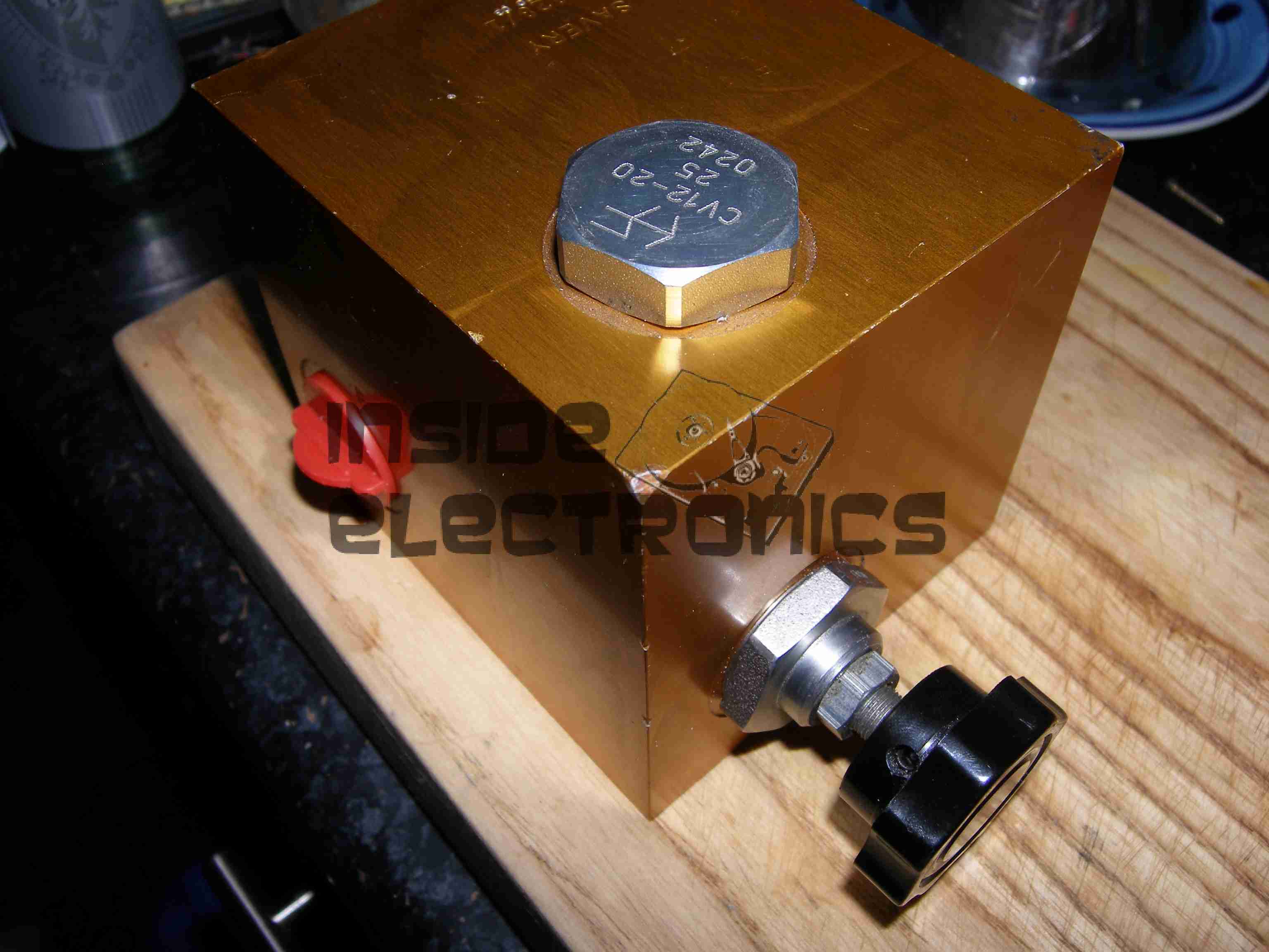
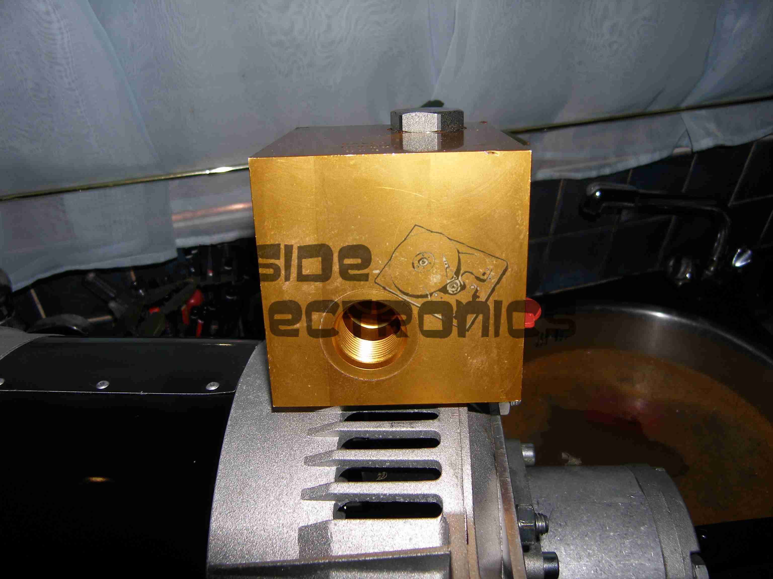
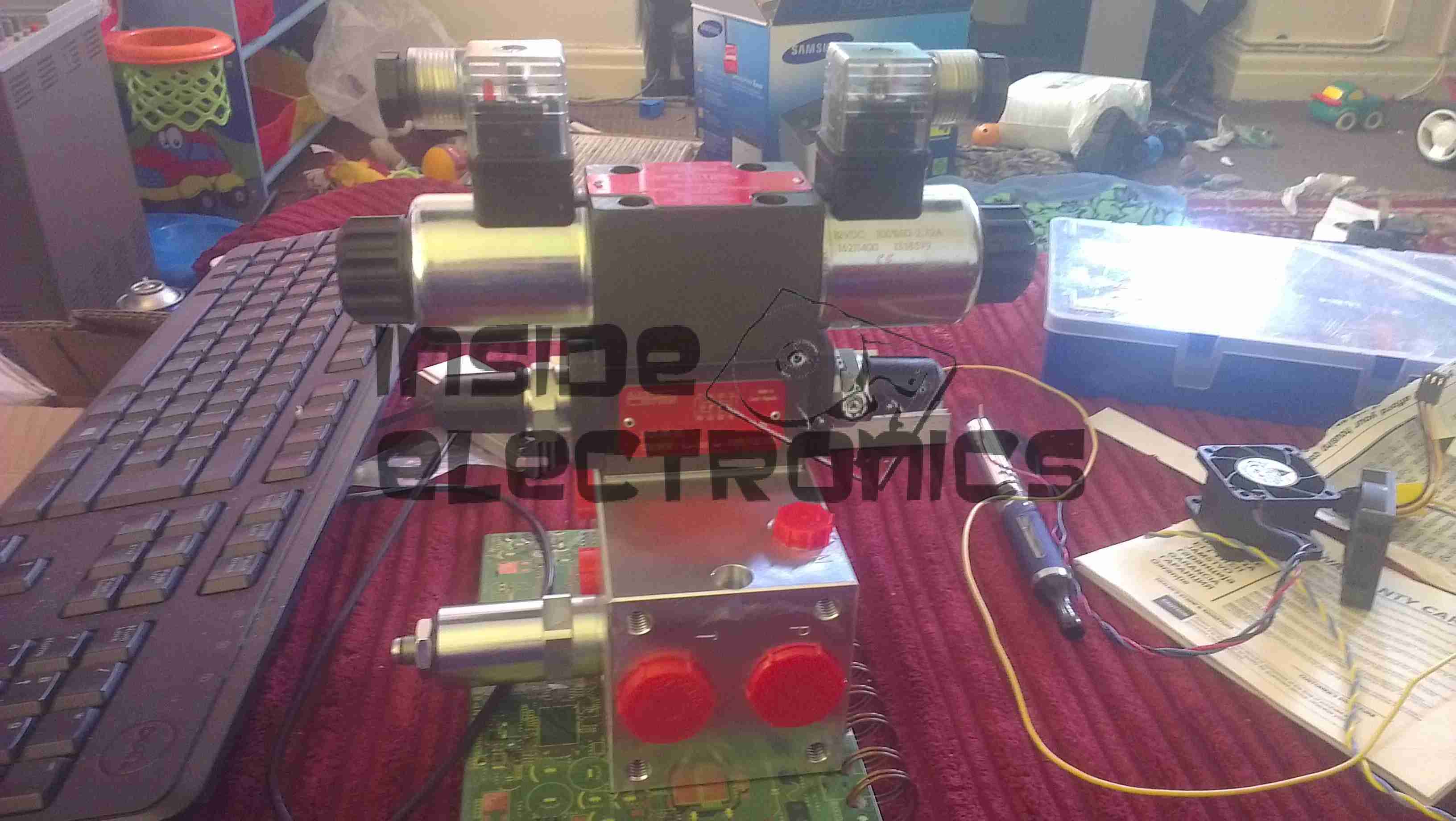
Finally, after months of messing about with the original seller of the generator unit, (Mike Webb from hydraulicgenerators.co.uk, more to come about the nightmare I had dealing with this man), we have had to purchase a new hydraulic control valve for the genset, as the original unit supplied was missing parts.
Thanks to Martin Bullock from BSP Hydraulics for supplying this at short notice!
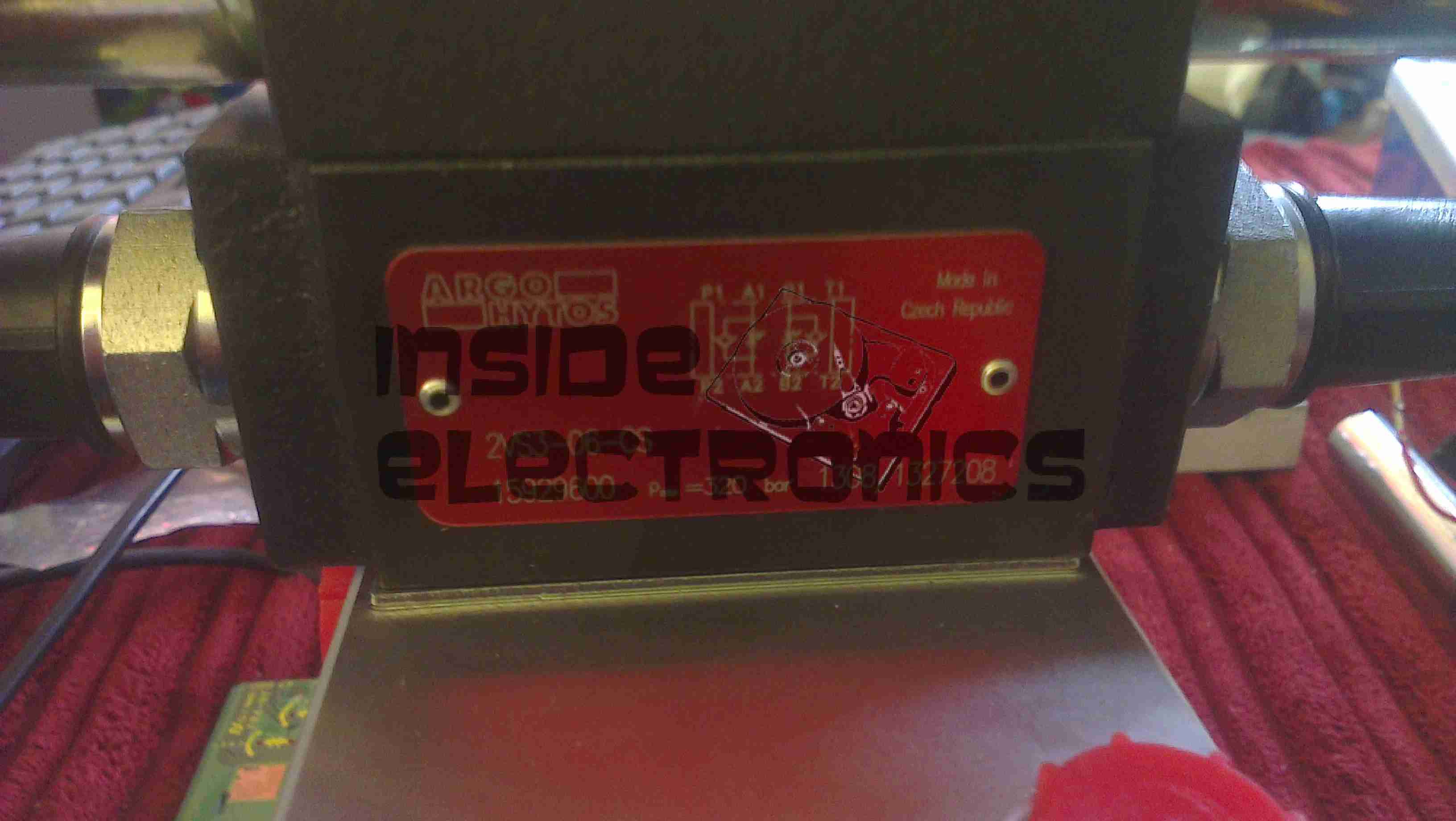
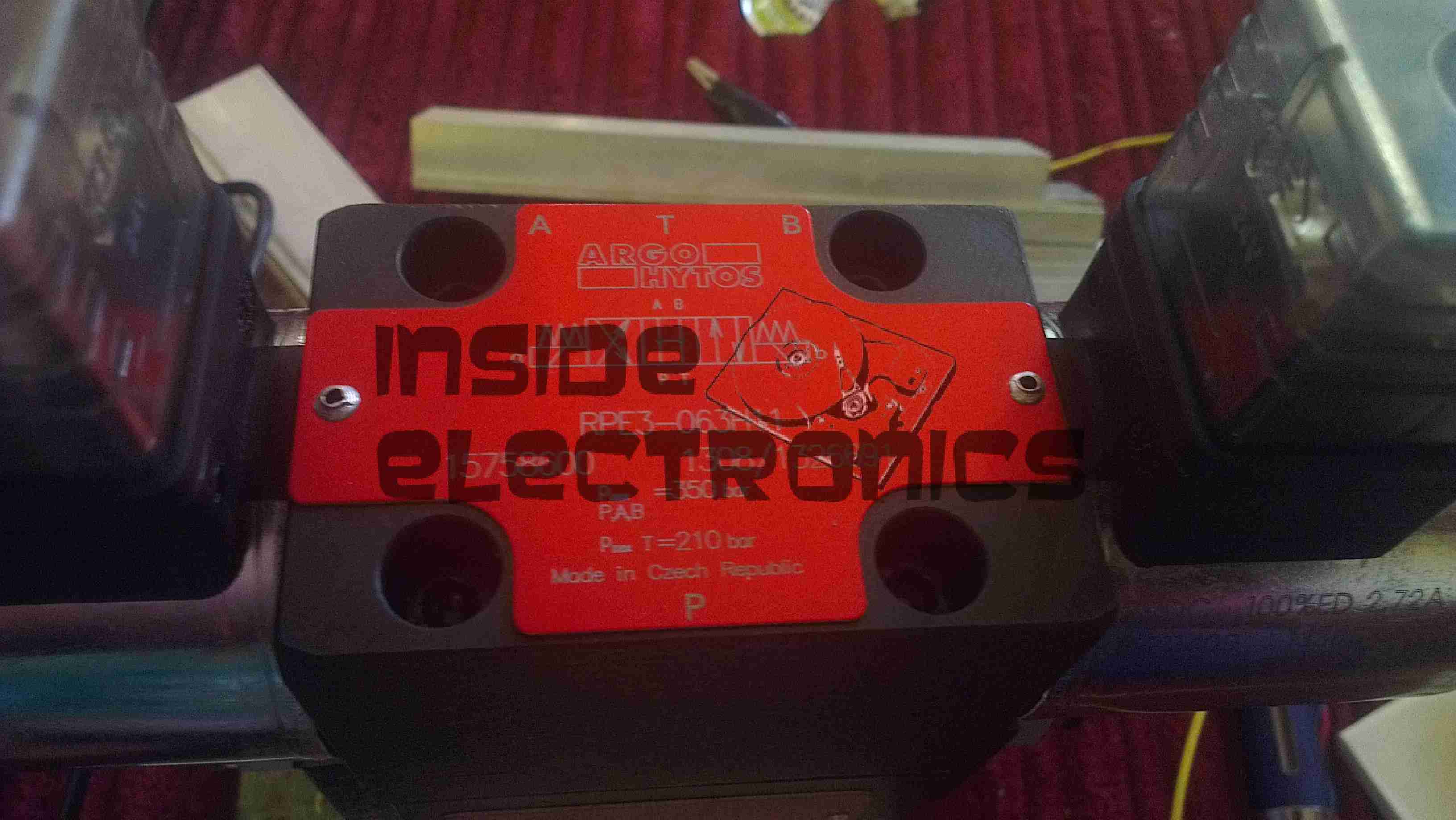
Flow Control ModuleSolenoid Spool ValveControl Valve Block
This unit contains a pressure relief valve, to set system operating pressure, a throttle/flow control valve to set generator motor speed & a solenoid controlled spool valve to control general oil flow to the generator. This last section effectively operates as an ON/OFF control.
System pressure will be ~175 Bar at 21 litres/minute.
More to come soon with the final assembly, hosing up & system commissioning.
Tip Jar
If you’ve found my content useful, please consider leaving a donation by clicking the Tip Jar below!
All collected funds go towards new content & the costs of keeping the server online.