Posted on Leave a comment

eBay Airbrush & Compressor

For my latest project, I needed an easier way to paint without messing about with brushes, and the associated marks they leave in a paint job. eBay provided me with a cheap airbrush & compressor.

Airbrush Kit
Airbrush Kit

For less than £30, this kit doens’t look so bad. I’ve never used an airbrush before, but I’ve had no problems with this as yet spraying both water based paints & solvent based paints.

Compressor
Compressor

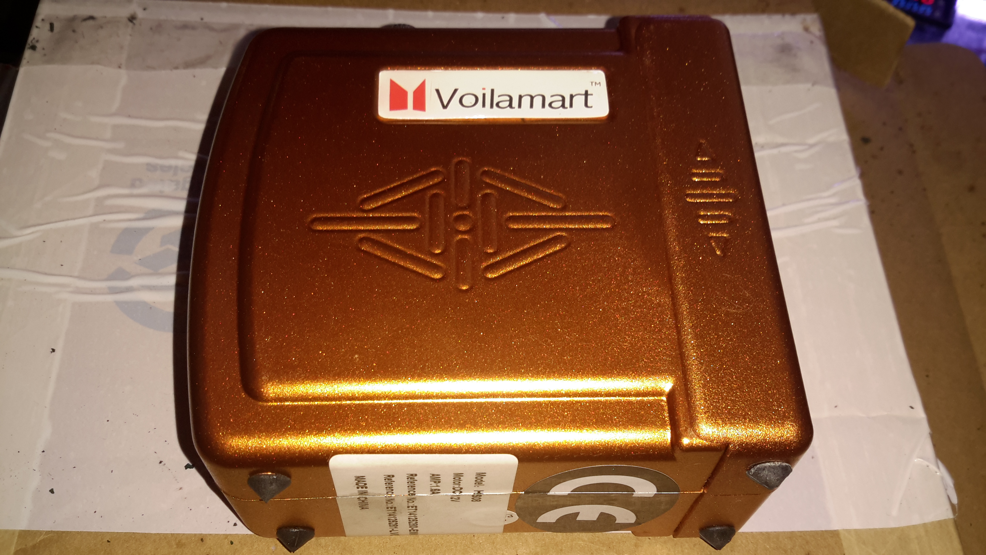
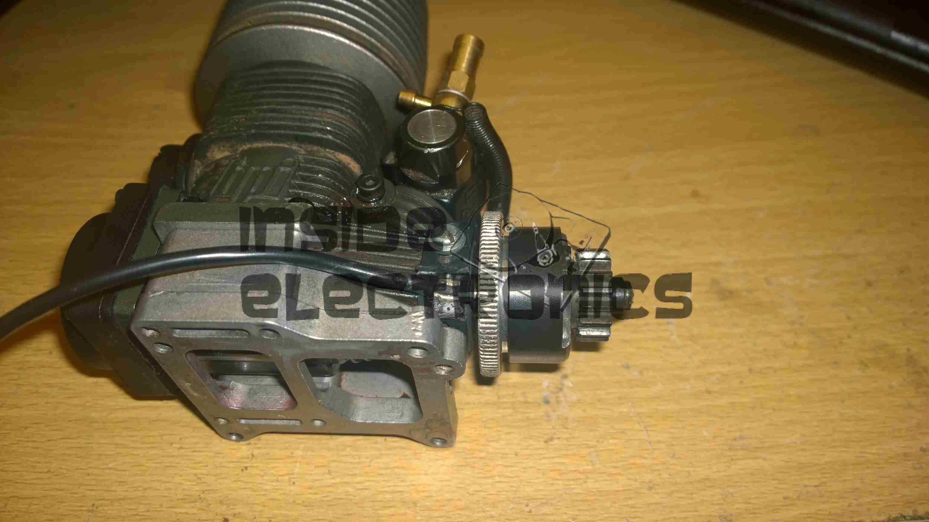
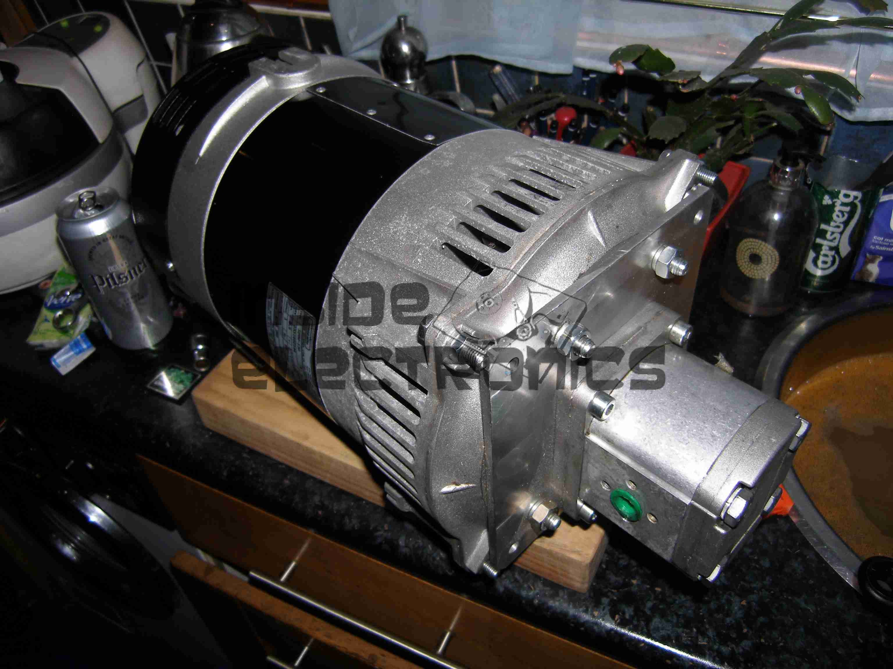
Here’s the compressor itself, this runs on 12v & has an output pressure of 1.5 Bar, which is supposed to be adjustable.

Compressor Internals

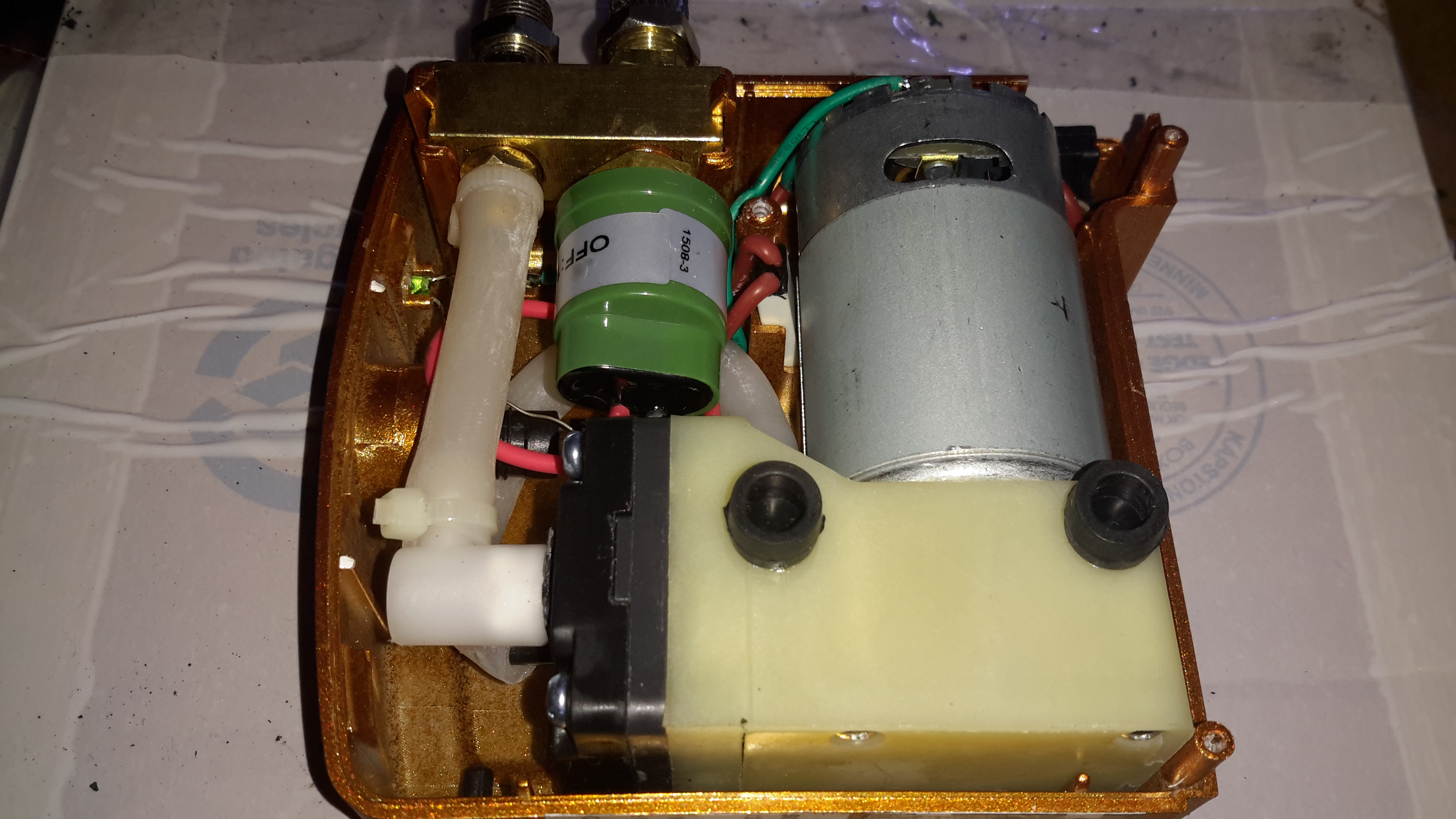
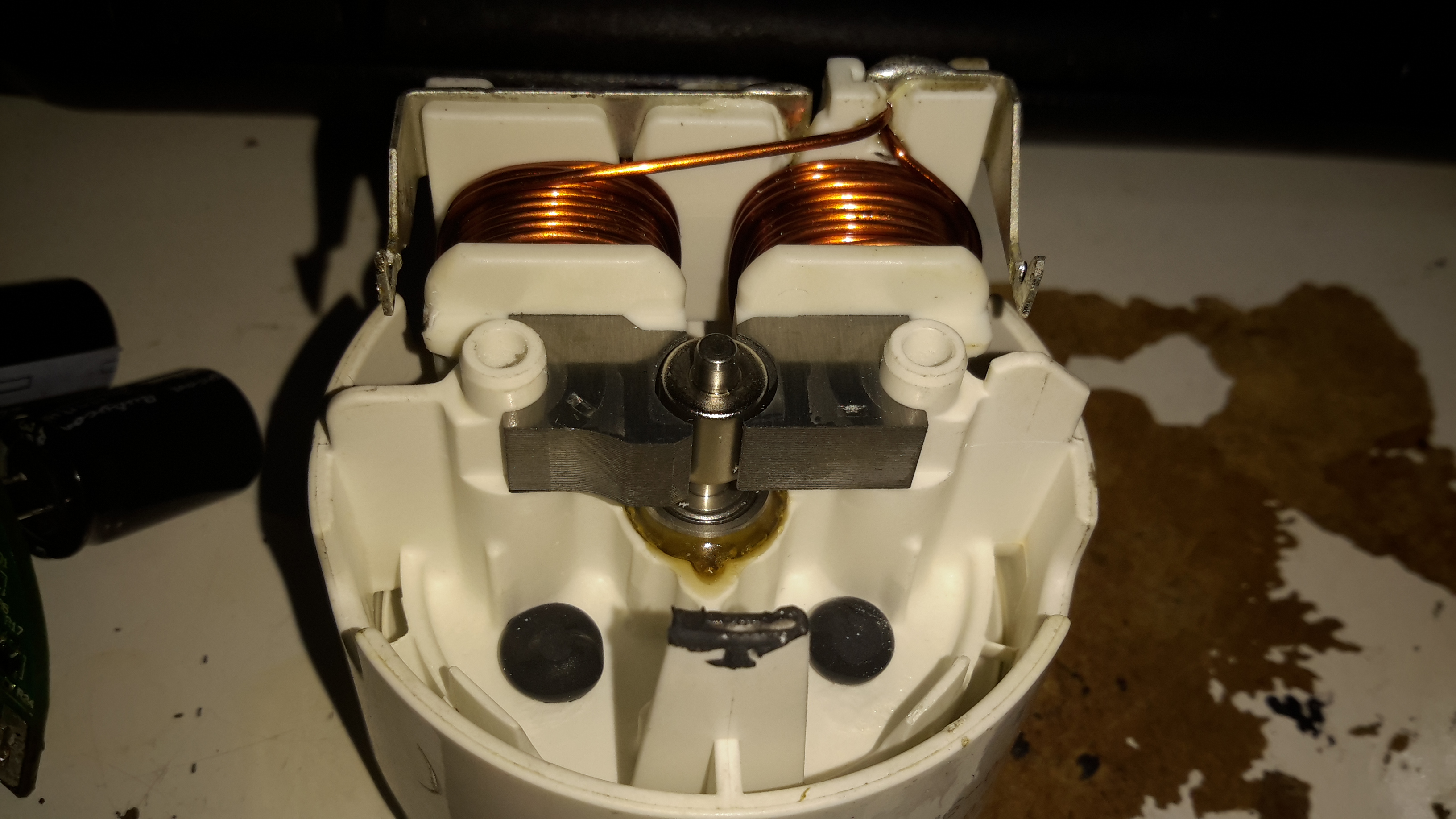
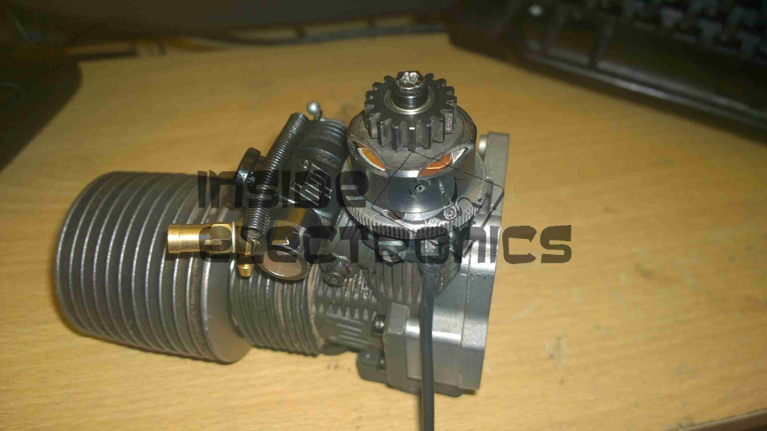
Removing a couple of screws reveals the internal components. Nothing much unusual here, a DC diaphragm pump, pressure switch & outlet fittings. There’s also a thermal cutout fitted next to the motor for protection.
The pressure switch attached to the manifold trips at 1.5Bar, keeping the pressure to the brush pretty much constant.

Air Block
Air Block

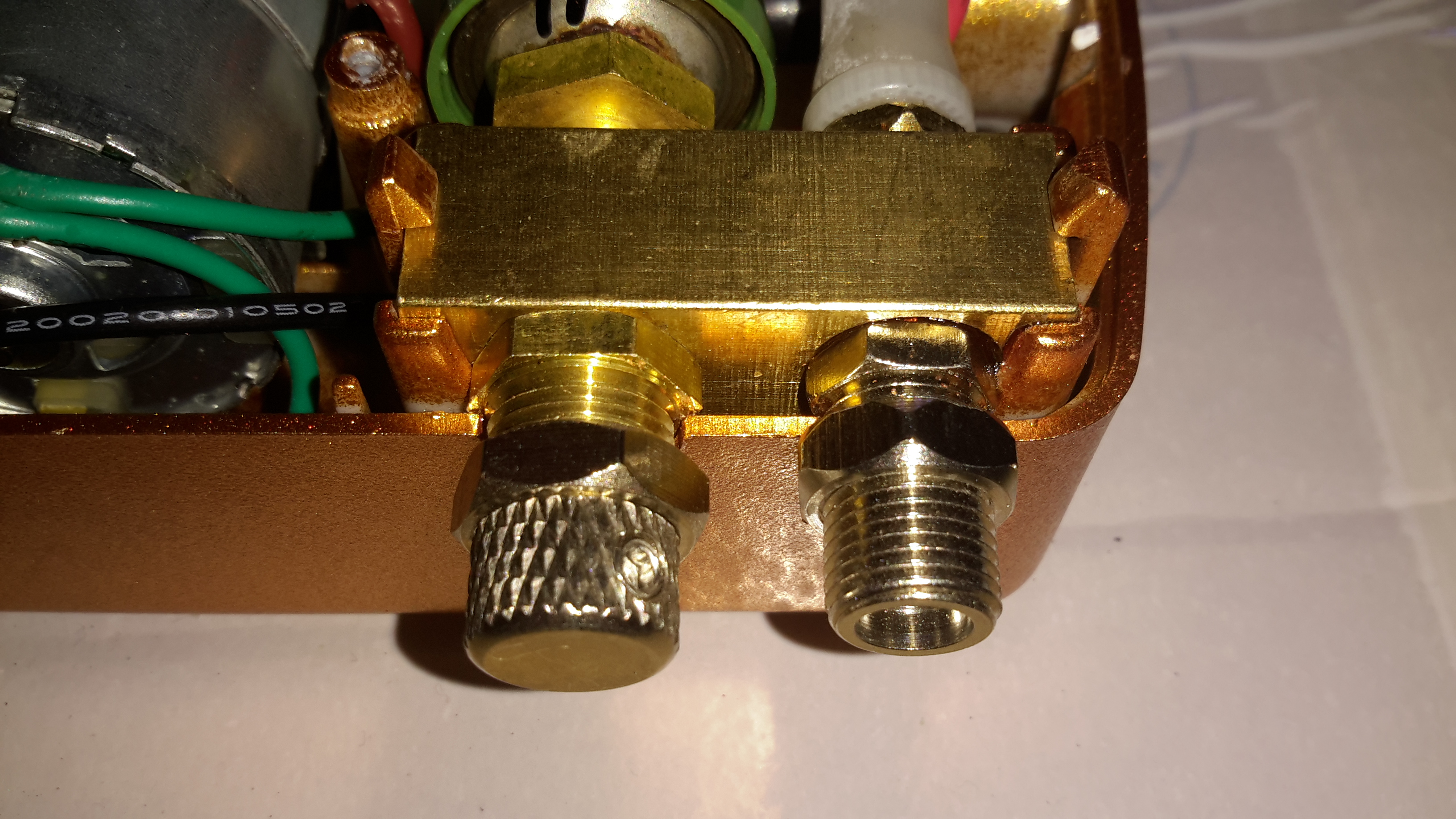
Next to the air outlet fitting is an adjustment knob, supposedly for varying the pressure. However it’s just a piss-poorly designed adjustable relief valve that vents to atmosphere. There’s not much of a control range.

Messy Wiring
Messy Wiring

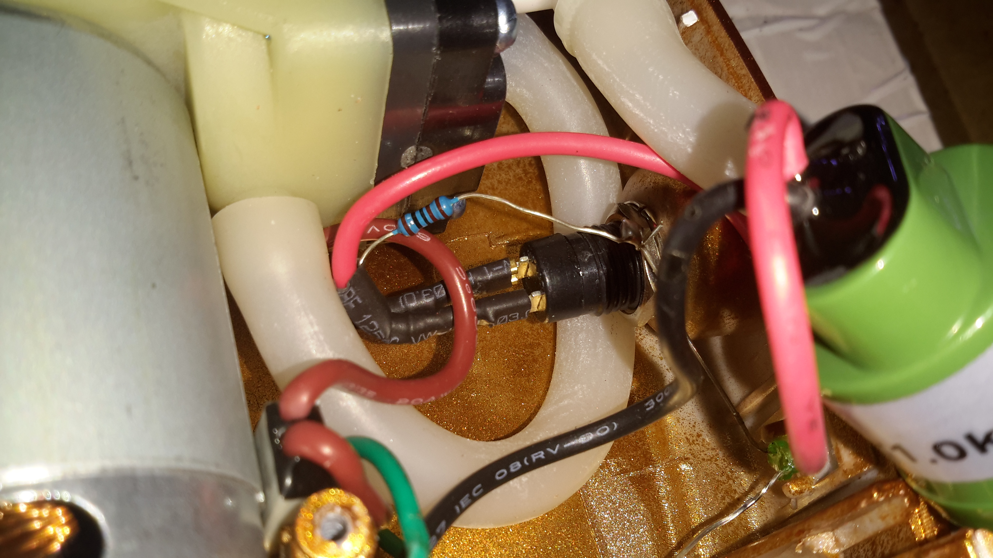
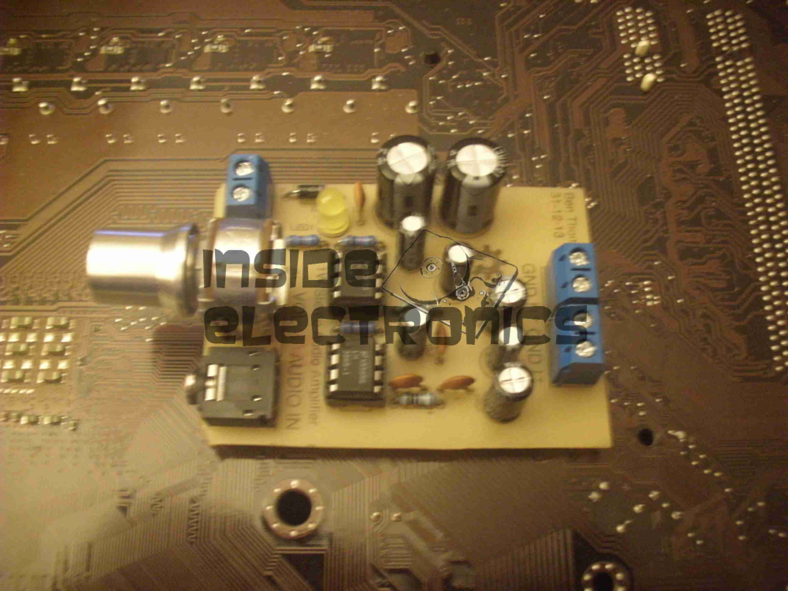
The wiring gets a bit messy where the power LED is concerned, with no heatshrink over the solder joints, but it’s adequate.

Airbrush
Airbrush

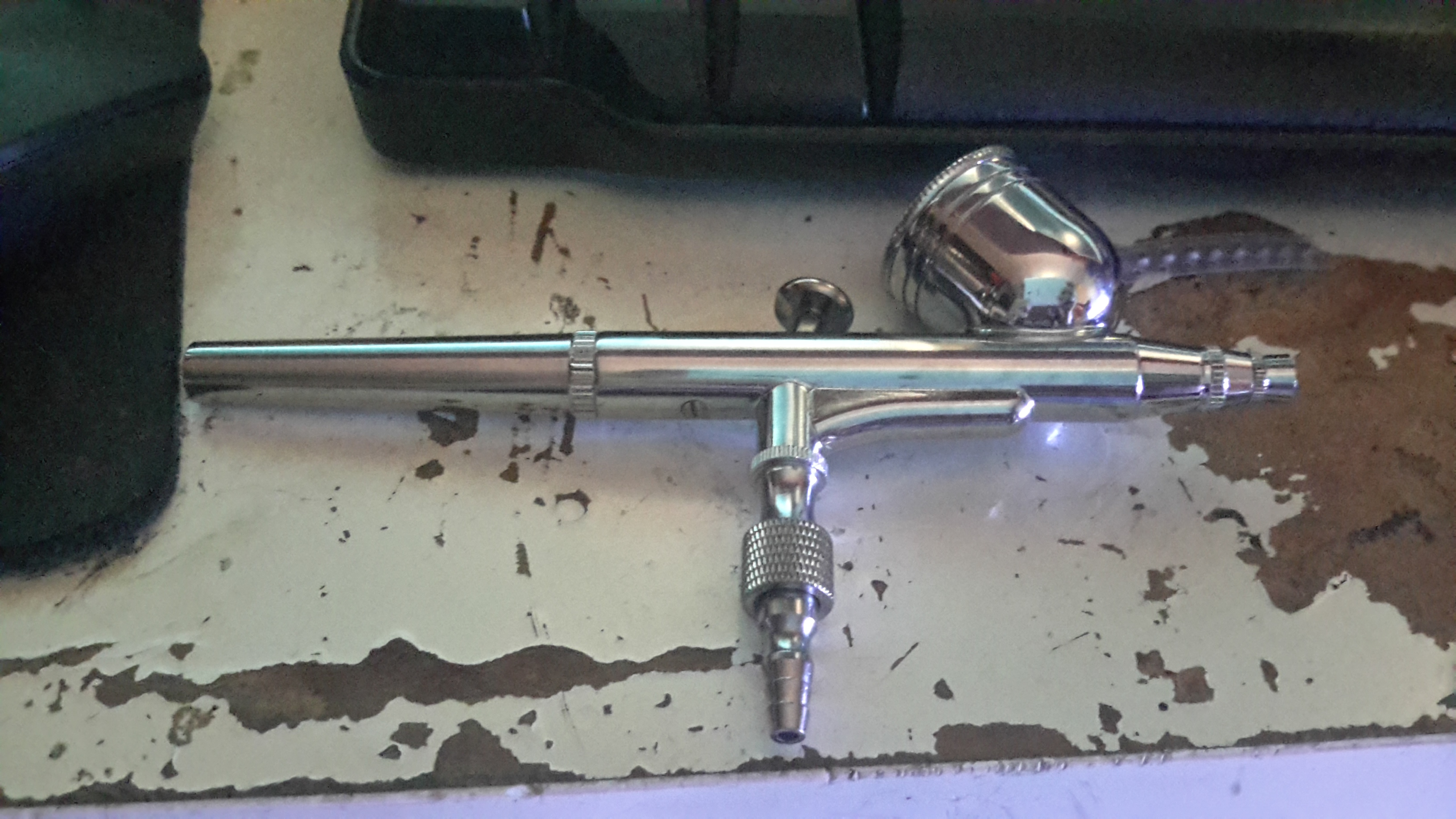
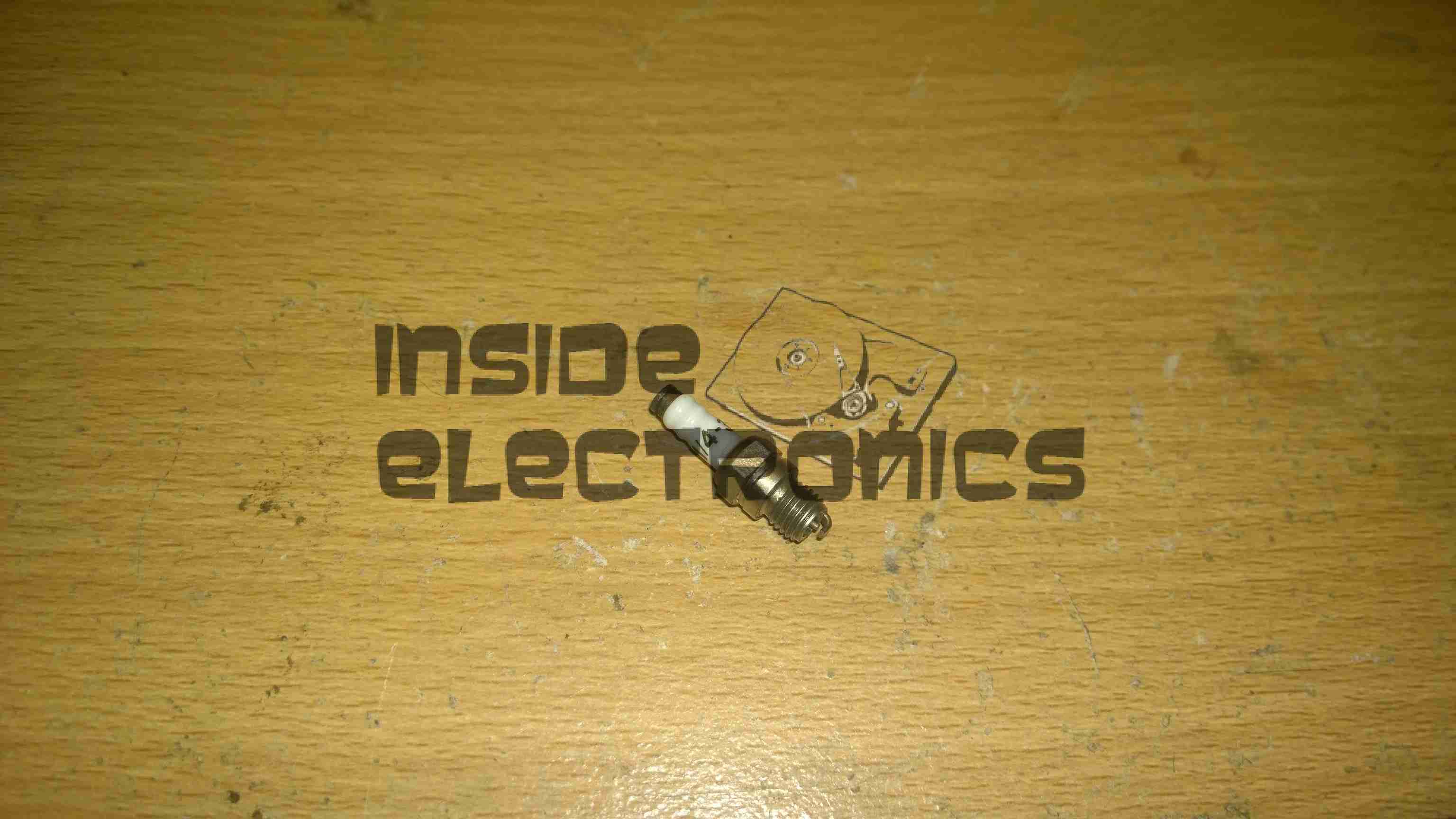
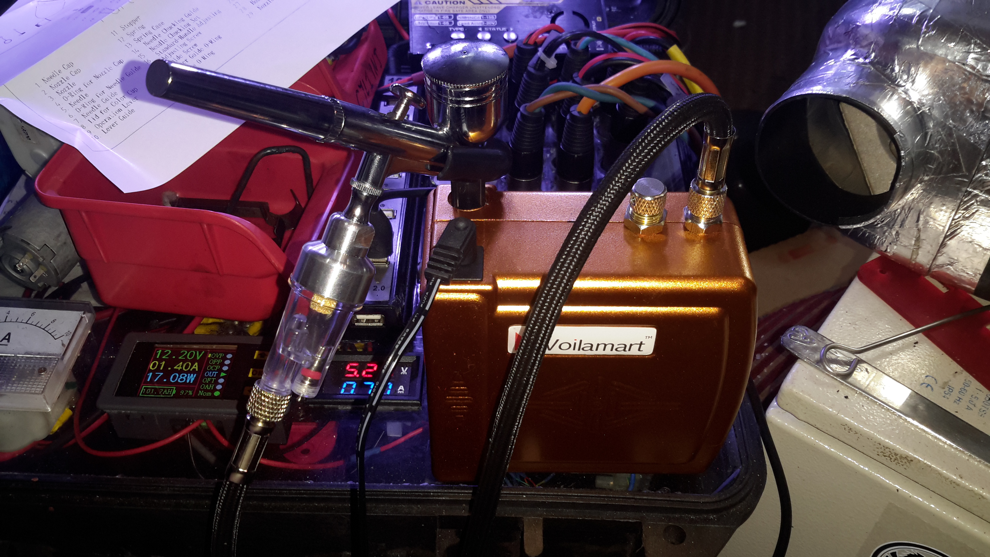
The airbrush itself isn’t too bad. It’s solid Brass, with a very nice Chrome finish. I’m not expecting miracles from a very cheap tool, but it certainly seems to be reasonable.

Water Trap
Water Trap

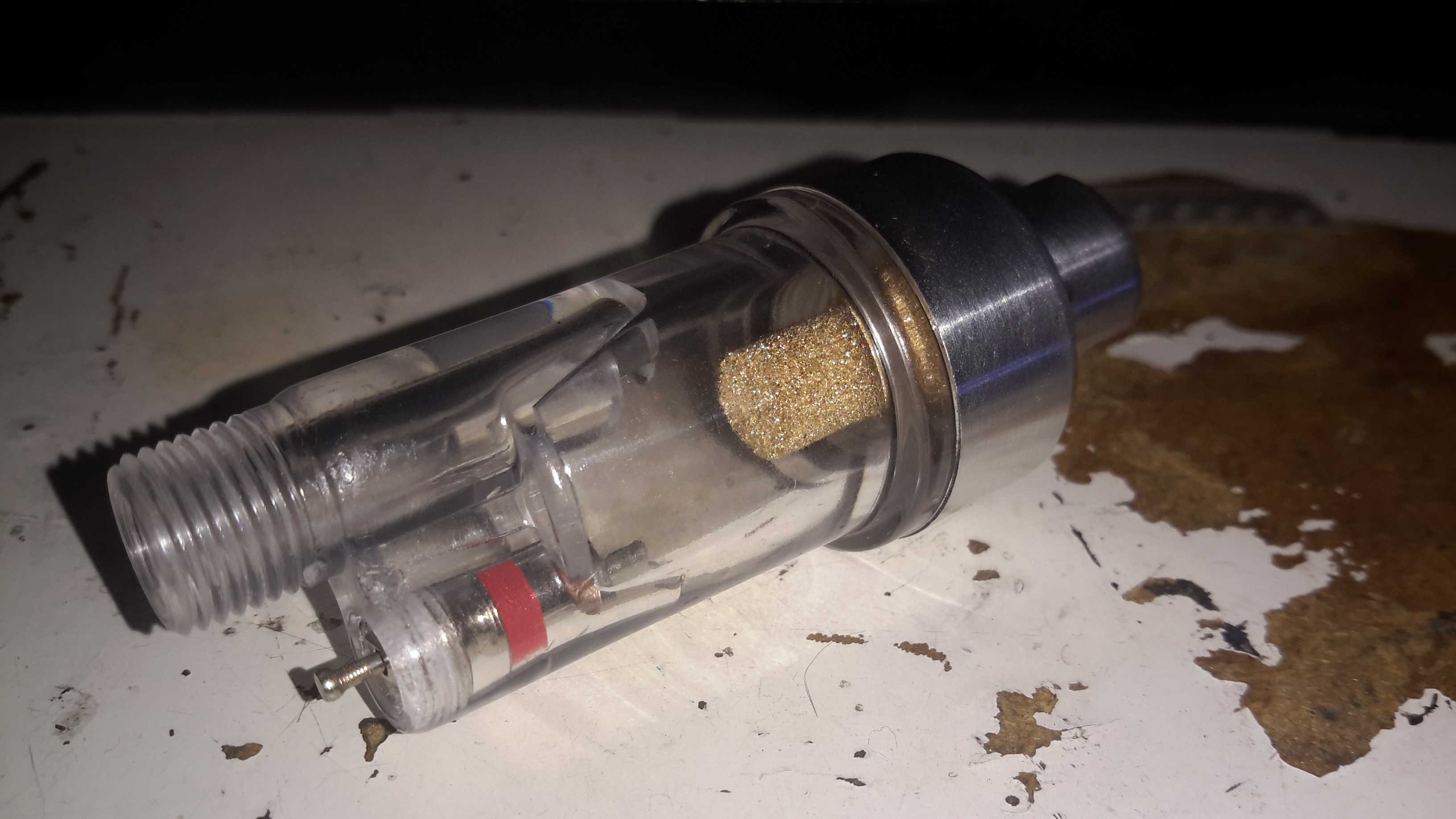
A moisture trap is supplied for the brush, to prevent water drops being sprayed out with the paint. Very handy.

Posted on 69 Comments

Dyson DC35 “Digital” Teardown

DC35
DC35

Here’s another Dyson teardown, in my efforts to understand how marketing have got hold of relatively simple technology & managed to charge extortionate amounts of money for it.
This is the DC35, the model after the introduction of the brushless digital motor.

Back Cap Removed
Back Cap Removed

On this version the mouldings have been changed, and the back cover comes off, after removing the battery retaining screw. It’s attached with some fairly vicious clips, so some force is required. Once the cap is removed, all the electronics are visible. On the left is the motor itself, with it’s control & drive PCB. There’s another PCB on the trigger, with even more electronics. The battery connector is on the right.

Trigger PCB
Trigger PCB

Here’s the trigger PCB, which appears to deal with DC-DC conversion for powering the brush attachments. The QFN IC with yellow paint on it is an Atmel ATTiny461 8-bit microcontroller. This is probably controlling the DC-DC & might also be doing some battery authentication.

"Digital Motor"
“Digital Motor”

Here’s the motor & it’s board. The windings on the stator are extremely heavy, which makes sense considering it’s rated at 200W. The main control IC is a PIC16F690 from Microchip. Instead of using an off the shelf controller, this no doubt contains software for generating the waveforms that drive the brushless motor. It also appears to communicate with the other PCBs for battery authentication.

Stator
Stator

Desoldering the board allows it to be removed from the motor itself. The pair of windings are connected in anti-phase, to create alternating North-South poles depending on polarity. Since the existing controller is unusable due to software authentication with the other parts, I might have a go at building my own driver circuit for this with an Arduino or similar.

Blower Assembly
Blower Assembly

The blower assembly is simple plastic mouldings, pressed together then solvent welded at the seam.

Impeller
Impeller

The impeller is just a centrifugal compressor wheel, identical to what’s used in engine turbochargers.

Motor Control Board
Motor Control Board

The inside face of the control PCB holds the 4 very large MOSFETs, IRFH7932PbF from International Rectifier. These are rated at 30v 20A a piece, and are probably wired in a H-Bridge. There’s a bipolar Hall switch to sense rotor position & rotation speed, and an enormous pair of capacitors on the main power bus.

Motor Control Board Reverse

Not much on the other side of the PCB other than the microcontroller and associated gate drive stuff for the FETs.

Battery Pack Opened
Battery Pack Opened

The battery pack is similar to the DC16 in it’s construction, a heavily clipped together plastic casing holding 6 lithium cells. In this one though there’s a full battery management system. The IC on the top of the board above is a quad Op-Amp, probably for measuring cell voltages.

Battery BMS Bottom
Battery BMS Bottom

The other side of the BMS board is packed with components. I wasn’t able to identify the QFN IC here, as it’s got a custom part number, but it’s most definitely communicating with the main motor MCU via I²C over the two small terminals on the battery connector.

Posted on Leave a comment

Mini Teardown: Eberspacher 701 BT Controller

It’s well known that there are two versions of the 701 type controller available for Eberspacher heaters, the version with the blue logo is the official un-restricted model, while the version with the white logo is a version built for BT that restricts the heater to 1 hour runtime & has no diagnostics built in.
As these devices are microcontroller driven, I assumed that the hardware would be the same, only the code running in the micro being the bit that Eberspacher changed. This option would certainly have been the lowest cost.

Controller PCB Rear
Controller PCB Rear

Here’s the PCB removed from the plastic housing. There are definitely some differences that I can tell. As the un-restricted version has an extra wire for the diagnostic serial interface, and this board has no unpopulated parts, the PCB is definitely a different version.
In the centre is a Microchip PIC16C622 microcontroller, the OTP version in this case for cost reductions. (I may try reading the binary from this chip in the future, chances are it’s code protected though).
Below the micro is an NXP PCF8577C 32-segment LCD controller, this has an I²C interface to the PIC.
The temperature control function on these heaters is done via applying a resistance to one of the control lines, between 1750Ω-2180Ω, ±80Ω. (Very odd values these, not to mention no standard components can create this range easily, bloody engineers >_<). This is accomplished in hardware with a BU2092F I²C shift register from Rohm, which is connected to a bank of resistors. The microcontroller will switch combinations of these into the circuit to get the range of resistances required.
The rest of the circuit is local power regulation & filtering.

Controller PCB Front

There’s not much on the other side of the PCB, just the LCD itself & the contacts for the buttons.

Posted on Leave a comment

Netgear GS308 Gigabit Switch

Here’s a new addition to the network, mainly to replace the ancient Cisco Catalyst 3500 XL 100MB switch I’ve been using for many years, until I can find a decently priced second hand commercial gigabit switch.

Operational
Operational

Here’s the switch with some network connections on test. So far it’s very stable & draws minimum power. I’ve not yet attempted to run my core links (NAS) through yet, as I’ve not yet seen a consumer grade switch that can stand up to constant full load without crashing.

Internals
Internals

Here’s the switch with it’s lid popped. The magnetics can be seen at the back, next to the RJ-45 ports, the large IC in the centre is the main switching IC, with a heatsink bonded to the top. Very minimal design, with only a couple of switching regulators for power supply & not much else.

Power & EEPROM
Power & EEPROM

Here’s a closeup of some of the support components. There’s a 25MHz crystal providing a clock signal for the switch IC, just to the right of that is an EEPROM. I imagine this is storing the switch configuration & MAC address. Further right is one of the switching DC-DC converter ICs for power.

As a quick test, here’s 500GB of data being shifted through the switch, at quite an impressive rate. I’m clearly maxing out the bandwidth of the link here. Soon I will upgrade to a 10G Ethernet link between the NAS & main PC to get some more performance.

Test
Test
Posted on 3 Comments

Evolis Dualys3 Card Printer Teardown

I recently dug out my other card printer to fit it with a 12v regulator, (it’s 24v at the moment), and figured I’d do a teardown post while I had the thing in bits.

This is a less industrial unit than my Zebra P330i, but unlike the Zebra, it has automatic duplexing, it doesn’t have Ethernet connectivity though.

Unlike domestic printers, which are built down to a price, these machines are very much built up to a spec, and feature some very high quality components.

Naked Printer
Naked Printer

Here’s the mechanism with the cowling removed. This is the main drive side of the printer, with the main drive stepper at left, ribbon take-up spool motor lower right, and the duplex module stepper motors at far right.

Main Motor Drive
Main Motor Drive

The main drive motor runs the various rollers in the card path through a pair of synchronous belts, shown here.

Main Stepper
Main Stepper

The stepper itself is a quality ball-bearing Sanyo Denki bipolar motor.

Main Stepper Driver
Main Stepper Driver

Electrical drive is provided to the stepper with a L6258EX DMOS universal motor driver. This chip can also drive DC motors as well as steppers.

Ribbon Supply Spool
Ribbon Supply Spool

Here is the encoder geared onto the ribbon supply spool. This is used to monitor the speed the ribbon is moving relative to the card.

Printer Top
Printer Top

Here’s a top view through the printer, the blue roller on the left cleans the card as it’s pulled from the feeder, the gold coloured spool to it’s right is the ribbon supply reel. The cooling fan on the right serves to stop the print head overheating during heavy use.

Spool Take Up Motor
Spool Take Up Motor

The spool take-up reel is powered by another very high quality motor, a Buhler DC gearmotor. These printers are very heavily over engineered!
This motor drives the spool through an O-Ring belt, before the gear above. This allows the drive to slip in the event the ribbon jams, preventing it from breaking.

Duplex Unit Stepper Drivers

The pair of steppers that operate the duplexing unit are driven by a separate board, with a pair of L6219DS bipolar stepper driver ICs. There are also a couple of opto-sensors on this board for the output hopper.


Main Control PCB
Main Control PCB

All the mechanisms of the printer are controlled from this main PCB, which handles all logic & power supply functions. Sections on the board are unpopulated, these would be for the Ethernet interface, smart card programming & magstripe programming.

Main CPU
Main CPU

The brains of the operation is this ColdFire MCF5208CVM166 32-bit microprocessor. It features 16KB of RAM, 8KB of cache, DMA controller, 3 UARTs, SPI, 10/100M Ethernet and low power management. This is a fairly powerful processor, running at 166MHz.
It’s paired with an external 128Mbit SDRAM from Samsung, and a Spansion 8Mbit boot sector flash, for firmware storage.

USB Interface & Power Input

Here the USB interface IC is located. It’s a USBN9604 from Texas Instruments, this interfaces with the main CPU via serial.

Posted on 3 Comments

Arduino Based SWR/PWR Meter – The Board

I recently posted about a small analog SWR/Power meter I got from eBay, and figured it needed some improvement.

After some web searching I located a project by ON7EQ, an Arduino sketch to read SWR & RF power from any SWR bridge.
The Arduino code is on the original author’s page above, his copyright restrictions forbid me to reproduce it here.

I have also noticed a small glitch in the code when it is flashed to a blank arduino: The display will show scrambled characters as if it has crashed. However pushing the buttons a few times & rebooting the Arduino seems to fix this. I think it’s related to the EEPROM being blank on a new Arduino board.

I have run a board up in Eagle for testing, shown below is the layout:

SWR Meter SCH
SWR Meter SCH

The Schematic is the same as is given on ON7EQ’s site.
Update: ON7EQ has kindly let me know I’ve mixed up R6 & R7, so make sure they’re switched round when the board is built ;). Fitting the resistors the wrong way around may damage the µC with overvoltage.

SWR Meter PCB
SWR Meter PCB

Here’s the PCB layout. I’ve kept it as simple as possible with only a single link on the top side of the board.

PCB Top
PCB Top

Here’s the freshly completed PCB ready to rock. Arduino Pro mini sits in the center doing all the work.
The link over to A5 on the arduino can be seen here, this allows the code to detect the supply voltage, useful for battery operation.
On the right hand edge of the PCB are the pair of SMA connectors to interface with the SWR bridge. Some RF filtering is provided on the inputs.

PCB Bottom
PCB Bottom

Trackside view of the PCB. This was etched using my tweaked toner transfer method.

LCD Fitted
LCD Fitted

Here the board has it’s 16×2 LCD module.

Online
Online

Board powered & working. Here it’s set to the 70cm band. The pair of buttons on the bottom edge of the board change bands & operating modes.
As usual, the Eagle layout files are available below, along with the libraries I use.

[download id=”5585″]

[download id=”5573″]

More to come on this when some components arrive to interface this board with the SWR bridge in the eBay meter.

Posted on Leave a comment

HPI Nitrostar F4.6 Ignition Conversion

As there was no other online example of someone converting a glow/nitro car engine onto CDI ignition, I thought I would document the highlights here.
The engine is currently still running on glow fuel, but when the required fuel lines arrive I will be attempting the switch over to 2-Stroke petrol mix. This should definitely save on fuel costs.

The engine in this case is a HPI NitroStar F4.6 nitro engine, from a HPI Savage X monster truck.

F4.6 Engine
F4.6 Engine

Above is the converted engine with it’s timing sensor. As The installation of this was pretty much standard, a complete strip down of the engine was required to allow the drilling & tapping of the two M3x0.5 holes to mount the sensor bracket to. The front crankshaft bearing has to be drifted out of the crankcase for this to be possible.

Ignition Hall Sensor

Detail of the ignition hall sensor. The bracket has to be modified to allow the sensor to face the magnet in the flywheel. Unlike on an Aero engine, where the magnet would be on the outside edge of the prop driver hub, in this case the hole was drilled in the face of the flywheel near the edge & the magnet pressed in. The Hall sensor is glued to the modified bracket with the leads bent to position the smaller face towards the back of the flywheel.
The clearance from the magnet to sensor is approx. 4mm.

Flywheel Magnet
Flywheel Magnet

Detail of the magnet pressed into the flywheel. A 3.9mm hole was drilled from the back face, approx 2mm from the edge, & the magnet pressed into place with gentle taps from a mallet & drift, as I had no vice to hand.
Initial timing was a little fiddly due to the flywheel only being held on with a nut & tapered sleeve, so a timing mark can be made inside the rear of the crankcase, across the crank throw & case to mark the 28 degree BTDC point, the flywheel is then adjusted to make the ignition fire at this point, before carefully tightening the flywheel retaining nut to ensure no relative movement occurs.
The slots in the sensor bracket allow several degrees of movement to fine adjust the timing point once this rough location has been achieved.

1/4"-32 Spark Plug
1/4″-32 Spark Plug

Definitely the tiniest spark plug I’ve ever seen, about an inch long. Some trouble may be encountered with this on some engines – the electrodes stick out about 2mm further into the combustion chamber than a standard glow plug does. This causes the ground electrode to hit the top of the piston crown. (This happens on the HPI NitroStar 3.5 engine). The addition of another copper washer under the plug before tightening should cure this problem.

RcExl CDI Ignition Module

Ignition module. Due to the depth of the plug in the heatsink head on these engines, I will have to modify the plug cap to straighten it out, as it will not fit in this configuration.
However, ignition modules are available from HobbyKing with straight plug caps, this makes modification unnecessary

The ignition & components used on this system were obtained from JustEngines.

Posted on Leave a comment

LM386 Stereo Audio Amplifier

The quickest project from inception to working PCB yet:

From inception to a working PCB took only 4 hours!

LM386 Amplifier
LM386 Amplifier

This is a miniature stereo audio amplifier, 0.5W per channel, that can be run from any voltage between 4-12v DC.

As usual, all the Eagle project files are available for download below & kits/bare PCBs will be available for sale for those that cannot etch boards.

In Operation
In Operation

Here is the circuit driving a pair of 3W 8Ω speakers from a line level audio source. The gain of this circuit is set at 50 with the components specified.


Schematic
Schematic

As can be seen from the schematic, this is a pair of single LM386 ICs for each channel.

Gain can be set by altering R3 & R4

[download id=”5566″]

Buy Kits Here £9.50:
[wp_cart_button name=”LM386 Stereo Audio Amplifier Kit” price=”9.50″]

Buy bare PCBs here £5:
[wp_cart_button name=”LM386 Stereo Audio Amplifier PCB” price=”5″]

PCBs are etched on FR4 laminate with 8oz copper with top component silkscreen.

Posted on Leave a comment

nb Tanya Louise Hydraulic Generator

Hydraulic Generator Unit

To accompany the previous two posts about hydraulic generators & their components, here is the actual generator unit itself.

Rated at 8.5kVa 230v AC, this will providea mains supply while the narrowboat is away from her home mooring.

This unit will be attached to the side of the hull in the engine room on rubber vibration isolation mounts, behind the main hydraulic oil tank & is driven from the small gear pump attached to the back of the main propulsion hydraulic pump unit.
Operating pressure is 175 bar, 21L/m flow rate to achieve the 3,000RPM rotor speed for 50Hz mains frequency.

Generator Specifications
Posted on Leave a comment

DIY Valve Amplifier – Part 1 – Amplifier Section

Components
Components

Here are a few details of a valve amplifier I am building, using the valve related parts from a 1960’s reel to reel tape recorder.

This amplifier is based on an a Mullard ECL82 triode/pentode valve, with an EM84 magic eye tube for level indication.

Beginnings Of The Amplifier

Here the first components are being soldered to the tags on the valve holder, there are so few components that a PCB is not required, everything can be rats-nested onto the valve holders.

Progress
Progress

Progressing with the amplifier section componentry, all resistors are either 1/2W or 2W.

Valve Sockets Fitted

Here the valve holders have been fitted, along with the output transformer, DC smoothing capacitor & the filament wiring, into the top of the plastic housing. At this point all the components that complete the amplifier section are soldered to the bottom of the right hand valve holder.

Wiring
Wiring

Starting the wiring between the valves & the power supply components. The volume control pot is fitted between the valve holders.

Valves Test Fit
Valves Test Fit

The valves here are test fitted into their sockets, the aluminium can at the back is a triple 32uF 250v electrolytic capacitor for smoothing the B+ rail.

Amplifier Section First Test

First test of the amplifier, with the speaker from the 1960’s tape recorder from which the valves came from. the 200v DC B+ supply & the 6.3v AC filament supply is derived from the mains transformer in the background.

Magic Eye Tube Added

Here the magic eye tube has been fitted & is getting it’s initial tuning to the amplifier section. This requires selecting combinations of anode & grid resistors to set the gap between the bars while at no signal & picking a coupling RC network to give the desired response curve.

Final Test
Final Test

Here both valves are fitted & the unit is sitting on it’s case for final audio testing. the cathodes of the ECL82 can be clearly seen glowing dull red here.


In the final section, I will build a SMPS power supply into the unit to allow it to be powered from a single 12v DC power supply.

Posted on 5 Comments

Rare Veroboard Design Tools – Stripboard Magic

Stripboard Magic

Stripboard Magic is a Windows application for designing PCB layouts on stripboard (aka prototyping board, aka Veroboard). It was released by a British company called Ambyr which ceased trading a long time ago.

The interface is a quite primitive and a little strange but the program is functional even on Windows XP. It also works great under wine in Linux, at least with version 0.9.38 and above as this is all I have checked. It should probably work on older versions too. I haven’t tried it on Vista though.

It can be a handy program when called upon and I have successfully used it a few times when throwing together random small circuits. Due to the interface I would imagine it to be a bit clumsy for very large circuits. The biggest gripe I have with it is the inability to change the orientation of components on the board, so some circuits tend to be slightly larger than they need to be.

I downloaded a copy of Stripboard Magic 1.0 back in the 90’s and recently just found it lying about on my computer. As I would consider it to well and truly be abandonware and as it seems to be a little sought after by some hobbyists I have provided a link to download it below.

[download id=”5624″]

Here are some screenshots showing the schematic view (top) and board layout view (bottom):


Stripboard Designer

Another hard to find app these days is Stripboard Designer, mirrored here for people who wish to use it.

[download id=”5626″]

[download id=”5628″]

Posted on Leave a comment

Window Break Alarm

Front
Front

Cheap unbranded window break alarm. Here is the front of the unit, with the sounder at the top, Power/sensitivity switch at the right. Battery test button at the left.

Rear
Rear

Rear of the device, with the adhesive pad used to attach it to a window.

Internals
Internals

Front cover removed, showing the batteries, PCB & the sounder.

PCB
PCB

PCB removed from the casing, showing the remaining components.

Posted on Leave a comment

Chicom “500W” ATX PSU

Cover Removed
Cover Removed

Here is a cheapo 500W rated ATX PSU that has totally borked itself, probably due to the unit NOT actually being capable of 500W. All 3 of the switching transistors were shorted, causing the ensuing carnage:

AC Input
AC Input

Here is the AC input to the PCB. Note the vapourised element inside the input fuse on the left. There is no PFC/filtering built into this supply, being as cheap as it is links have been installed in place of the RFI chokes.

Input Side
Input Side

Main filter capacitors & bridge rectifier diodes. PCB shows signs of excessive heating.

Filter Caps Removed
Filter Caps Removed

Filter capacitors have been removed from the PCB here, showing some cooked components. Resistor & diode next to the heatsink are the in the biasing network for the main switching transistors.

Heatsinks Removed
Heatsinks Removed

Heatsink has been removed, note the remaining pin from one of the switching transistors still attached to the PCB & not the transistor 🙂

Transformers
Transformers

Output side of the PSU, with heatsink removed. Main transformer on  the right, transformers centre & left are the 5vSB  transformer & feedback transformer.

Output Side
Output Side

Output side of the unit, filter capacitors, choke & rectifier diodes are visible here attached to their heatsink.

Comparator
Comparator

Comparator IC that deals with regulation of the outputs & overvoltage protection.

Posted on Leave a comment

PSP Slim

Front
Front

Here is a PSP Slim that recently died.

Label
Label

For those that are interested, here is the ID label, this is a PSP-2003.

Front Removed
Front Removed

Here the front of the unit has been removed, showing the first internal components.

Screen Removed
Screen Removed

Here is the unit with the LCD removed, here the mainboard is partially visible.

Left Pad
Left Pad

Left pad unit removed from the PSP, with the left speaker & the memory stick slot cover.

Left Pad Rear
Left Pad Rear

Rear of the left pad assembly, showing the speaker.

Joypad
Joypad

Joypad removed from the casing. Resistive unit.

Output Jack
Output Jack

Headphone/data board removed from the casing. This also has TV-Out on the PSP-200x series.

Mainboard
Mainboard

Mainboard removed. Main CPU is at the top. Sockets around the bottom connect to the UMD drive & UMD Drive.

CPU & GPU
CPU & GPU

Closeup of the main chipset. CPU is the top IC.

Mainboard Rear
Mainboard Rear

Rear of the mainboard, Memory Stick socket on the right.

WiFi Chipset
WiFi Chipset

Closeup of the WiFi chipset & the charging power socket on the right.

Charging Chipset
Charging Chipset

Closeup of the bettery connector & the charge controller IC.

UMD Drive
UMD Drive

UMD Drive removed from the rear of the casing. This is a miniature DVD style drive, using a 635nm visible red laser.

UMD Drive Back
UMD Drive Back

Rear of the UMD drive, showing the laser sled & drive motors. Both the spindle motor & the sled motor are 3-phase brushless type. The laser diode/photodiode array is at the top of the laser sled.

Posted on Leave a comment

Motorised Valve

This is the internals of a motorised valve for central heating systems. Here the top is removed showing the motor & microswitch.

Left side of the valve, showing the gearing under the motor, & the valve body under the powerhead.

Right side of the valve, showing the sprung mechanism of the valve quadrant.

Here the motor has been removed from the powerhead, showing the microswitch & the sprung quadrant gear. This spring keeps the valve closed until the motor is energized. The motor remains energized to hold the valve open.

Here the valve body has been opened showing the internal components. The rubber valve rotates on the shaft, blocking the lower port of the valve when in operation.

The motor’s protective cap has been removed here showing the rotor. This is a synchronous motor, of a special type for use in motorised valves. As the windings need to be continuously energized to hold the valve open, it is designed not to burn out under this load. 240v AC 50Hz, 5RPM.

Posted on 1 Comment

Co-Op Bank Card Reader

Keypad
Keypad

This is a little security measure you get with Internet Banking with the Co-Op, generates codes to confirm your identity using your bank card. About the size of a pocket calculator, this is the keypad & screen.

Card Slot
Card Slot

The rear of the unit, the card slots into the top, manufactured by Gemalto Digital Security.

Card Contacts
Card Contacts

Outer back cover removed, showing the 8 contacts for the chip on the bank card, the 2 contacts below that switch on power when a card is inserted. Power comes from 2 lithium coin cells in the compartment on the lower left.

PCB Rear
PCB Rear

PCB removed from the casing, showing the internal components. Two large pads at top left are battery connections, while the only IC on the board is the main CPU, under the card connector. 6MHz oscillator & 32Khz crystal on board for processing & timekeeping. LCD screen connection at far right.

Keypad Contacts
Keypad Contacts

Reverse side of the PCB, with the keypad contacts. LCD on right, with programming interface pads at side of keypad.

Posted on Leave a comment

ICL Barcode Scanner

Top
Top

An ICL barcode scanner from the 80s is shown here. This is the top of the unit with cover on.

Cover Removed
Cover Removed

Plastic cover removed from the unit showing internal components. Main PSU on left, scan assembly in center. Laser PSU & Cooling fan on right. Laser tube at top.

Scan Motor
Scan Motor

Closeup of laser scan motor. This unit scans the laser beam rapidly across the glass plate to read the barcode.

Controller PCB
Controller PCB

View of the bottom of the unit, showing the controller PCB in the centre.

Scan Motor Driver
Scan Motor Driver

The 3-phase motor driver circuit for the scan motor. 15v DC powered.

Laser Unit
Laser Unit

This is the laser unit disconnected from the back of the scanner. HT PSU is on right hand side, beam emerges from optics on left.

Laser Unit Label
Laser Unit Label

This unit is date stamped 1987. The oldest laser unit i own.

Tube PSU
Tube PSU

Laser tube power supply. Input voltage: 24v DC. Output: 1.8kV 4mA.

Laser PSU Board
Laser PSU Board

Rear of HT PSU. Obviously the factory made a mistake or two 🙂

Laser Tube Mounting
Laser Tube Mounting

Top cover removed from the laser unit here shows the 1mW He-Ne tube. Manufactured by Aerotech.

Tube Label
AeroTech He-Ne Tube

Tube label. Manufactured July 1993. Model LT06XR.

Plasma
Plasma

Here the tube has been removed from it’s mount to show the bore down the centre while energized.

OC Mirror
OC Mirror

OC end of the tube shown here lasing.

Beam
Beam

Beam output from the optics on the laser unit.

Tube Optics
Tube Optics

Optics built into the laser unit. Simple turning mirror on adjustable mount & collimating lens assembly.

Scan Lines
Scan Lines

Kind of hard to see but the unit is running here & projecting the scan lines on the top glass.

Laser Tube Mounting
Laser Tube Mounting

Laser tube mounting. A combo of spring clips & hot glue hold this He-Ne tube in place