Posted on 1 Comment

Velleman MK179

Completed Kit
Completed Kit

This is the Velleman MK179 Proximity Card Reader, which is supplied in kit form. In the image above you can see the completed kit, the read coil is etched onto the black PCB on the left. Bringing a recognised card close to the coil operates the relay on the main PCB for a programmable amount of time.

Main PCB
Main PCB

Closeup of the main PCB, 12v DC input at top right. Left IC is an LM358 dual Op-Amp, the IC on the right is a PIC12F629 with Velleman’s custom firmware.
Logic power is supplied to the ICs & the oscillator from the LM7805 regulator at the top of the PCB. The relay is a standard 15A SPDT 12v coil relay, with the switch contacts broken out onto the screw terminals on the left.

Schematic Diagram
Schematic Diagram

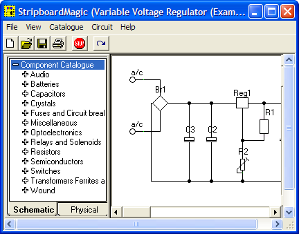
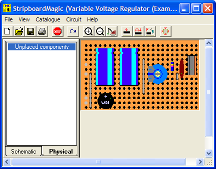
As it is not provided with the kit, unlike other Velleman kits, here is the schematic for this.


Posted on 1 Comment

MSR605 3-Track Magnetic Stripe Writer

MSR605
MSR605

This unit was bought from eBay to experiment with Magnetic Stripe cards, for little money. This unit is capable of reading & writing all 3 tracks, & both Hi-Co & Lo-Co card types.
Interfaced to a PC through USB, this has a built in PL2303 USB-Serial IC & requires 3A at 9v DC to operate.
The 3 Indicator LEDs on the top of the unit can be toggled by the included software for Power/OK/Fault condition signalling.

Unit Bottom
Unit Bottom

Bottom of the unit with the model labels.

Model Label
Model Label

Closeup of the model label & serial number.

PCB Bottom
PCB Bottom

Here the bottom cover has been removed, showing the main PCB. The pair of large ICs bottom center interface with the magnetic heads. The IC above them has had the markings sanded off.

USB-Serial Interface

Closeup of the Prolific PL-2303 USB-Serial converter IC.

PCB Top
PCB Top

Here the connections to the R/W heads are visible, current limiting resistors at the left for the write head, a pair of signal relays, a pair of optoisolators & a LM7805 linear voltage regulator.

LEDs
LEDs

Here is the trio of indicator LEDs on a small sub-board.

Frame Bottom
Frame Bottom

The PCB has been removed from the main frame here, the only component visible is the rotary encoder.

Rotary Encoder
Rotary Encoder

The rotary encoder has a rubber wheel fitted, which reads the speed of the card as it is being swiped for writing. This allows the control logic to write the data to the stripe at the correct rate for the speed of the card. This allows the unit to write cards from 5-50 inches per second speed.
The Write head is directly behind the rubber pressure roller.

Read/Write Heads
Read/Write Heads

Here you can see the R/W head assembly. The write head is on the right, read on the left. When a card is written to, it immediately gets read by the second head for verification.

The drivers for this unit are also available here: Magcard Writer Drivers

Posted on Leave a comment

Tool-less UK Mains Plug

Plug Bottom
Plug Bottom

This is a standard 13A UK main power plug – with a twist. This one requires no tools to open or connect.
The top cover is slid off the top, after turning the red cam with a coin to unlock it.

Plug Top
Plug Top

Manufactured by Plugco – a Google search of this company returns no results.

Cover Removed
Cover Removed

Top cover removed from the plug, as is standard with UK mains plugs the live conductor is fused – 3A in this case. The conductors are clamped into the fittings in a row along the top edge of the plug.

Wire Clamps
Wire Clamps

Closeup of the wire clamps. Conductor is placed in the slot & snapped closed.

This is an old plug & they do not appear to be available these days, for unknown reasons. Being able to change a plug without a screwdriver has it’s advantages 🙂

Posted on 5 Comments

Rare Veroboard Design Tools – Stripboard Magic

Stripboard Magic

Stripboard Magic is a Windows application for designing PCB layouts on stripboard (aka prototyping board, aka Veroboard). It was released by a British company called Ambyr which ceased trading a long time ago.

The interface is a quite primitive and a little strange but the program is functional even on Windows XP. It also works great under wine in Linux, at least with version 0.9.38 and above as this is all I have checked. It should probably work on older versions too. I haven’t tried it on Vista though.

It can be a handy program when called upon and I have successfully used it a few times when throwing together random small circuits. Due to the interface I would imagine it to be a bit clumsy for very large circuits. The biggest gripe I have with it is the inability to change the orientation of components on the board, so some circuits tend to be slightly larger than they need to be.

I downloaded a copy of Stripboard Magic 1.0 back in the 90’s and recently just found it lying about on my computer. As I would consider it to well and truly be abandonware and as it seems to be a little sought after by some hobbyists I have provided a link to download it below.

[download id=”5624″]

Here are some screenshots showing the schematic view (top) and board layout view (bottom):


Stripboard Designer

Another hard to find app these days is Stripboard Designer, mirrored here for people who wish to use it.

[download id=”5626″]

[download id=”5628″]

Posted on Leave a comment

Sigma Mini Keychain LCD Photoframe

Front
Front

This is a cheap Sigma branded keychain photoframe. User buttons for power & selecting photos are on the left.
There are two white LEDs on the bottom edge that function as a torch as well.

Display
Display

Front of the unit removed, showing the LCD module. The USB jack is bottom left, next to the pair of white LEDs & above that is the 32kHz watch crystal that the CPU uses for timekeeping.

Back Removed
Back Removed

Here the back has been removed showing the 3.7v Li-Ion cell used to provide power.

Display Folded Back
Display Folded Back

Here the display has been removed from the PCB exposing the chipset.

Chipset
Chipset

Here the CPU blob-top chip & a flash memory IC are visible. The CPU is a Sitronix ST2205U.

Posted on Leave a comment

PSi 150 Power Inverter

Front
Front

This is a small 120W power inverter, intended for small loads such as lights, fans, small TVs & laptop computers.

End Cover
End Cover

End cover of the unit, 12v DC input cord at the top, power switch & indicator LEDs at the bottom.

Mains Output
Mains Output

Opposite end of the unit, with the standard 240v AC 50Hz Mains output socket.

Cover Removed
Cover Removed

Cover removed from the top of the unit. Main power transformer is visible in the centre here, MOSFET bank is under the steel clamp on the left, the aluminium case forms the heatsink.

PWM Controllers
PWM Controllers

On the right is a KA3525 switchmode PWM controller & on the left is a LM324N quad Op-Amp IC. The buzzer on the far left is for the low battery warning.

PCB Removed
PCB Removed

PCB removed from the casing, with the MOSFET bank on the right hand side. Two potentiometers in the centre of the board tweak the frequency of the switcher & the output voltage.


Posted on Leave a comment

BigBen DSi Inductive Charging Dock

Front
Front

Here is a Inductive charger designed for the Nintendo DSi. Cheap Chinese build, but it does work!

Overview
Overview

Top has been removed from the unit here. Most prominent in the centre is a solid steel bar, simply there to give the device some weight.
Pair of Tri-colour LEDs at the front indicates charging status.
Induction coil is on the left, with the controller & oscillator PCB at the top.

PCB Closeup
PCB Closeup

Closeup of the PCB, ICs have had their markings ground off.

Coil
Coil

Induction coil. This couples power into a coil built into a special battery, supplied with the base, to charge it when the DSi is placed on the dock.

Label
Label

Information Label on the base.

Power Input
Power Input

Standard DSi charger port, connects to the charger you get with the DSi. Power switch is on the right.

Posted on Leave a comment

Brother P-Touch 80 Label Maker

Touchpad
Touchpad

Here is a label maker, bought on offer at Maplin Electronics. Full Qwerty keyboard with 1 line dot matrix LCD display visible here. Power is 4 AAA cells or a 6v DC Adaptor.

Rear
Rear

Rear cover removed. Battery compartment is on the left hand side, space for the tape cartridge on the right. Ribbon cable leading to the thermal print head is on the far right, with rubber tape drive roller.

PCB
PCB

PCB under the top cover with the main CPU, a MN101C77CBM from Panasonic. This CPU features 48K Mask ROM & 3K of RAM. Max clock frequency is 20MHz. 32kHz clock crystal visible underneath a Rohm BA6220 Electronic speed controller IC.
This is used to drive the printer motor at a constant accurate speed, to feed the tape past the thermal head. Miniature potentiometer adjusts speed.
Ribbon cable at the bottom of the board connects to the print head, various wiring at the left connects to the battery & DC Jack.

Printer Drive
Printer Drive

Printer drive mechanism. Small DC motor drives the pinch roller though a gear train. DC Jack & reverse polarity protection diode is on the right.
This unit uses a centre negative DC jack, which is unusual.

Cartridge
Cartridge

Thermal tape cartridge, black text on white background.

Posted on Leave a comment

Belkin 2 Port KVM Switch

Main Body
Main Body

Here is an old type KVM switch, PS/2 & VGA interface.

Label
Label

Details Label

Top Removed
Top Removed

Top removed from the main body, the cables coming in from the bottom connect to the VGA, keyboard & mouse ports on the slave computers, the connectors at the top connect to the single monitor, keyboard & mouse.

PCB
PCB

PCB removed from the body. This is driven by a PIC16C57C-04 microcontroller.
The pair of LEDs indicate which computer is using the peripherals at any one time.

Posted on Leave a comment

USB Multi Card Reader

Card Reader
Card Reader

Here is a cheap USB 8-in-1 card reader. Power & Access LEDs are on top left.

PCB Top
PCB Top

Top of the PCB. The OTi IC is the interface IC to the USB port, part number is OTI002126. Card sockets on the top here are CF/Microdrive & Memory Stick.

PCB Bottom
PCB Bottom

Bottom of the PCB with the SD/MMC, Smart Media

Posted on Leave a comment

Cheap Ball Mouse

Mouse
Mouse

Cheap old style ball mouse. PS/2 interface.

Top Removed
Top Removed

Top removed from the mouse, the ball fits in the gap in the centre. The slotted discs are visible which contact the ball & move relative to the surface the mouse is on.

PCB
PCB

PCB removed from the shell. Pairs of IR LEDs & Phototransistors make rotary encoders with the slotted discs. The microswitches read the mouse buttons & wheel.
IC in the centre interfaces with the PC over a PS/2 connection.

Posted on Leave a comment

USB-IDE/SATA Adaptor

Front
Front

This is a device to use an IDE or SATA interface drive via a USB connection. Here is the front of the device, IDE interface at the bottom, 2.5″ form factor.

PCB Top
PCB Top

PCB removed from the casing. USB cable exits the top, 12v DC power jack to the left.
SATA interface below the DC Jack.
Molex connector below SATA is the power output for the drive in use. This unit has a built in 5v regulator.

PCB Bottom
PCB Bottom

Bottom of the PCB showing the interface IC.

Drive Adaptor
Drive Adaptor

Adaptor to plug into the 44-pin 2.5″ form factor IDE interface on the adaptor, converts to standard 40-pin 3.5″ IDE.

Power Cable
Power Cable

Power pigtail with standard Molex & SATA power plugs.

Posted on Leave a comment

Sanyo Talkbook VAS

Front
Front

Here is a Sanyo tape recorder, with built in voice activation. Takes standard audio cassettes.
Here visible is the speaker on the left, microphone is on the right of the tape window. The tape counter is at the top.

Back Removed
Back Removed

Back cover removed from the unit, showing the PCB & the connections. The IC is the controller/amplifier.

PCB
PCB

Top of the PCB, control switches, volume potentiometer & microphone/headphone sockets on the right. DC power jack top left. Switch bottom centre senses what mode the tape drive is in.

Tape Deck
Tape Deck

Rear of the tape deck, main drive motor is bottom right, driving the capstan through a drive belt. This drives the tape spools through a series of gears & clutches. Belt going to top left drives the tape counter.

Drive
Drive

Front of the tape drive. Read/write head is top centre. Blue head is bulk erase head used during recording.

Speaker
Speaker

Main speaker. 8Ω 0.25W.

Counter
Counter

Simple mechanical tape counter.

Posted on Leave a comment

Grand Hand View

Front
Front

This is an adaptor to convert computer VGA to composite & S-Video output for a normal TV.

Bottom
Bottom

Bottom of the unit with option select switch.

PCB Top
PCB Top

PCB removed from the casing, CPU in centre, buffer RAM on the right.

PCB Bottom
PCB Bottom

Reverse side with the VGA connections at the top & the S-Video/composite outputs on the bottom.

VGA
VGA

Inputs. USB connector provides power, pair of VGA connectors provides passthrough function.

S-Video & Composite
S-Video & Composite

Outputs. Standard S-Video on the left & composite video on the right.

Posted on Leave a comment

Kidde Smoke Alarm

Top
Top

Old type ionization smoke alarm. Top of the device with the test button & sounder.

Bottom
Bottom

Bottom of the device. Battery compartment in centre.

PCB
PCB

Internals of the smoke alarm. Main component visible is the Ionization chamber.

Sounder
Sounder

Piezo sounder on inside of the top.

Ionization Chamber
Ionization Chamber

Inside the Ionization Chamber. 1µCi Americium-241 alpha particle source in the centre.
The radiation passes through the chamber, between the pair of electrodes, ionizing the air & permitting a small current to pass between the electrodes.
Any smoke that enters the chamber absorbs the alpha particles, which reduces the ionization and interrupts this current, setting off the alarm.

Controller
Controller

Controller IC beneath the chamber.

Posted on Leave a comment

IDE Zip Drive

Top
Top

An old IDE interface Zip drive. This fits in a standard 3.5″ bay.

Cover Removed
Cover Removed

Top cover removed from the drive, IDE & power interfaces at the top, in centre is the eject solenoid assembly & the head assembly. Bottom is the spindle drive motor.

Head Assembly
Head Assembly

Head assembly with the top magnet removed. Voice coil is on the left, with the head preamp IC next to it. Head chips are on the end of the arm inside the parking sleeve on the right. Blue lever is the head lock.

Controller
Controller

Controller PCB removed from the casing.

Spindle Motor
Spindle Motor

Spindle motor. This is a 3-phase DC brushless type motor. Magnetic ring on the top engages with the hub of the Zip disk when insterted into the drive.

Magnets
Magnets

Magnets that interact with the voice coil on the head assembly.

Head Armature
Head Armature

Head armature assembly removed from the drive. The arm is supported by a pair of linear bearings & a stainless steel rod.

Posted on Leave a comment

Belling Microwave


Front
Front

Here is a cheap no frills microwave oven, which died after a few weeks of normal use.

Electronics Bay
Electronics Bay

Cover removed, showing the internals. Front of the microwave is on the left.

Timer
Timer

Closeup of the timer unit. Cheap & nasty.

Magnetron
Magnetron

Magnetron removed from the oven. Antenna is on the top,  cooling fins visible in the center. White conector at the bottom is the filament terminals.

Magnetron Chokes
Magnetron Chokes

Chokes on the magnetron’s filament connections. These prevent microwave energy from feeding back into the electronics bay through the connections.

Magnetron Assembly
Magnetron Assembly

Magnetron cooling fins, tube & magnets removed from the frame.

Magnetron Tube
Magnetron Tube

Bare magnetron tube.

Power Input Board
Power Input Board

This PCB does some rudimentary power conditioning, power resistors are in series with the live feed to the power trasformer, to prevent huge power up surge. When the transformer energizes the relay, which is in parallel with the resistors, switches them out a fraction of a second after, providing full power to the transformer.
Standard RFI choke & capacitor at the top of the board, with the input resistor.

Transformer
Transformer

Power transformer to supply the magnetron with high voltage.
Power output is ~2kV at ~0.5A. Pair of spade terminals are the low voltage filament winding.

Capacitor
Capacitor

HV Capacitor. This along with the diode form a voltage doubler, to provide the magnetron with ~4kV DC.

Diode
Diode

HV diode stack.

Fuse Element
Fuse Element

Internals of the HV fuse. Rated for ~0.75A at 5kV. The fuse element is barely visible attached to the end of the spring. Connects between the transformer & the capacitor.

Cooling Fan
Cooling Fan

Cooling fan for the magnetron. Drive is cheap shaded pole motor.

Fan Motor
Fan Motor

Fan motor. Basic 240v shaded pole induction type.

Posted on 1 Comment

Hauppauge WinTV USB

Front
Front

Here is one of the first USB tuners that was available from Hauppauge Computer Works. Totally analog tuner of course, this model required 2 cables – a USB interface & a sound cable for the audio output of the tuner.

I/O
I/O

A/V connections.

Label
Label

For those who are interested. Here is the label with the model details.

Antenna Connection
Antenna Connection

Connection to an external antenna.

PCB Bottom
PCB Bottom

Bottom of the PCB.

PCB Top
PCB Top

Top of the PCB showing the USB interface IC (top left), cache memory (top right) & the main tuner assembly.

Posted on Leave a comment

Hot Laminator

Top
Top

Here is a cheap no brand hot laminator. This pulls the paper, inside a plastic pouch through a pair of heated rollers to seal it.

Heater
Heater

Top removed, heater assembly visible. PCB attached to the top cover holds LEDs to indicate power & ready status.

Switch
Switch
Thermostat
Thermostat

Here is the thermostat & thermal fuse, the thermostat switching the indicator on the front panel to tell the user when the unit is up to temperature. This has a self regulating thermostat. Thermal fuse inside the heat resistant tubing is to protect against any failure of the heater.

Motor
Motor

5 RPM motor that turns the rollers through a simple gear system.

Posted on Leave a comment

Window Break Alarm

Front
Front

Cheap unbranded window break alarm. Here is the front of the unit, with the sounder at the top, Power/sensitivity switch at the right. Battery test button at the left.

Rear
Rear

Rear of the device, with the adhesive pad used to attach it to a window.

Internals
Internals

Front cover removed, showing the batteries, PCB & the sounder.

PCB
PCB

PCB removed from the casing, showing the remaining components.

Posted on Leave a comment

£1 Shop LED Glitter Lamp

LED Glitter Lamp
LED Glitter Lamp

This is a decorative lamp from the £1 shop. Inside are RGB LEDs.

Internals
Internals

Internals removed from the base of the unit. The 3 LEDs are visible on the top & the tilt activation switch on the edge of the PCB.

IC
IC

Side of the PCB with the RGB controller IC, which is under a blob of epoxy.

Battery Holder
Battery Holder

Reverse side of the PCB, showing the battery holder & the tilt switch. This runs on 3 button cells.

Posted on 4 Comments

Audi TT Roof Hydraulics

Pump
Pump

This is the hydraulic system from an Audi TT that would power the soft top. Here is the hydraulic pump unit. Oil Tank is on the left. Power is 12v DC at ~20A

Cylinders
Cylinders

The pair of hydraulic cylinders that attached to the roof mechanism.

Limit Switch
Limit Switch

One of the cylinders has a limit switch built in. The brass bolt coming out of the side of the head is one contact. The other contact is the cylinder body.

Hose
Hose

Marking on the hoses. This is Parker Polyflex hydraulic hose. 1/8″ ID.

Motor
Motor

Drive motor for the hydraulic pump. Standard DC permanent magnet motor.

Motor Suppression
Motor Suppression

Motor power terminals & suppression capacitors. As the reversing relays actually short the motor out when de-energized, there is a lot of arcing at the brushes without some suppression.

Reversing Relays
Reversing Relays

Reversing relay stack. Each relay is a SPDT configuration. The pair are arranged as a DPDT bank to reverse the motor, depending on which relay is energized.

Tank
Tank

Detail of the oil tank showing the level markings.

Power Valve
Power Valve

Solenoid valve on top of the unit. This valve provides full pump pressure to the cylinders when energized.

Posted on Leave a comment

Uniden Stalker Radar Detector

Top
Top

An early speed radar detector from the early 90’s. Pictures showing the front of the unit with the option buttons.

Bottom
Bottom

Bottom of the unit showing label. Unlike the newer plastic detectors, the whole casing of this unit is cast aluminium.
Model Uniden Stalker RD-6000W.

PCB Top
PCB Top

PCB removed from the casing. Volume/power control on the left. Option tactile switches on the edge of the PCB, with the indicator LEDs. Power input jack on the right hand side of the PCB. Large aluminium can is the detector assembly, containing the detector diodes. Waveguide horn is at the top.

Waveguide Horn
Waveguide Horn

Shot down the waveguide, showing the detector diodes at the end.

LEDs
LEDs

Indicators on the front of the unit, X, K & Ka band detection LEDs on the left, Power & detection level (1-4) LEDs in centre. City (C) (Audio (A) & Mute (M) LEDs on the right.

PCB Bottom
PCB Bottom

Bottom of the PCB, showing detection logic. Piezo buzzer top left.

CPU
CPU

Custom Uniden CPU. Marking UC1465.

Posted on Leave a comment

PSP Slim

Front
Front

Here is a PSP Slim that recently died.

Label
Label

For those that are interested, here is the ID label, this is a PSP-2003.

Front Removed
Front Removed

Here the front of the unit has been removed, showing the first internal components.

Screen Removed
Screen Removed

Here is the unit with the LCD removed, here the mainboard is partially visible.

Left Pad
Left Pad

Left pad unit removed from the PSP, with the left speaker & the memory stick slot cover.

Left Pad Rear
Left Pad Rear

Rear of the left pad assembly, showing the speaker.

Joypad
Joypad

Joypad removed from the casing. Resistive unit.

Output Jack
Output Jack

Headphone/data board removed from the casing. This also has TV-Out on the PSP-200x series.

Mainboard
Mainboard

Mainboard removed. Main CPU is at the top. Sockets around the bottom connect to the UMD drive & UMD Drive.

CPU & GPU
CPU & GPU

Closeup of the main chipset. CPU is the top IC.

Mainboard Rear
Mainboard Rear

Rear of the mainboard, Memory Stick socket on the right.

WiFi Chipset
WiFi Chipset

Closeup of the WiFi chipset & the charging power socket on the right.

Charging Chipset
Charging Chipset

Closeup of the bettery connector & the charge controller IC.

UMD Drive
UMD Drive

UMD Drive removed from the rear of the casing. This is a miniature DVD style drive, using a 635nm visible red laser.

UMD Drive Back
UMD Drive Back

Rear of the UMD drive, showing the laser sled & drive motors. Both the spindle motor & the sled motor are 3-phase brushless type. The laser diode/photodiode array is at the top of the laser sled.

Posted on Leave a comment

Logitech Cordless Ball Mouse

Top
Top

This is an old legacy wireless mouse from Logitech. This uses a ball rather than optical technology.

Bottom
Bottom

Bottom of the mouse, showing the battery cover & the mouse ball.

PCB Bottom
PCB Bottom

Top removed from the mouse, showing the PCB inside. The smaller PCB on the left supports the microswitches for the buttons & mouse wheel.

Switches
Switches

Closeup of small PCB showing the microswitches & the IR LED & phototransistor pair for the mouse wheel encoder.

Main PCB
Main PCB

View of main PCB, with interface IC lower right. Pair of quartz crystals provide clocking for the transmitter & internal µC.
Battery contacts are on lower left of the PCB. At the top are the IR pairs for the X & Y axis of the mouse ball.

Encoder Pairs
Encoder Pairs

Closeup of the pairs of IR LEDs & phototransistors that make up the encoders for X/Y movement of the mouse, together with the slotted wheels in the mouse base that rotate with the ball. Steel wire around the smaller PCB is the antenna.