In my previous post, I mentioned I’d be replacing the factory supplied charging gear with something that actually charges lithium chemistry cells correctly.
Charging Base
Here’s the base as supplied, with an indicator LED on the right hand side. This LED indicates nothing other than power being applied to the charging base. It’s just connected across the power input with a resistor. This also means that any battery left in the charger while it’s unplugged will discharge itself through this LED over time. Great design there China!
PCB Removed
Here I’ve removed the PCB – there’s no need for it to be taking up any space, as it’s just a complete waste of copper clad board in the first place. The battery tabs have been desoldered & hot snot used to secure them into the plastic casing.
USB Hole
The charger modules I use are USB powered, so a small hole has been routed out in the casing to allow access to the port.
Charging Module
Here the charging module has been installed & wired to the battery tabs. Output is now a nice 4.18v, and will automatically stop charging when the cell is full.
Safety has been restored!
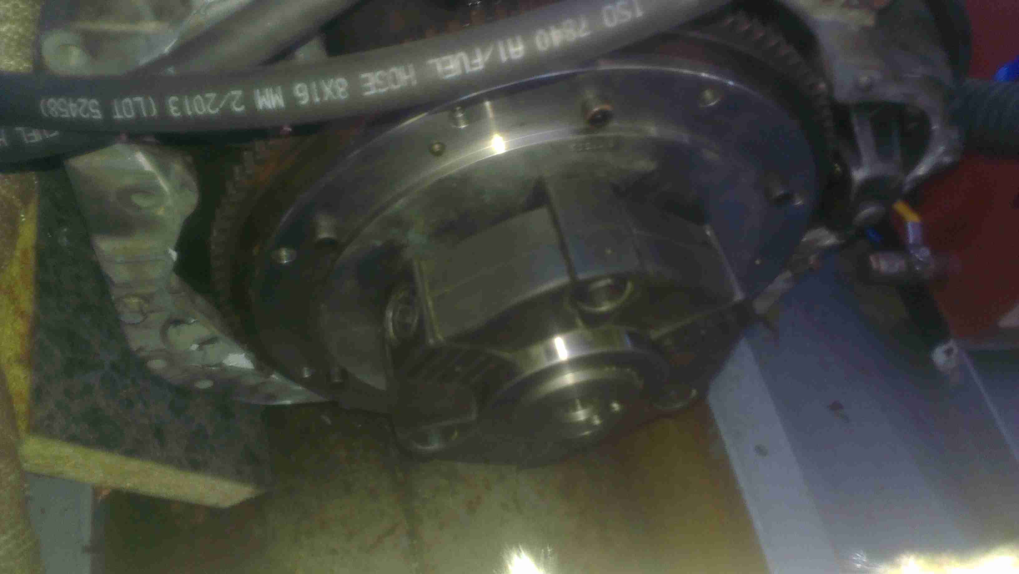
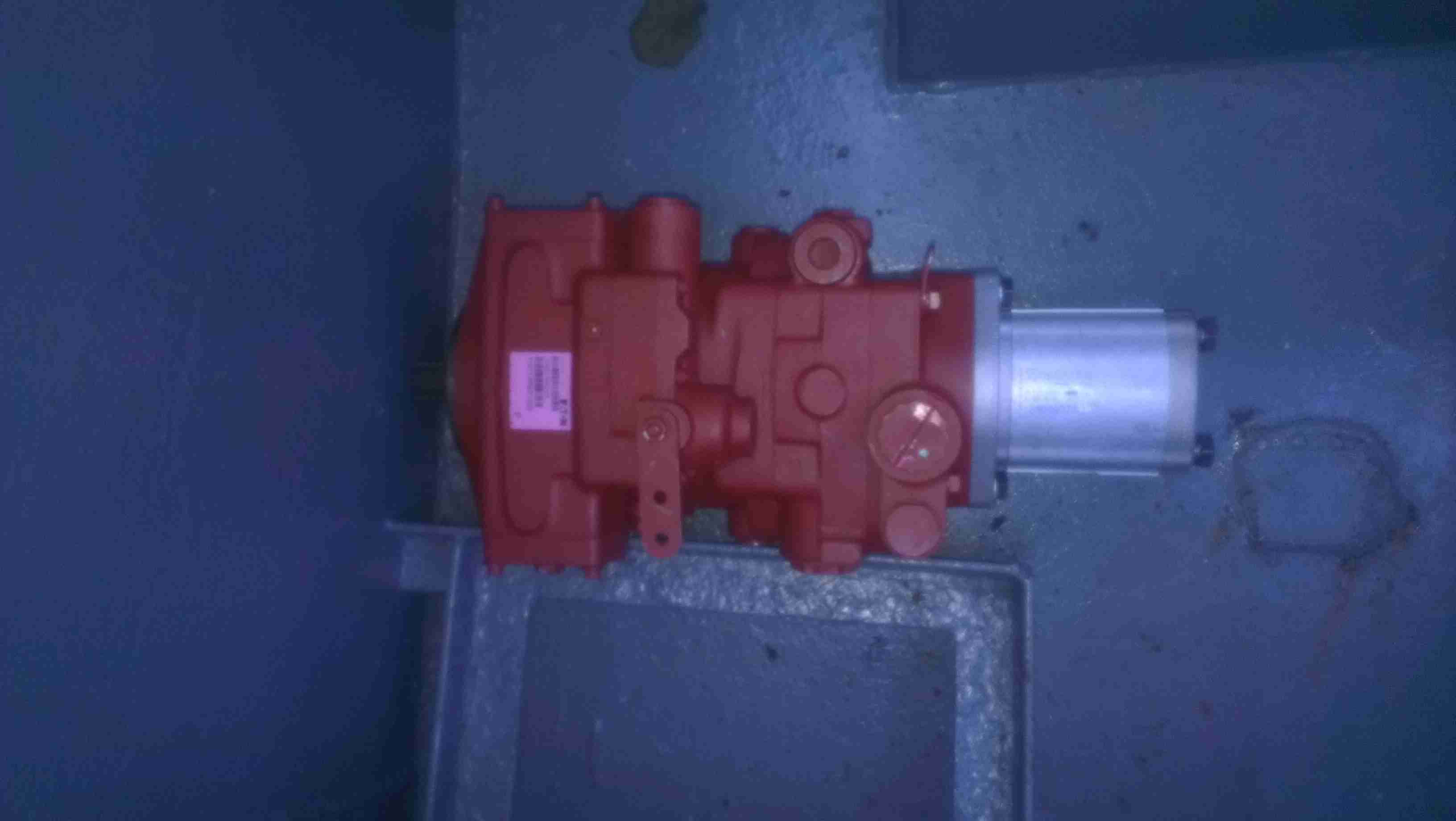
As I have posted about before, the main propulsion system onboard the boat is all hydraulic. To get the drive from the flywheel of the engine to the hydraulic pump stack, a custom drive plate was machined by Centa Transmissions over in Yorkshire, and a Centaflex A coupling was fitted to this.
Centaflex A Coupling
This coupling is a big rubber doughnut, bolted to a centre hub of steel. The steel hub is splined onto the input shaft of the hydraulic pump stack.
Pump Stack
The problem we’ve had is that to prevent the coupling from riding along the splines in operation, a pair of giant grub screws are provided in the side of the centre steel boss, that compress the splines to lock the device in place. These screws are a nightmare to get tightened down (the engineer from Centa who originally came to survey the system said we’d probably shear some tools off trying).
Because of this, the grub screws have loosened over the last 350-odd hours of running & this has had the effect of totally destroying the splines in the hub.
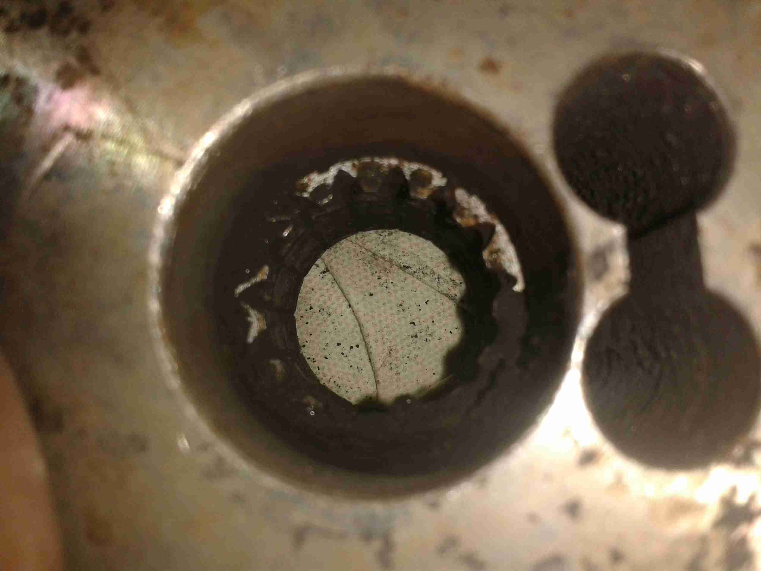
Spline Remains
Here’s the backside of the centre boss, with what remains of the splines, the figure-8 shaped gap on the right is where the securing grub screws deform the steel to lock the coupling into place.
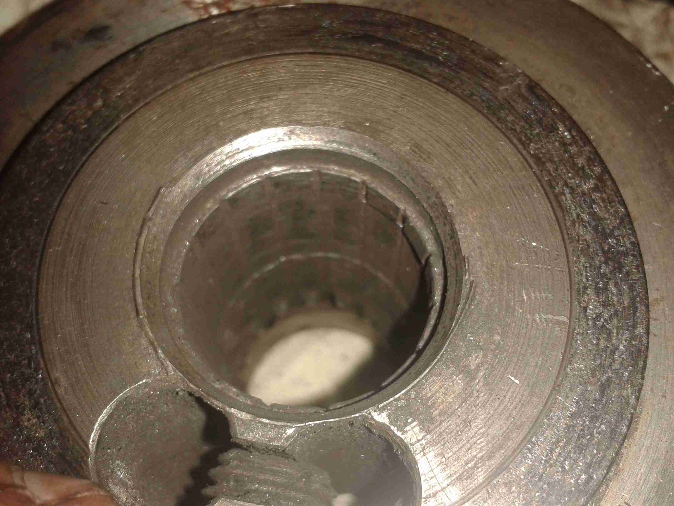
No More Splines
Here’s the other side of the coupling, showing the damage. The splines have effectively been totally removed, as if I’d gone in there with a boring bar on the lathe. Luckily this part isn’t too expensive to replace, and no damage was done to the input shaft of the hydraulic pump stack (Mega ££££). Quite luckily, this damage got to the point of failure while running the engine on the mooring, so it didn’t leave us stranded somewhere without motive power.
The power supplies I have recently built from surplus Cisco switch boards have started displaying a rather irritating problem – continual load of over 9A causes the supplies to shut down on overheat.
This was partially expected, as the original switches that these supplies came from are cooled by a monster of a centrifugal blower that could give a Dyson a run for it’s money. The problem with these fans is that they’re very loud, draw a lot of power (3-4A) and aren’t small enough to fit into the case I’ve used for the project.
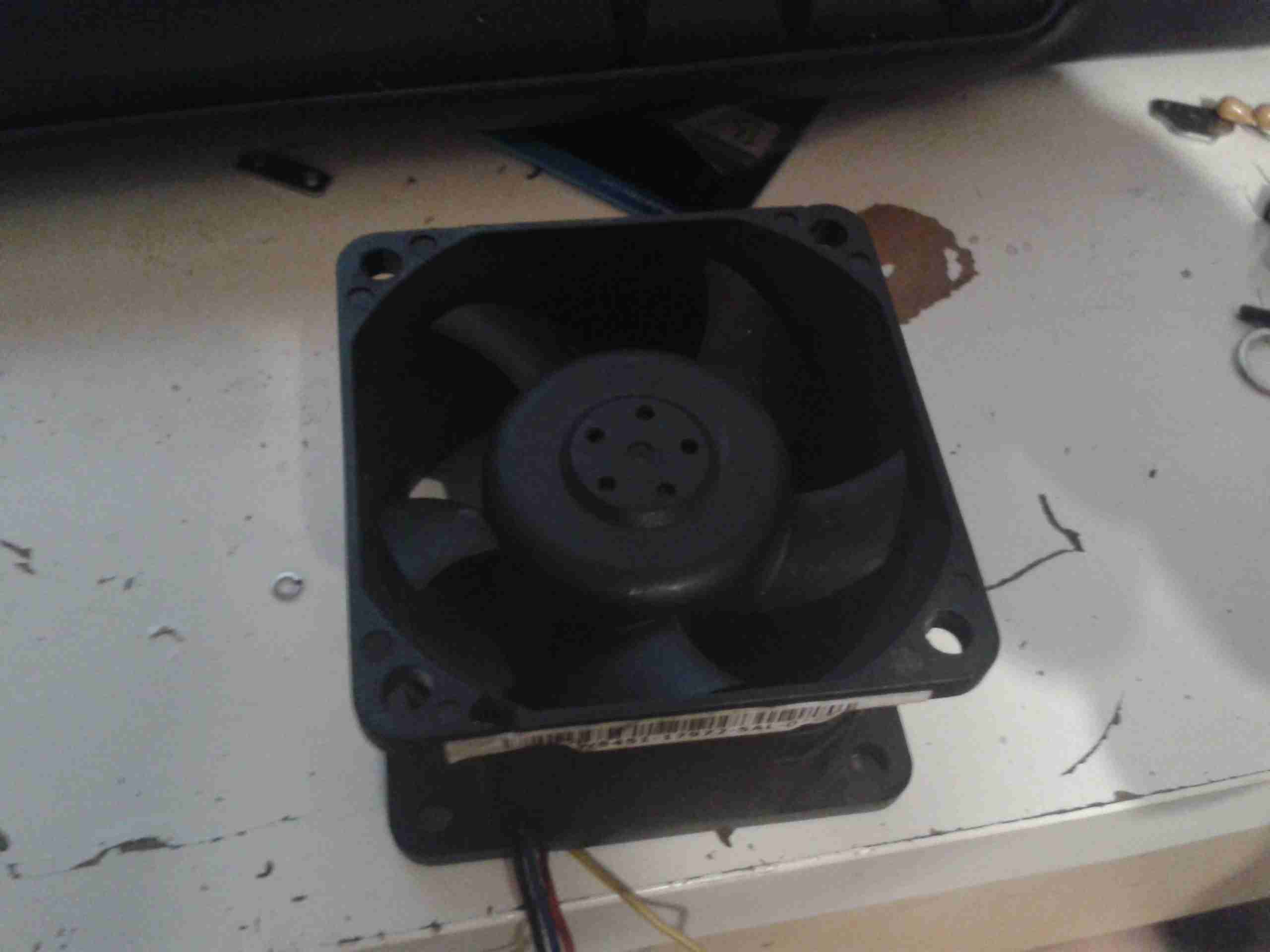
The solution of course, is a bigger fan – I’ve got some Delta AFB0612EHE server fans, these are very powerful axial units, shifting 60CFM at 11,000RPM, with a power draw of 1.12A.
They’re 60mm diameter, so only just fit into the back of the case – although they stick out of the back by 40mm.
Monster Fan
Here’s the fan, not the beefiest I have, but the beefiest that will fit into the available space.
These will easily take fingers off if they get too close at full speed, so guards will definitely be required.
To reduce the noise (they sound like jet engines at full pelt), I have ordered some PWM controllers that have a temperature sensor onboard, so I can have the fan run at a speed proportional to the PSU temperature. I will probably attach the sensor to the output rectifier heatsink, since that’s got the highest thermal load for it’s size.
This is basically an industrial, rugged MP3 player, in an extruded aluminium case.
They are used in commercial settings for generating telephone hold music or continual playback of background music in shops.
USB1100
It’s quite a compact unit, in a nice aluminium case, designed for mounting into a comms setup. This unit will play any MP3 file, up to a maximum size of 11MB.
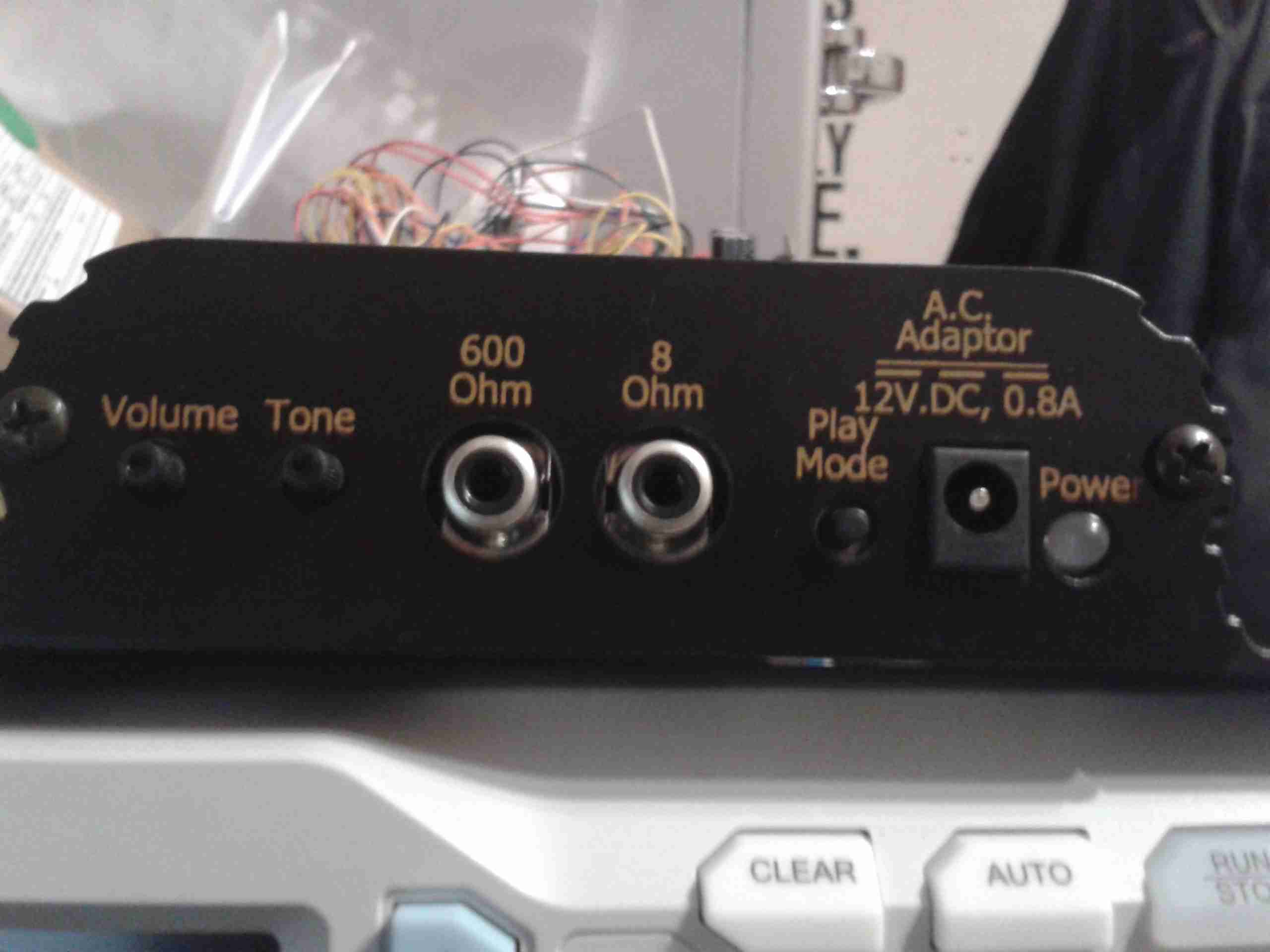
Connections
Here’s the user connections on the end of the unit. The device takes a standard 12v DC input, and has a single button for setup, user feedback is given through the multi-colour LED next to the power jack.
Both 8Ω & 600Ω audio outputs are provided for maximum compatibility. Volume & tone controls are also here.
On the other end of the unit is a single USB port for loading the audio files from a USB drive, and a reset button.
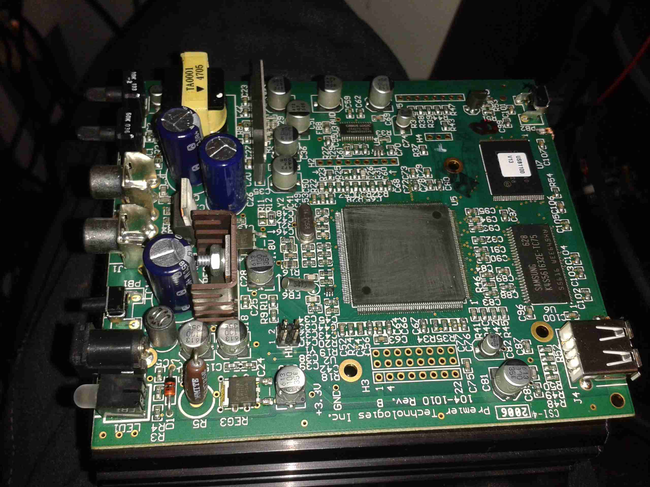
Main PCB
Here’s the single PCB removed from the casing. Unfortunately the main CPU has had it’s part number sanded off, and I can’t be bothered to try & find out what kind of processor it is at this point. To the right of the CPU are some flash ROM & SDRAM, along with the single USB port at bottom right.
The left side of the board is dedicated to audio output & voltage regulation, there are a fair few linear regulators in this unit.
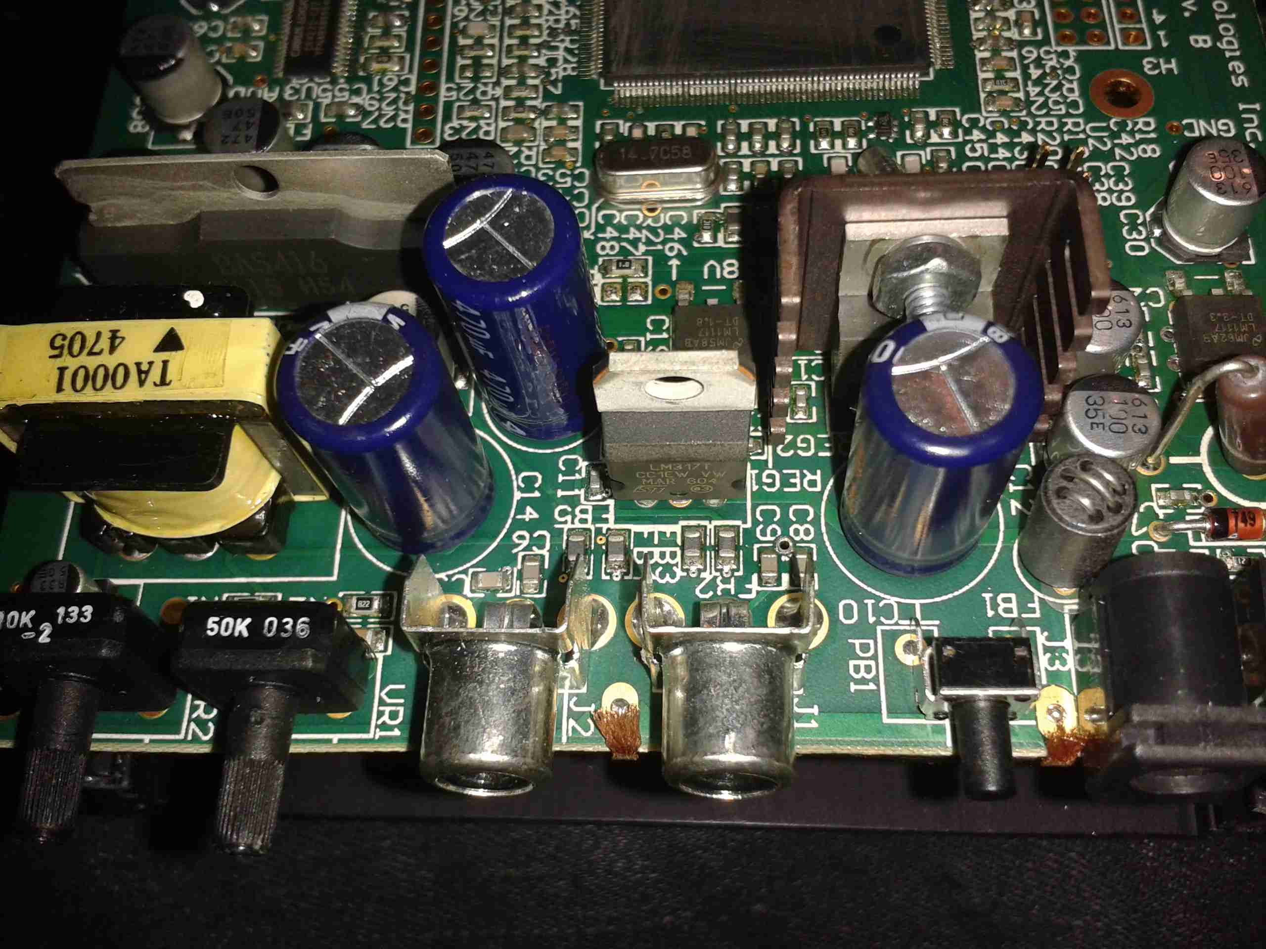
Audio End
Here’s the audio output side of the board, the transformer on the left is to provide the 600Ω output, the audio amplifier IC (BA5416) is just behind it. To the right are some of the main voltage regulators, a 5v one on the heatsink & a LM317.
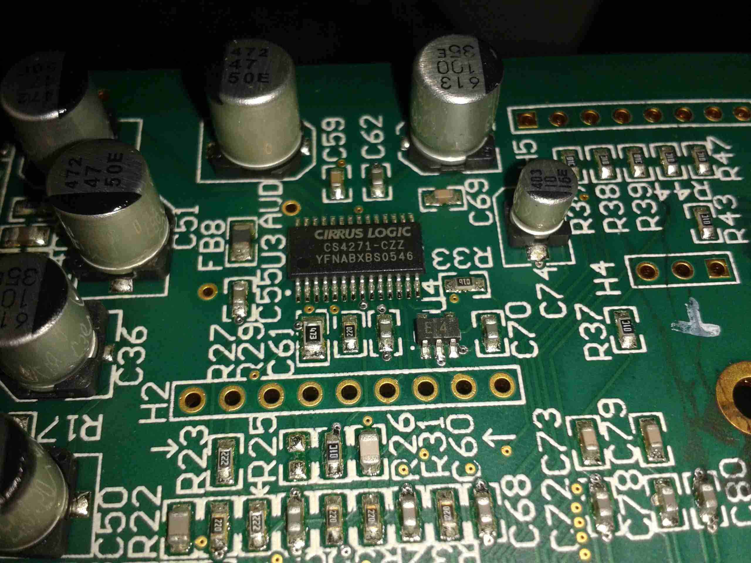
Audio Codec
The audio codec is a CS4271 from Cirrus Logic, a really high quality part, 24-bit resolution, 192kHz Stereo codec. Considering this is for telephone & PA systems that aren’t that high fidelity, it’s well built!
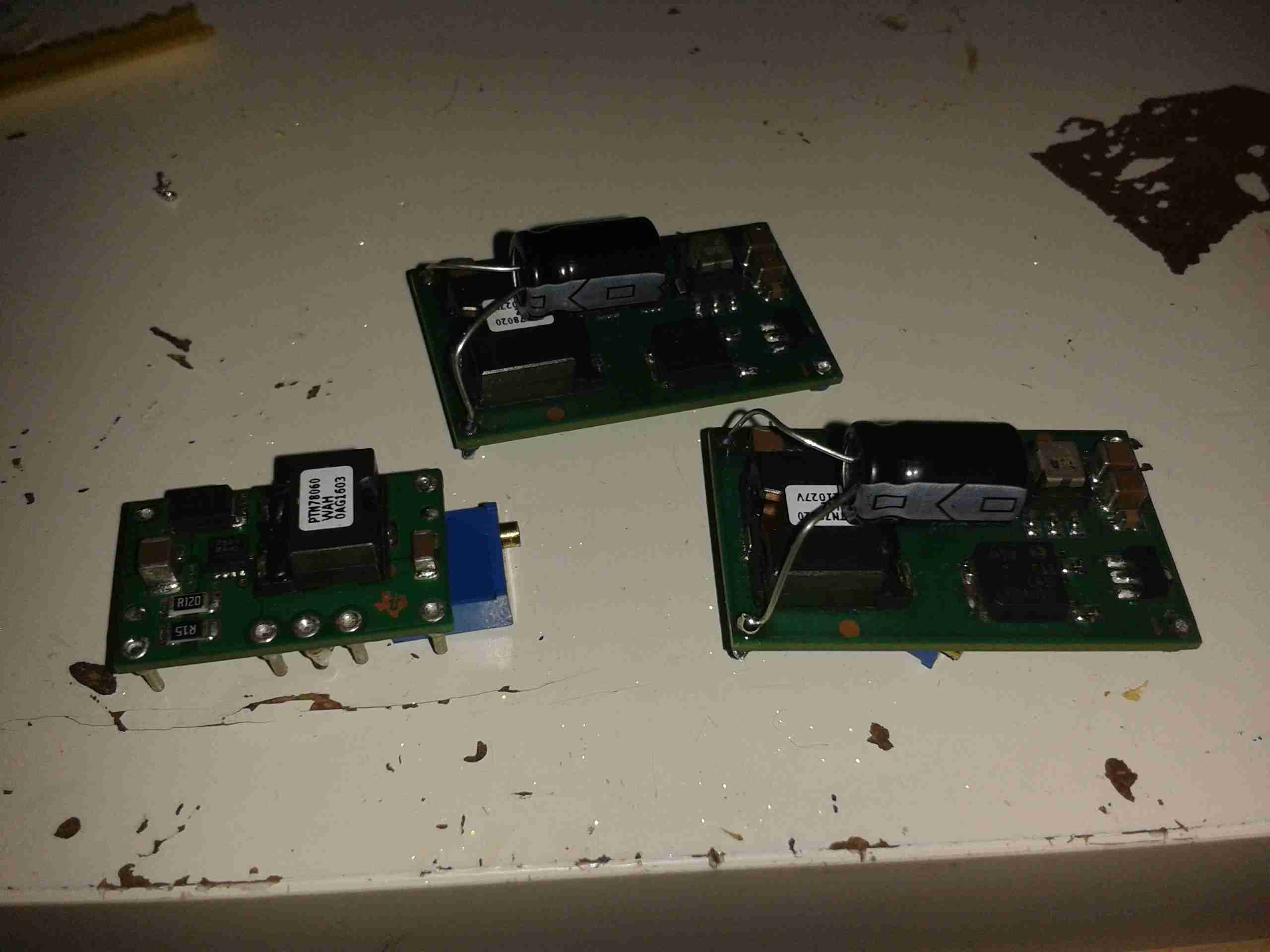
While searching around for regulators to convert my new scope to 12v power, I remembered I had some DC-DC modules from Texas Instruments that I’d got a while ago. Luckily a couple of these are inverting controllers, that will go down to -15v DC at 15W/3A capacity.
I’ve had to order a new module from TI to do the -17v rail, but in the meantime I’ve been getting the other regulators set up & ready to go.
The DC-DC module I’ve got for the -7.5v rail is the PTN78060A type, and the +7.5v & +5v rails will be provided by the PTN78020W 6A buck regulators.
These regulators are rated well above what the scope actually draws, so I shouldn’t have any issues with power.
DC-DC Modules
Here’s the regulators for the 5v, 7.5v & -7.5v rails, with multiturn potentiometers attached for setting the voltage output accurately. I’ve also attached a couple of electrolytics on the output for some more filtering. I’ll add on some more LC filters on the output to keep the noise down to an absolute minimum. These are set up ready with the exact same output voltage as the existing mains AC switching supply, when the final regulator arrives from TI I will put everything together & get some proper rail readings.
There won’t be a proper PCB for this, as I don’t have the parts in Eagle CAD, and I simply don’t have the energy to draw them out from the datasheets.
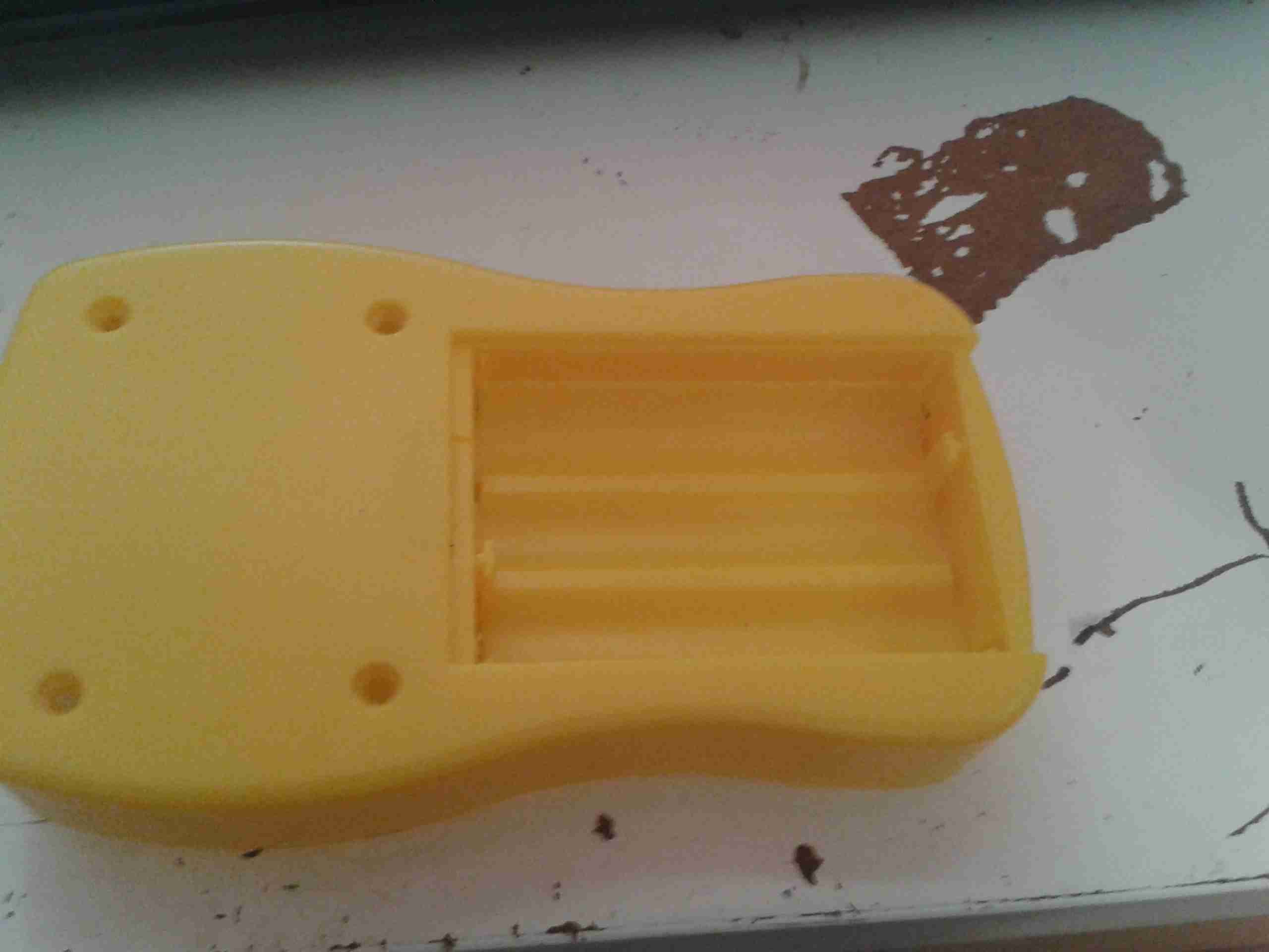
From the factory, the GY561 meter uses alkaline AAA cells for power. As these are not rechargable, and I don’t carry any other devices that take such batteries, I figured I’d replace them with a single Lithium Polymer cell that I can charge via USB.
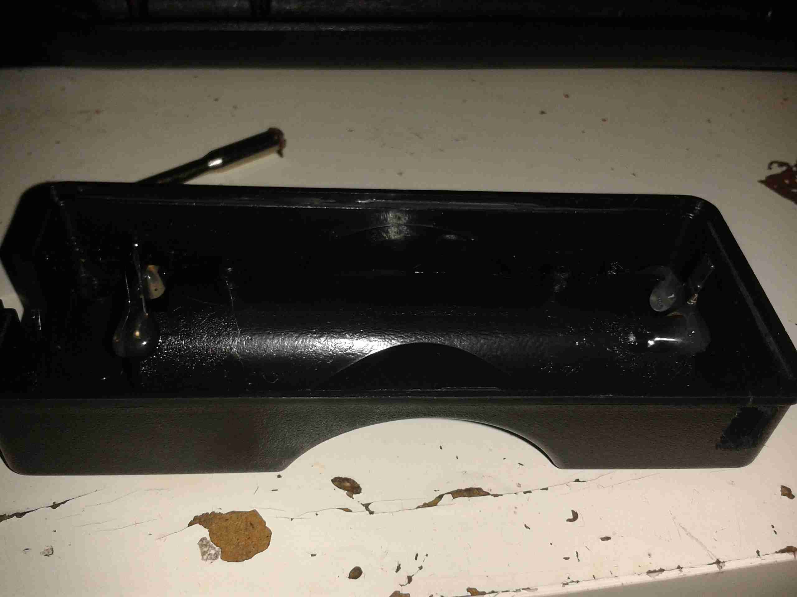
Battery Compartment
Here’s the battery compartment, with the original spring terminals removed.
I searched eBay for a suitable sized cell, and settled on a 1000mAh type, with dimensions of 47mm x 28mm x 7mm.
This size cell required a small amount of modification to the battery compartment to make it fit properly with the associated charge & protection circuitry.
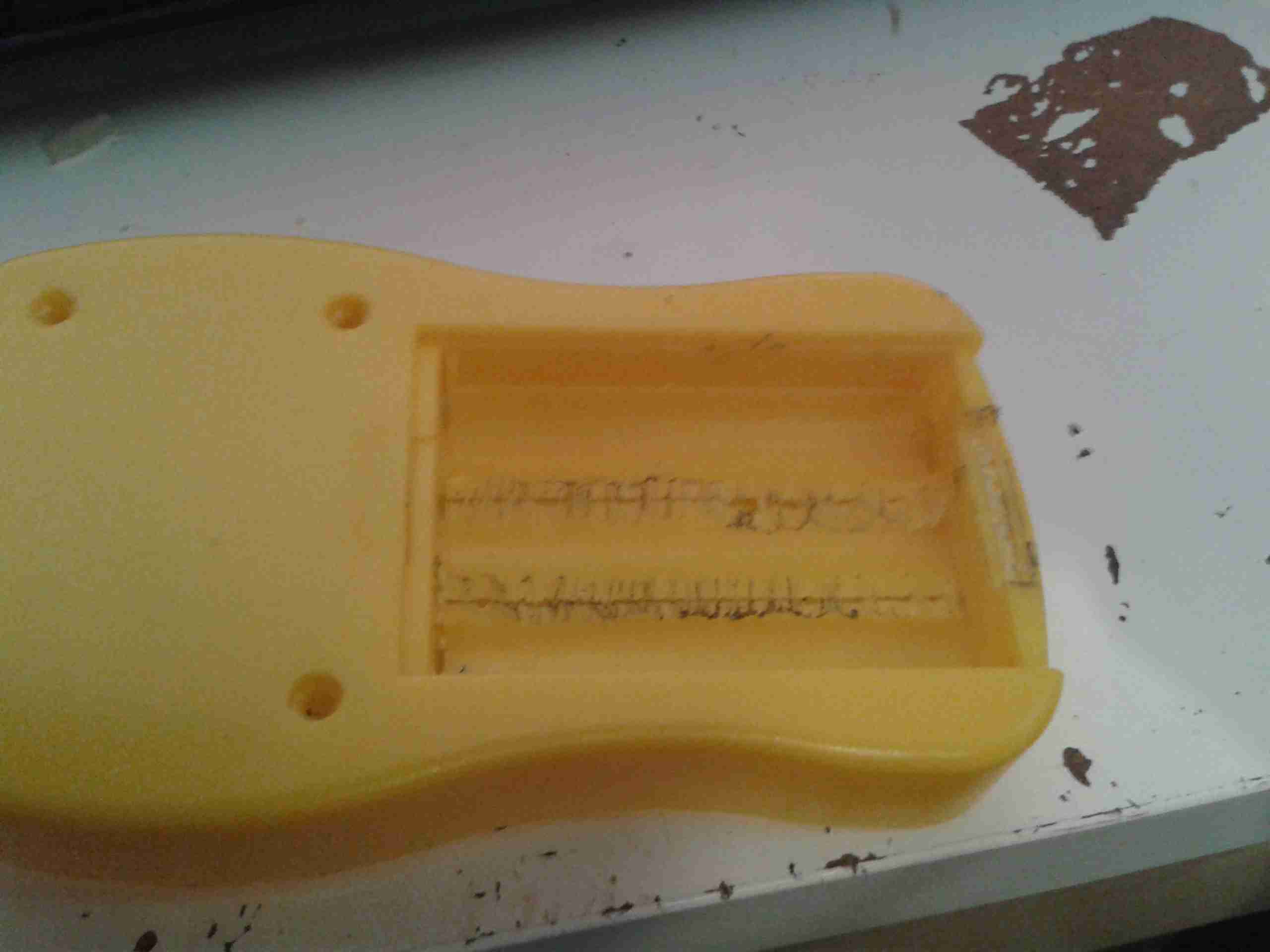
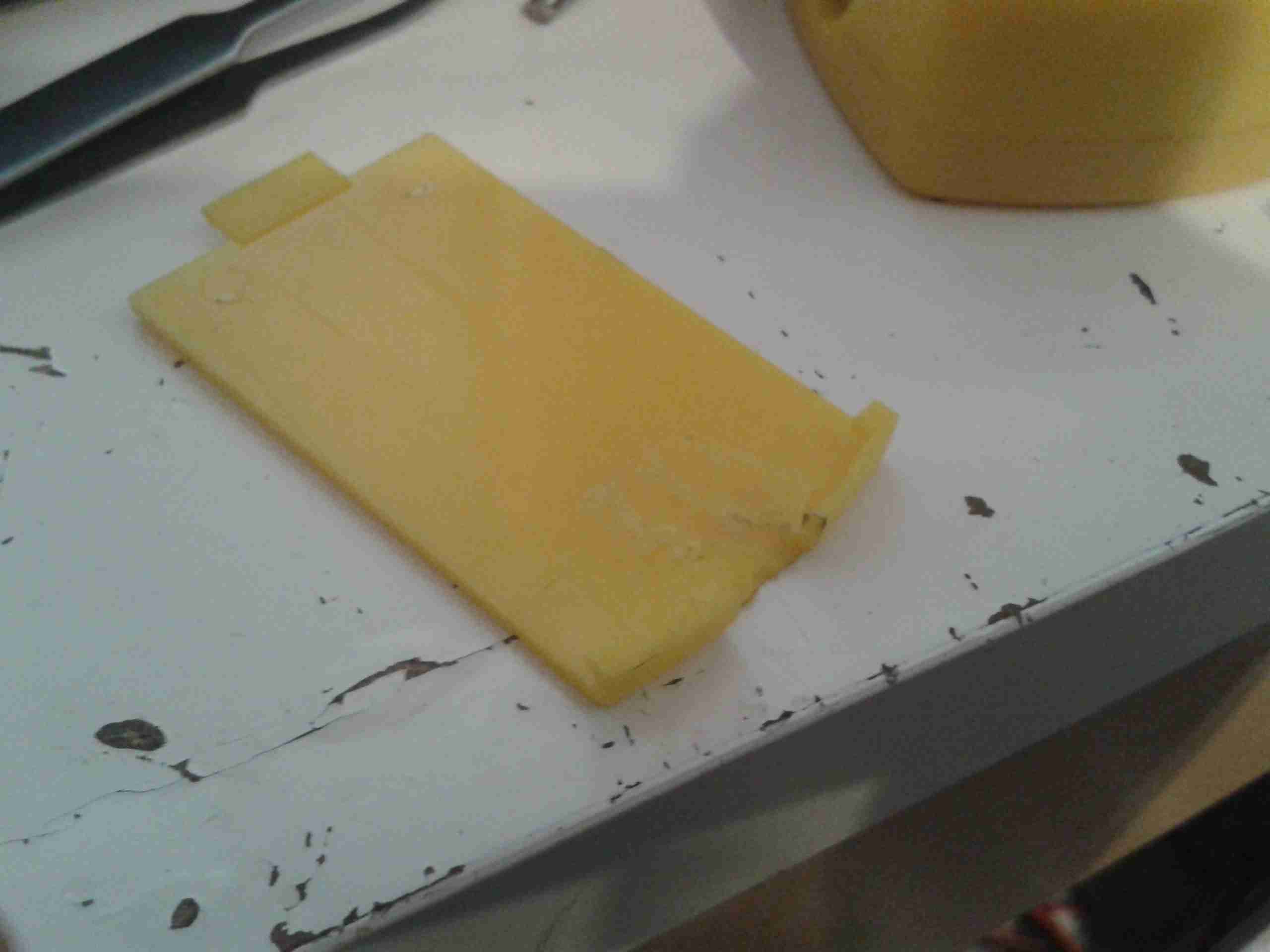
Modified Compartment
Here’s the modifications made to the compartment, I’ve ground away the plastic to make the bottom flat, and the plastic tabs that retained the original spring terminals.
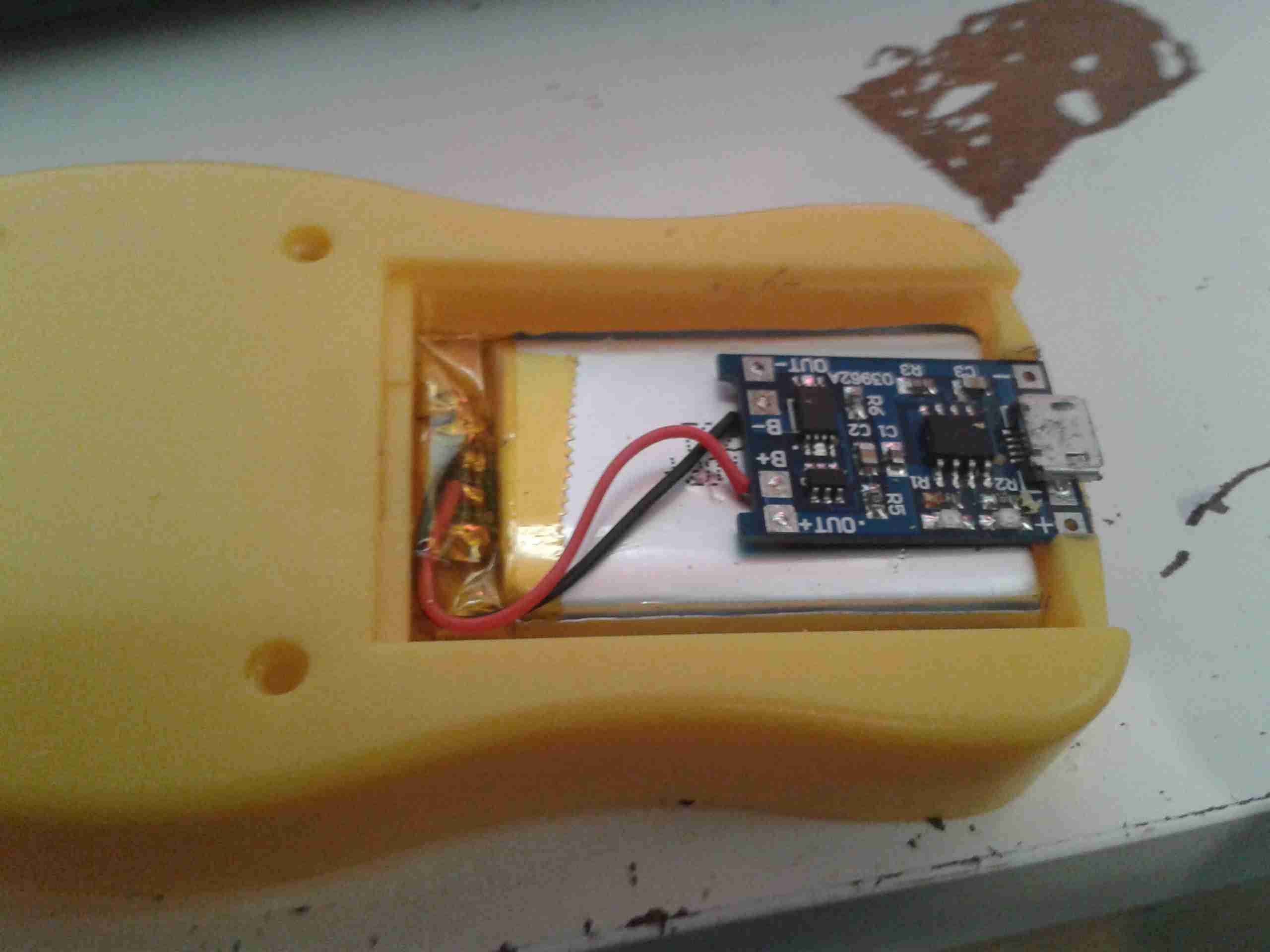
Modifications
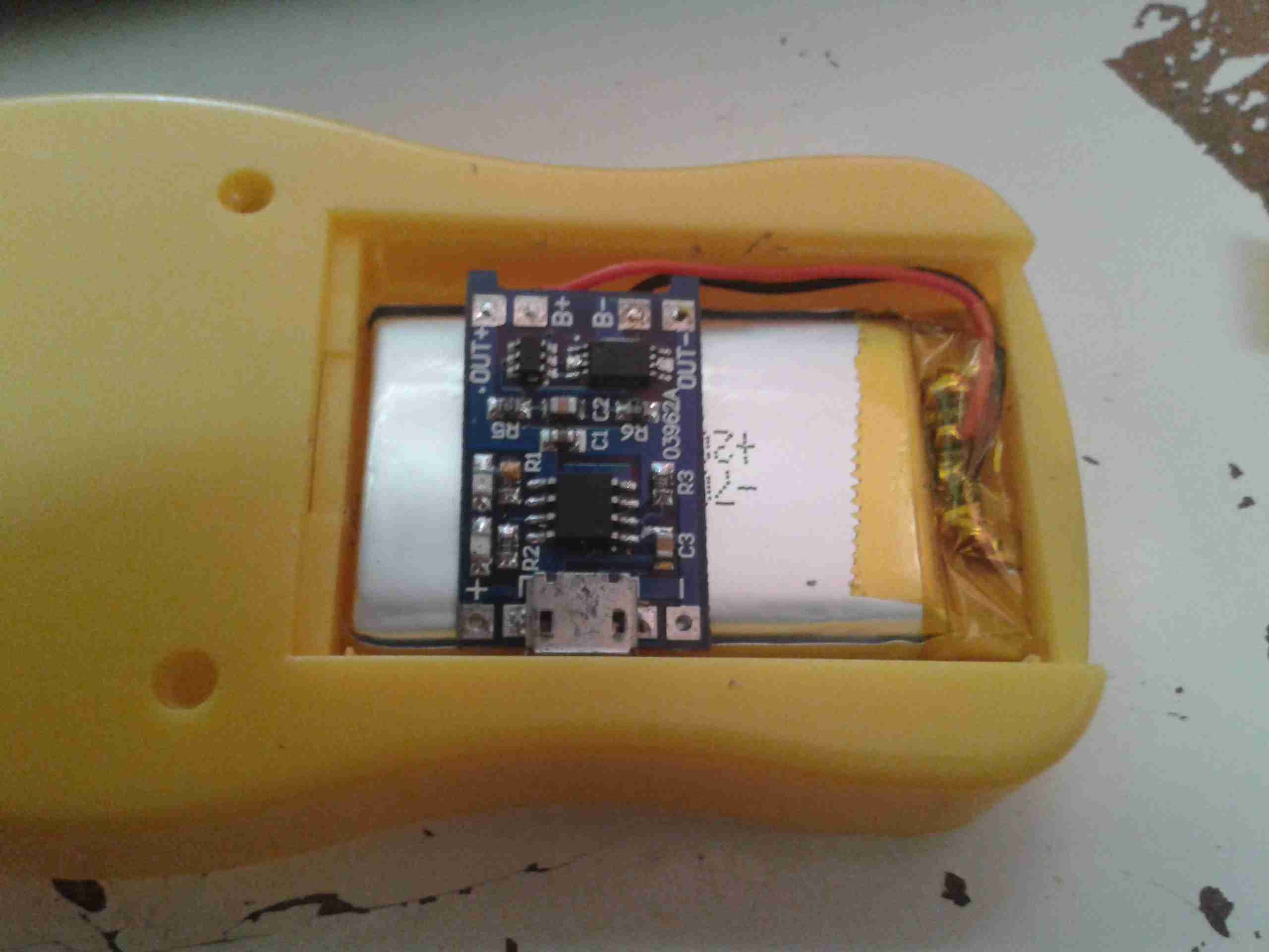
After grinding away the original battery spring holders with a dremel, the cell fits perfectly in the available space. The small PCB on the top of the cell is the USB charger & protection.
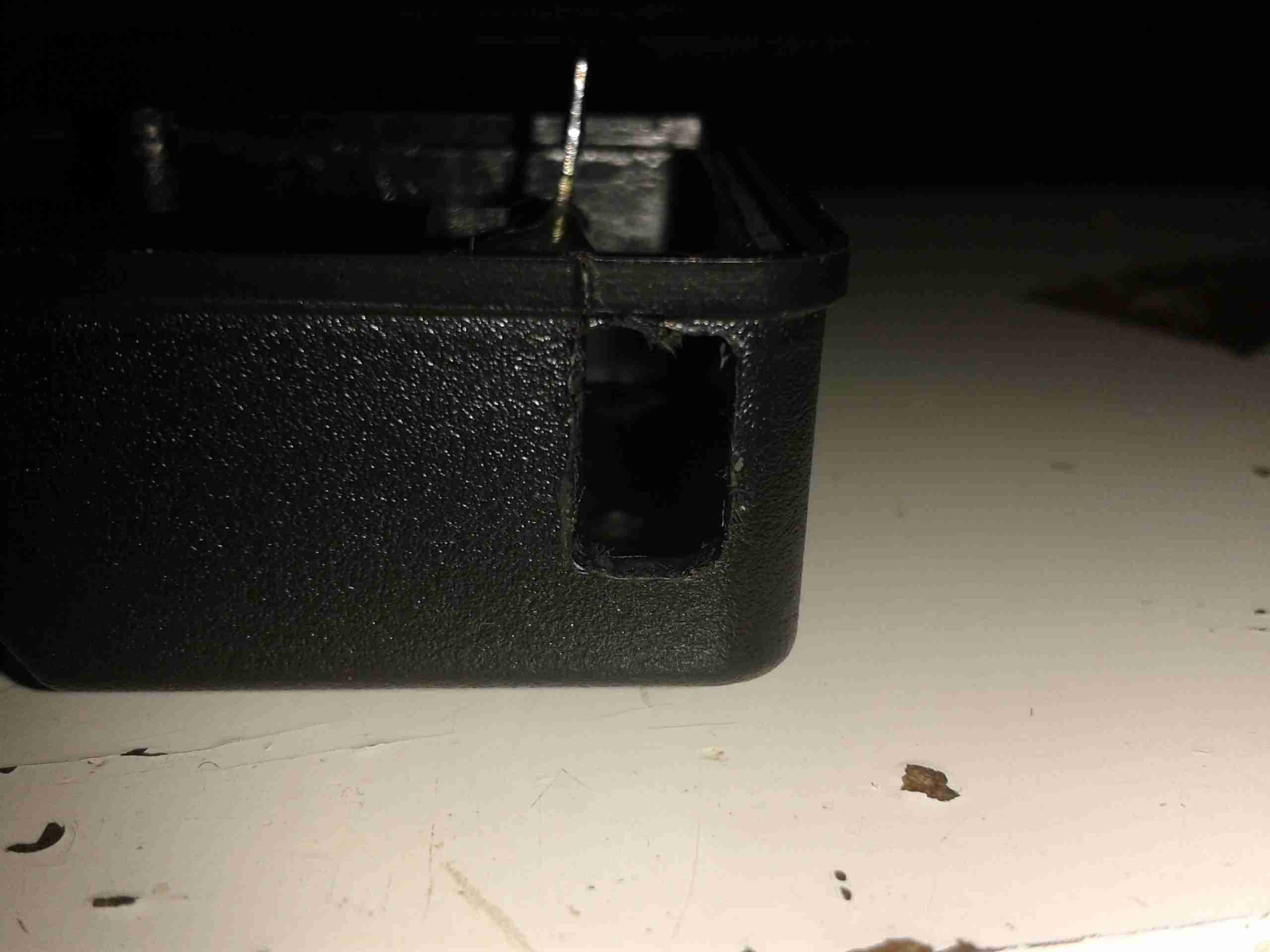
Charger
The charger is located in a slot cut in the bottom of the casing, so the USB port is accessible from outside the compartment.
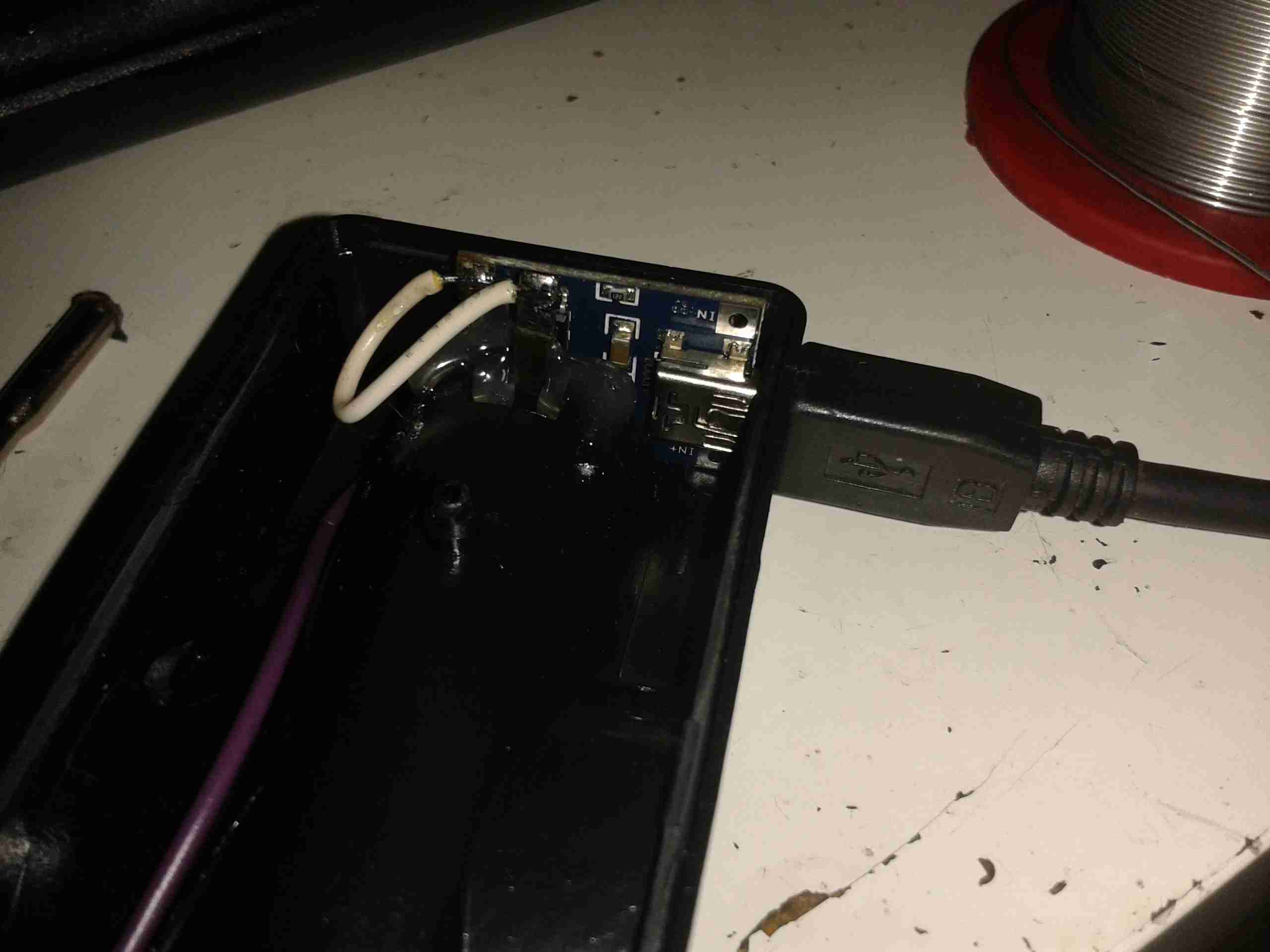
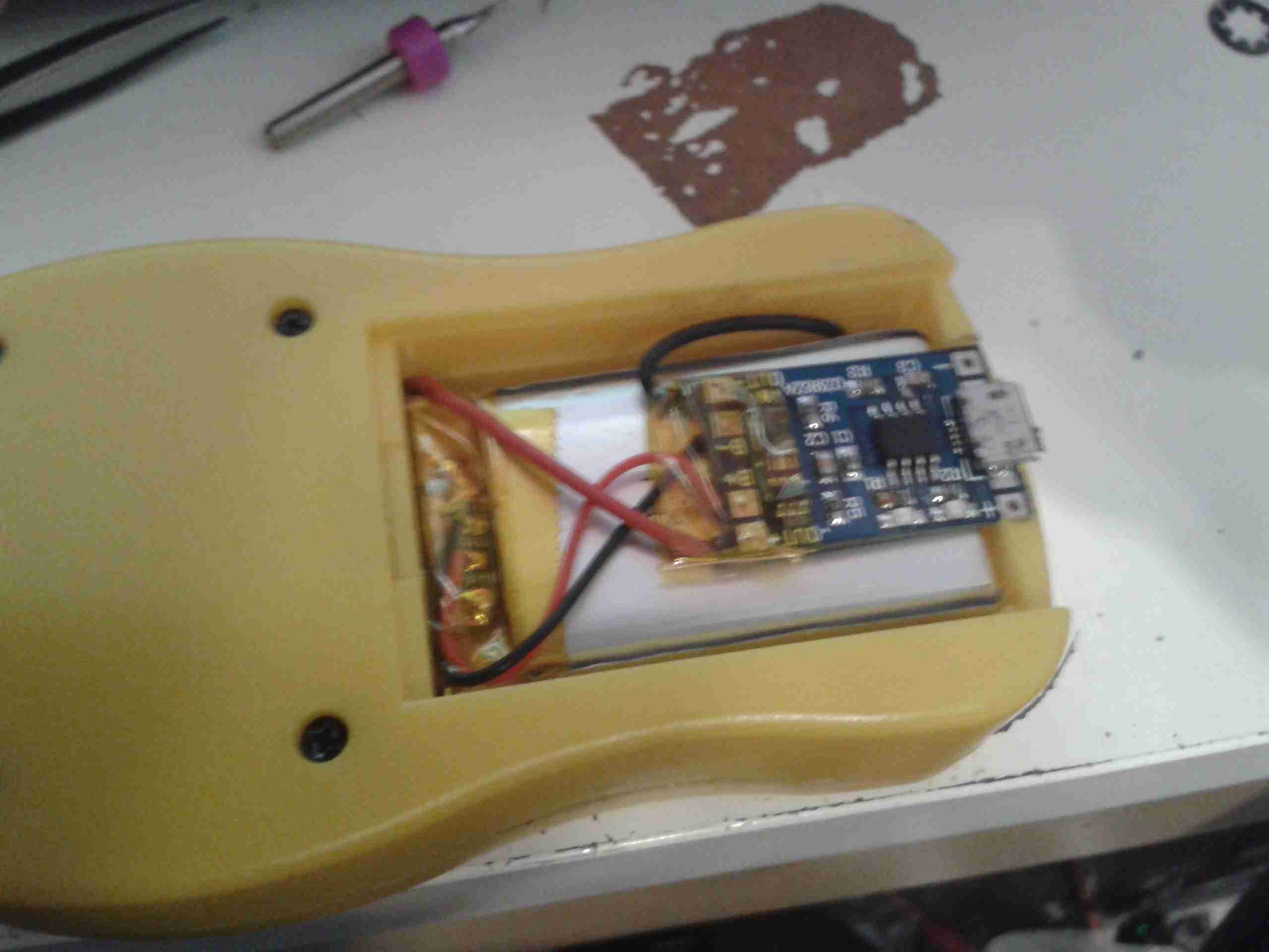
Wiring
Here’s the rest of the wiring completed, with the power wires going through holes in the bottom of the battery compartment to join onto the PCB where the original terminals were located. I have insulated the solder joints on the control PCB with some Kapton tape to prevent any shorts against the lithium cell.
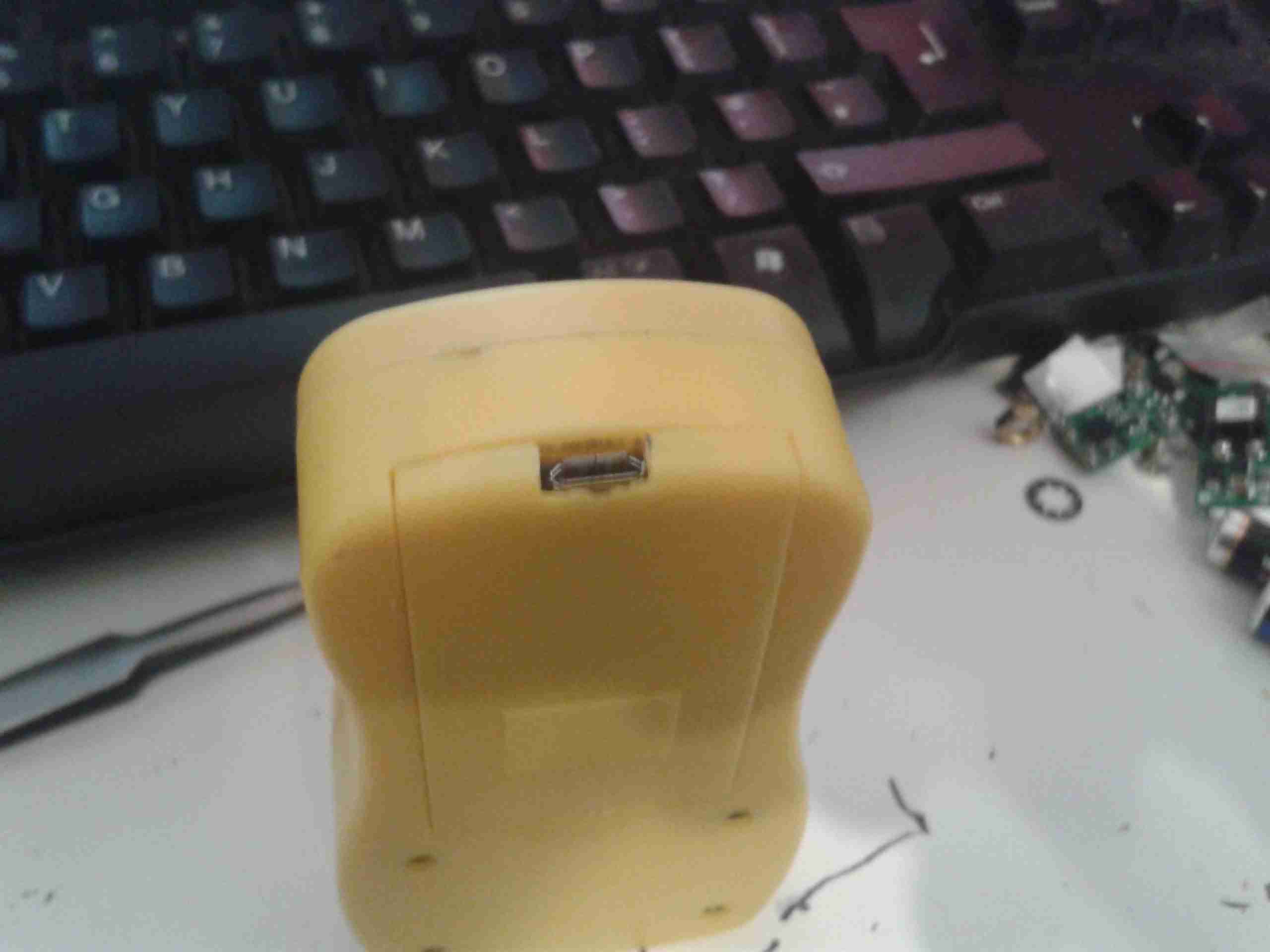
Battery Cover
A small cutout was also required in the battery cover to allow the USB connector to poke out. This was easy to do on the soft plastic with a Dremel tool.
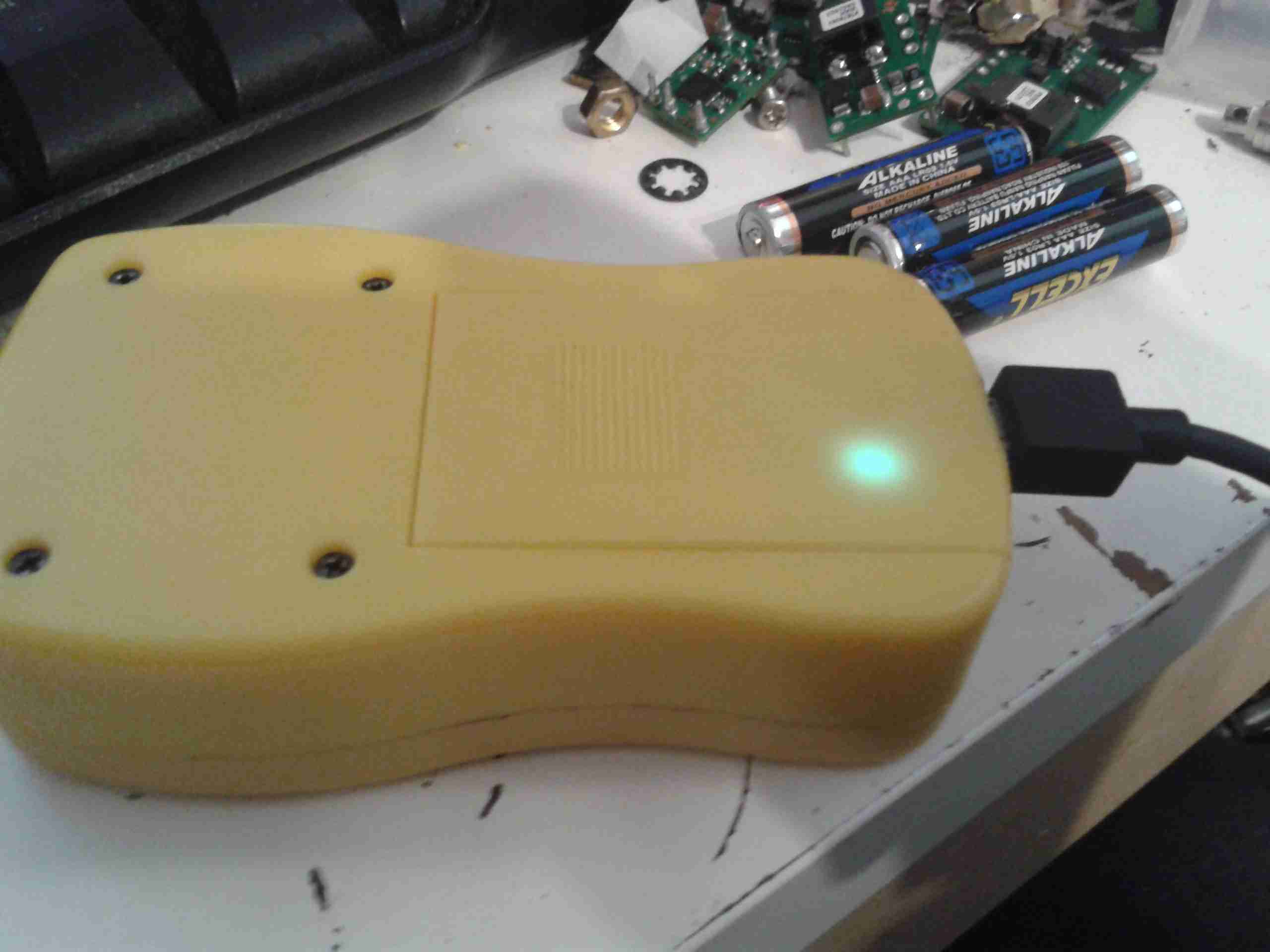
Charging Port
With the battery cover installed, the USB port is nicely recessed into the edge.
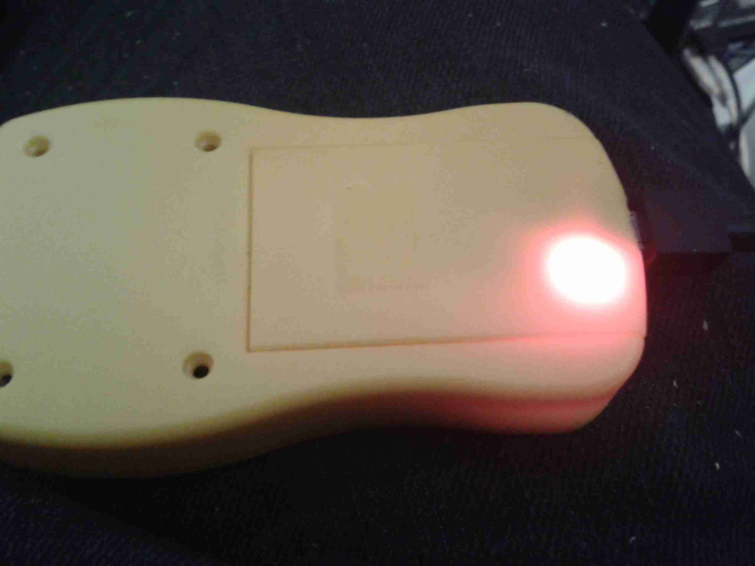
Charging LED
The indicator LEDs on the charging & control board show nicely through the plastic, here’s the unit on charge. When the charge is complete, another LED lights as shown below.
I really like the UV-82s, over the UV-5Rs I was originally using, so I’ve bought another pair. Here are the power levels on test. Tests were done with a full battery charge on the 2m/70cm calling frequencies.
Here’s an odd & sudden failure, the power adaptor for a Samsung device. It’s been working for months & on being plugged into the mains today the magic blue smoke escaped.
Samsung Charger
It’s one of their 2A models, for charging bigger devices like tablets.
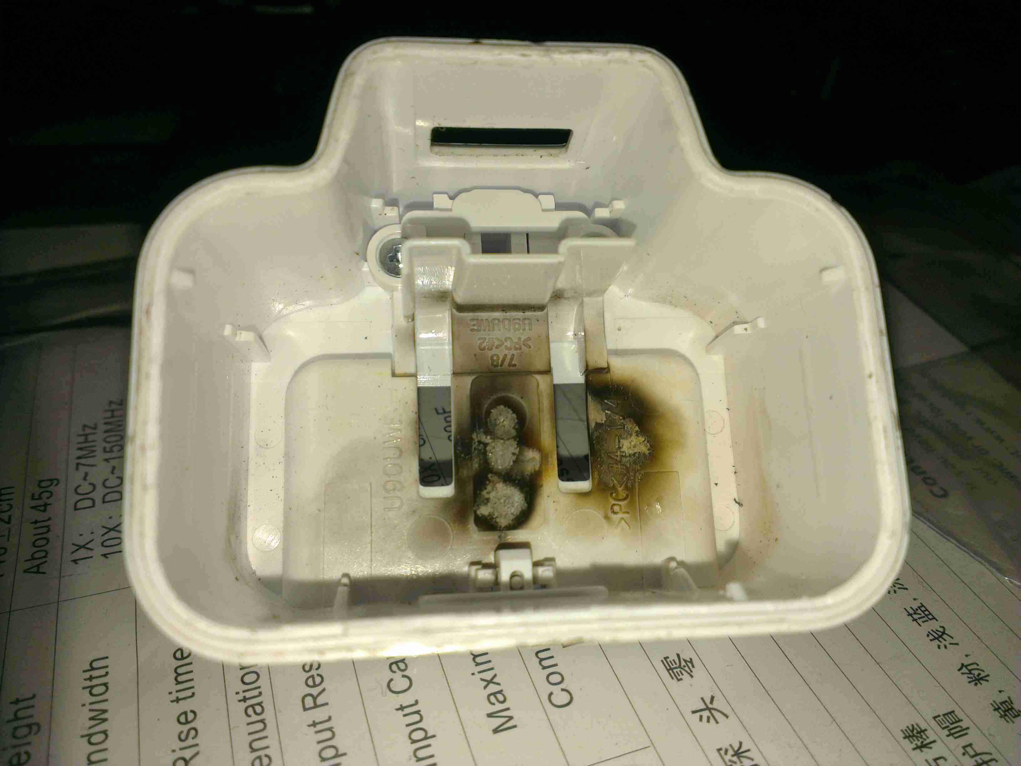
Flash Burn
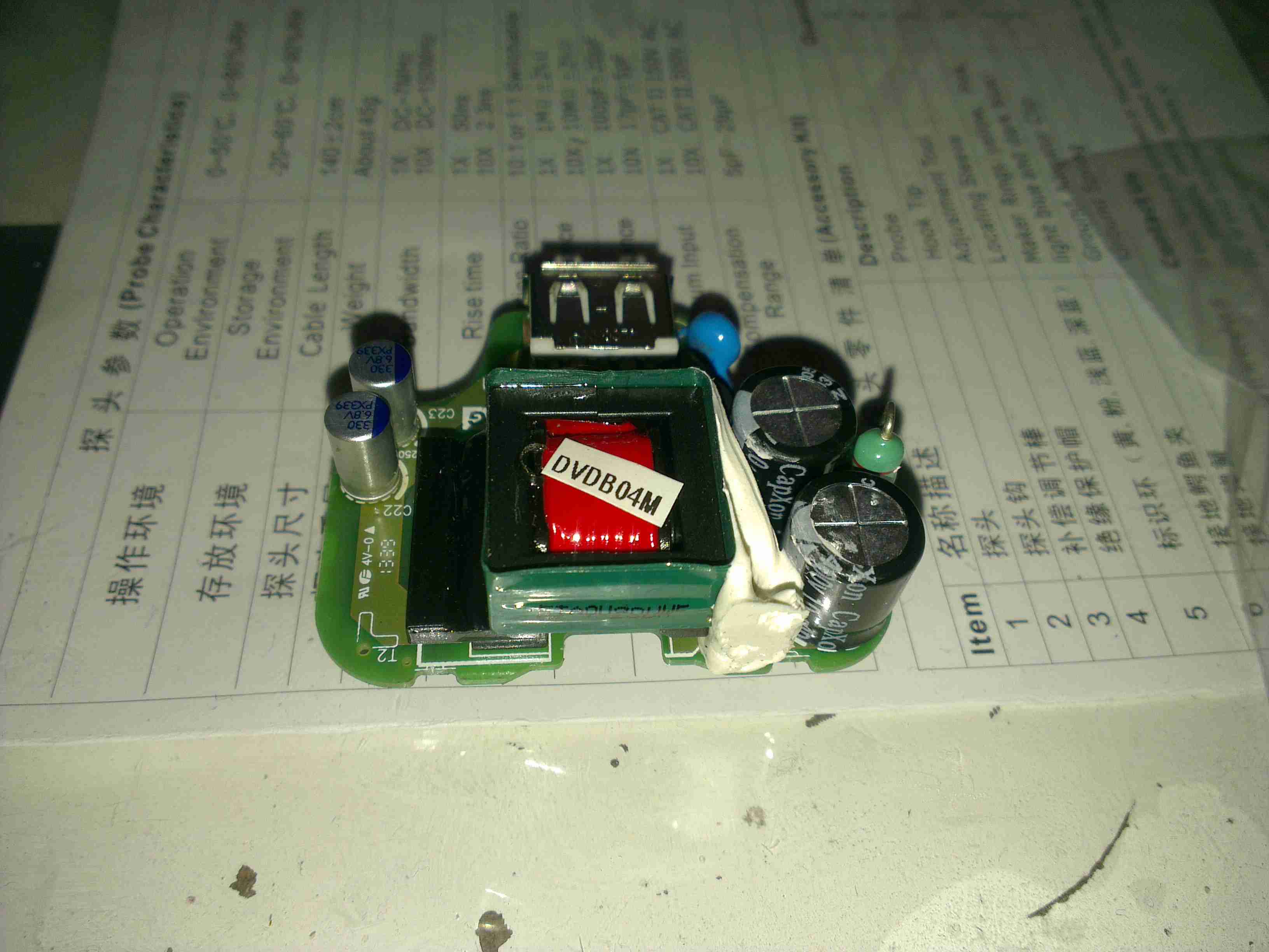
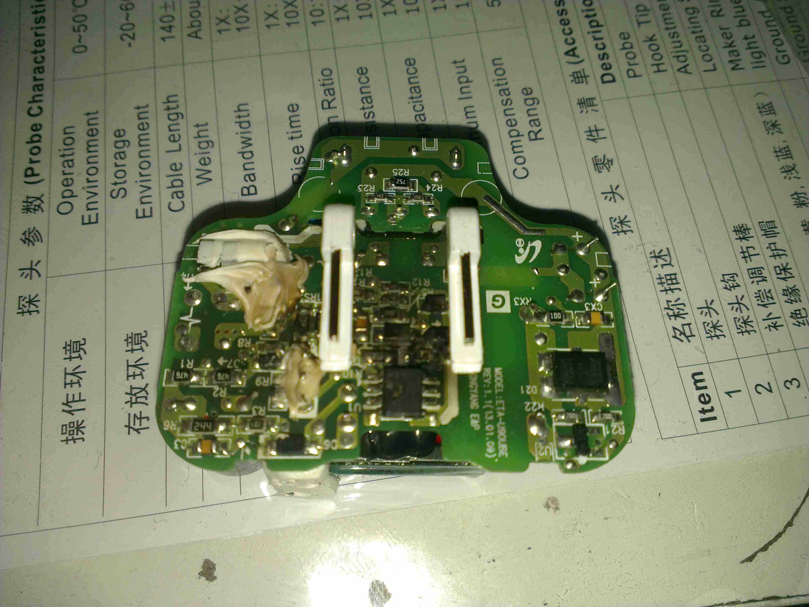
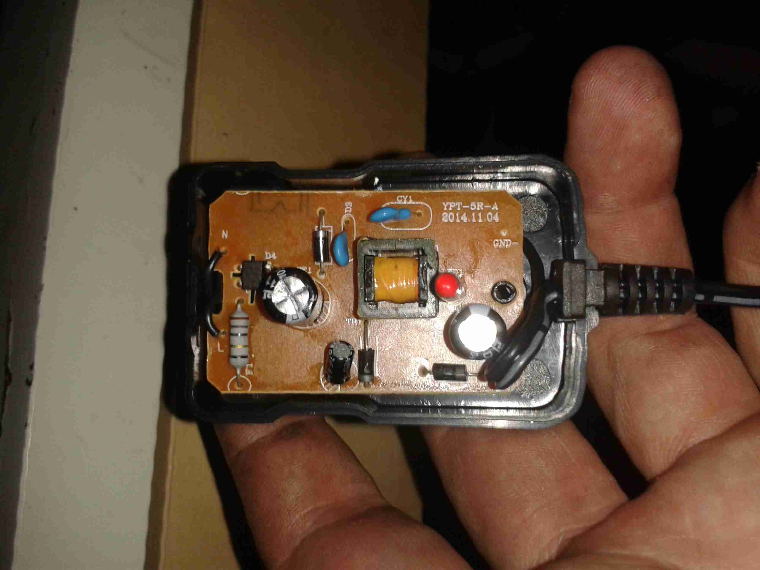
Strangely for one of these chargers, no glue is used to hold it together – just clips. This made disassembly for inspection much easier. Evidence of a rather violent component failure is visible inside the back casing.
PCB
Here’s the charger PCB removed from the casing. As to be expected from Samsung, it’s a high quality unit, with all the features of a well designed SMPS.
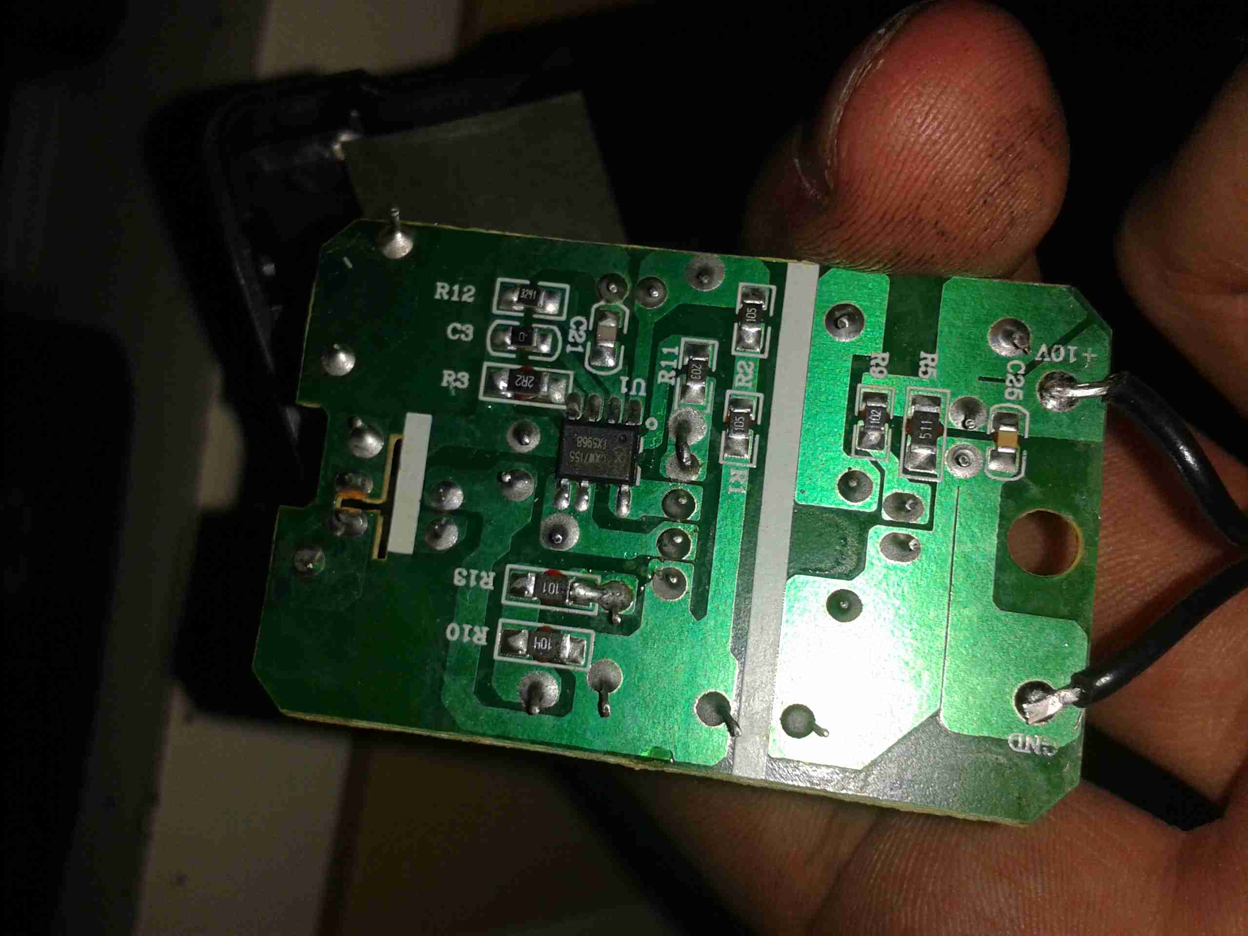
PCB Reverse
However, on turning the board over, the blown component is easily visible. It’s the main SMPS controller IC, with a massive hole blown in the top. The on board fuse has also blown open, but it obviously didn’t operate fast enough to save the circuit from further damage!
I recently dug out my other card printer to fit it with a 12v regulator, (it’s 24v at the moment), and figured I’d do a teardown post while I had the thing in bits.
This is a less industrial unit than my Zebra P330i, but unlike the Zebra, it has automatic duplexing, it doesn’t have Ethernet connectivity though.
Unlike domestic printers, which are built down to a price, these machines are very much built up to a spec, and feature some very high quality components.
Naked Printer
Here’s the mechanism with the cowling removed. This is the main drive side of the printer, with the main drive stepper at left, ribbon take-up spool motor lower right, and the duplex module stepper motors at far right.
Main Motor Drive
The main drive motor runs the various rollers in the card path through a pair of synchronous belts, shown here.
Main Stepper
The stepper itself is a quality ball-bearing Sanyo Denki bipolar motor.
Main Stepper Driver
Electrical drive is provided to the stepper with a L6258EX DMOS universal motor driver. This chip can also drive DC motors as well as steppers.
Ribbon Supply Spool
Here is the encoder geared onto the ribbon supply spool. This is used to monitor the speed the ribbon is moving relative to the card.
Printer Top
Here’s a top view through the printer, the blue roller on the left cleans the card as it’s pulled from the feeder, the gold coloured spool to it’s right is the ribbon supply reel. The cooling fan on the right serves to stop the print head overheating during heavy use.
Spool Take Up Motor
The spool take-up reel is powered by another very high quality motor, a Buhler DC gearmotor. These printers are very heavily over engineered!
This motor drives the spool through an O-Ring belt, before the gear above. This allows the drive to slip in the event the ribbon jams, preventing it from breaking.
Duplex Unit Stepper Drivers
The pair of steppers that operate the duplexing unit are driven by a separate board, with a pair of L6219DS bipolar stepper driver ICs. There are also a couple of opto-sensors on this board for the output hopper.
Main Control PCB
All the mechanisms of the printer are controlled from this main PCB, which handles all logic & power supply functions. Sections on the board are unpopulated, these would be for the Ethernet interface, smart card programming & magstripe programming.
Main CPU
The brains of the operation is this ColdFire MCF5208CVM166 32-bit microprocessor. It features 16KB of RAM, 8KB of cache, DMA controller, 3 UARTs, SPI, 10/100M Ethernet and low power management. This is a fairly powerful processor, running at 166MHz.
It’s paired with an external 128Mbit SDRAM from Samsung, and a Spansion 8Mbit boot sector flash, for firmware storage.
USB Interface & Power Input
Here the USB interface IC is located. It’s a USBN9604 from Texas Instruments, this interfaces with the main CPU via serial.
I often find myself carrying by go bag up to the boat during trips, so I can do some radio. However at 16lbs it’s a pain on public transport. A fixed radio was required! Another Wouxun GK-UV950P was ordered, and the fact that the head unit is detachable from this radio makes a clean install much easier.
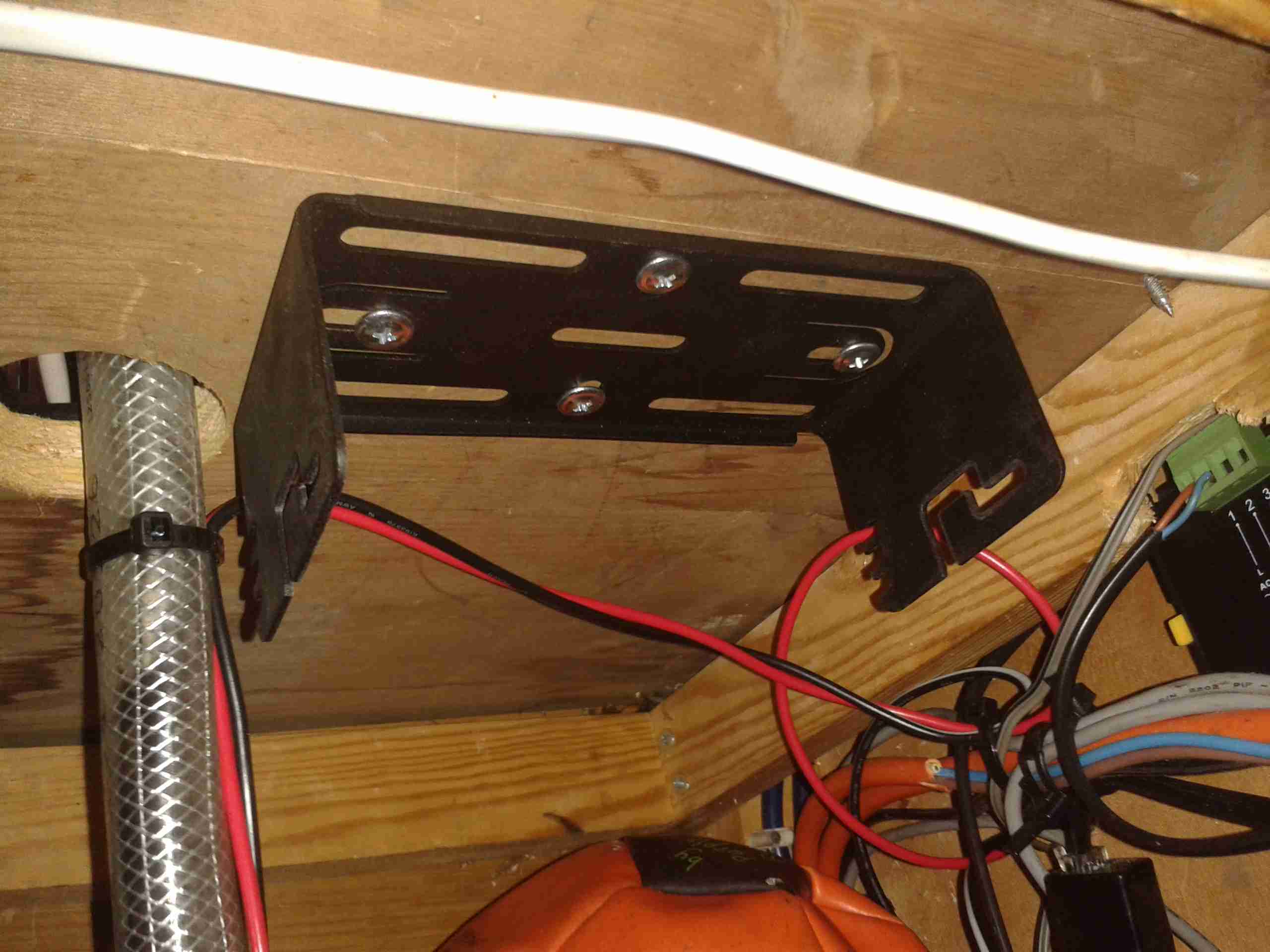
Mounting Bracket
I found a nice spot under a shelf for the main radio unit, above is the mounting bracket installed.
This location is pretty much directly behind where the head unit is placed, but the audio is a bit muffled by the wooden frame of the boat & some external speakers will be required for the future.
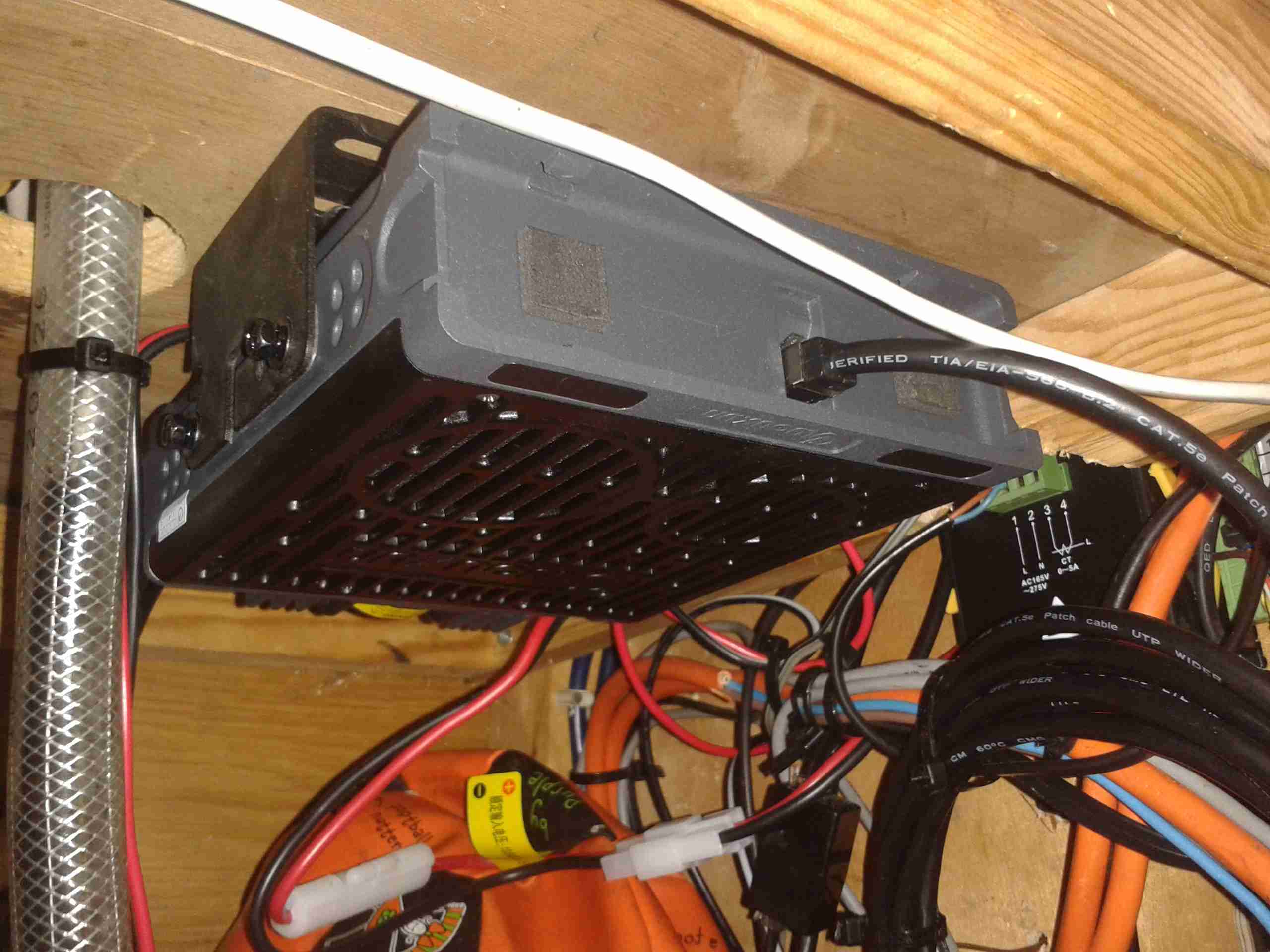
Main Radio Unit
Here’s the main radio unit mounted on it’s bracket, with the speakers facing down to improve the audio slightly. I used the supplied interface cable for the head unit, even though it’s too long. I do have the tools to swage on new RJ-45s, but the stuff is a pain to terminate nicely & I really just couldn’t be bothered. So it’s just coiled up with some ties to keep it tidy. Main power is provided directly from the main DC bus. (880Ah total battery capacity, plus 90A engine alternator, 40A solar capacity).
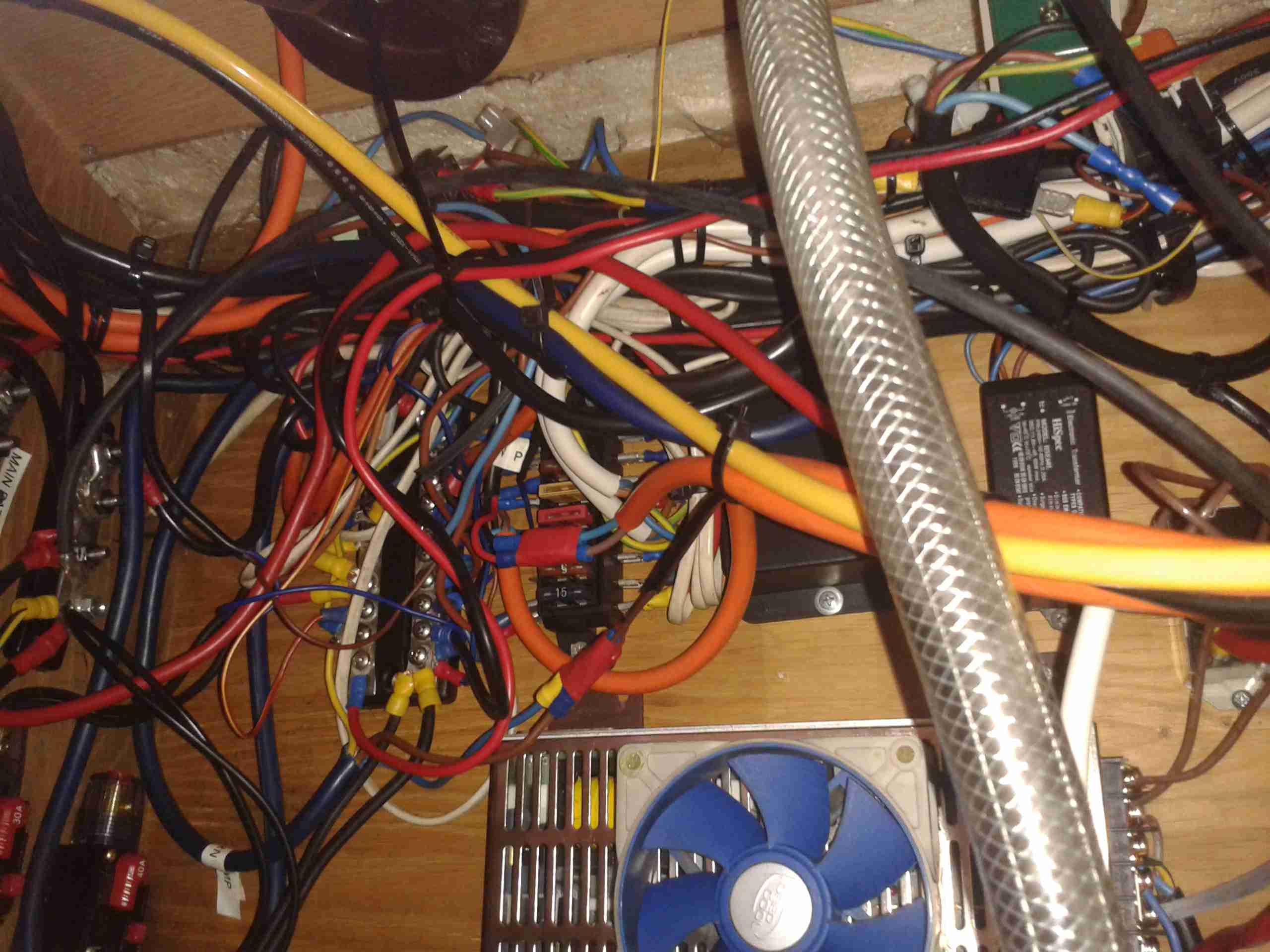
Rat’s Nest
Here’s the main DC bus, with the distribution bars. With the addition of new circuits over the years, this has become a little messy. At some point some labelling would be a good idea!
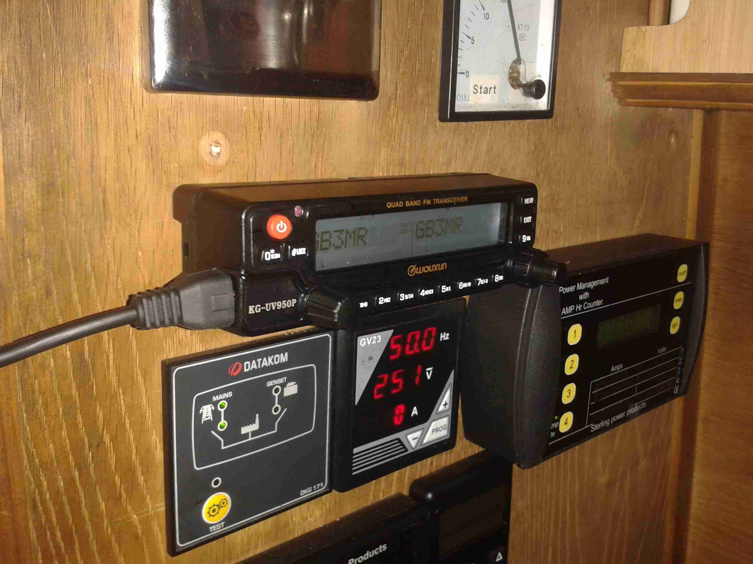
Radio Face Plate
Finally, the head unit is installed in a spot on the main panel. It does stick out a little more than I’d like, but it’s a lot of very dusty work with the router to make a nice hole to sink it further in. All my local repeaters & 2m/70cm simplex are programmed in at the moment.
Antenna Magmount
I’ve got a Nagoya SP-80 antenna on a magmount for the radio, a magmount being used due to the many low bridges & trees on the canal. (It’s on the roof next to the first solar panel above). I prefer it to just fall over instead of having the antenna bend if anything hits it!
Part 2 will be coming soon with details of the permanent antenna feeder.
With every piece of Chinese electronics I obtain, mainly Baofeng radios, they come with a Europlug-type power adaptor, and a universal plug adaptor for the mains.
The charger units aren’t too bad, there’s a fair amount of isolation between the primary & secondary, and even though they’re very simple & cheap, I can’t see any immediate safety problems with them.
The plug adaptors, however, are a different matter. These things are utterly lethal!
Baofeng PSU
Here’s the inside of the PSU. It’s just a very simple SMPS, giving an output of 10v 500mA. The fuse is actually a fusible resistor.
PCB Reverse
Here’s the back of the PCB with the SMPS control IC. I can’t find any English datasheets for this part unfortunately.
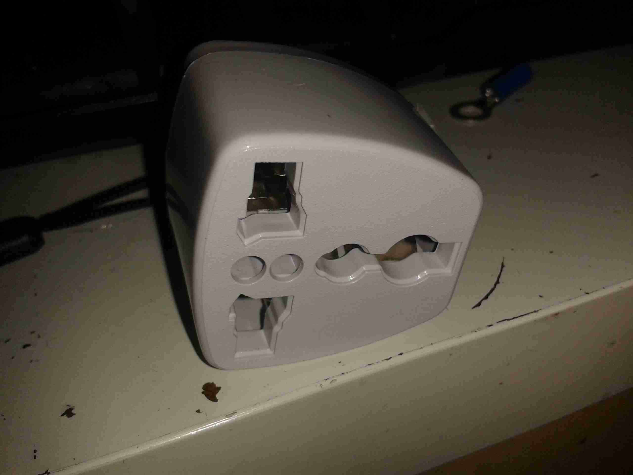
Universal Travel Adaptor
Here’s the dangerous adaptor. There’s no safety shield, so the live parts are exposed.
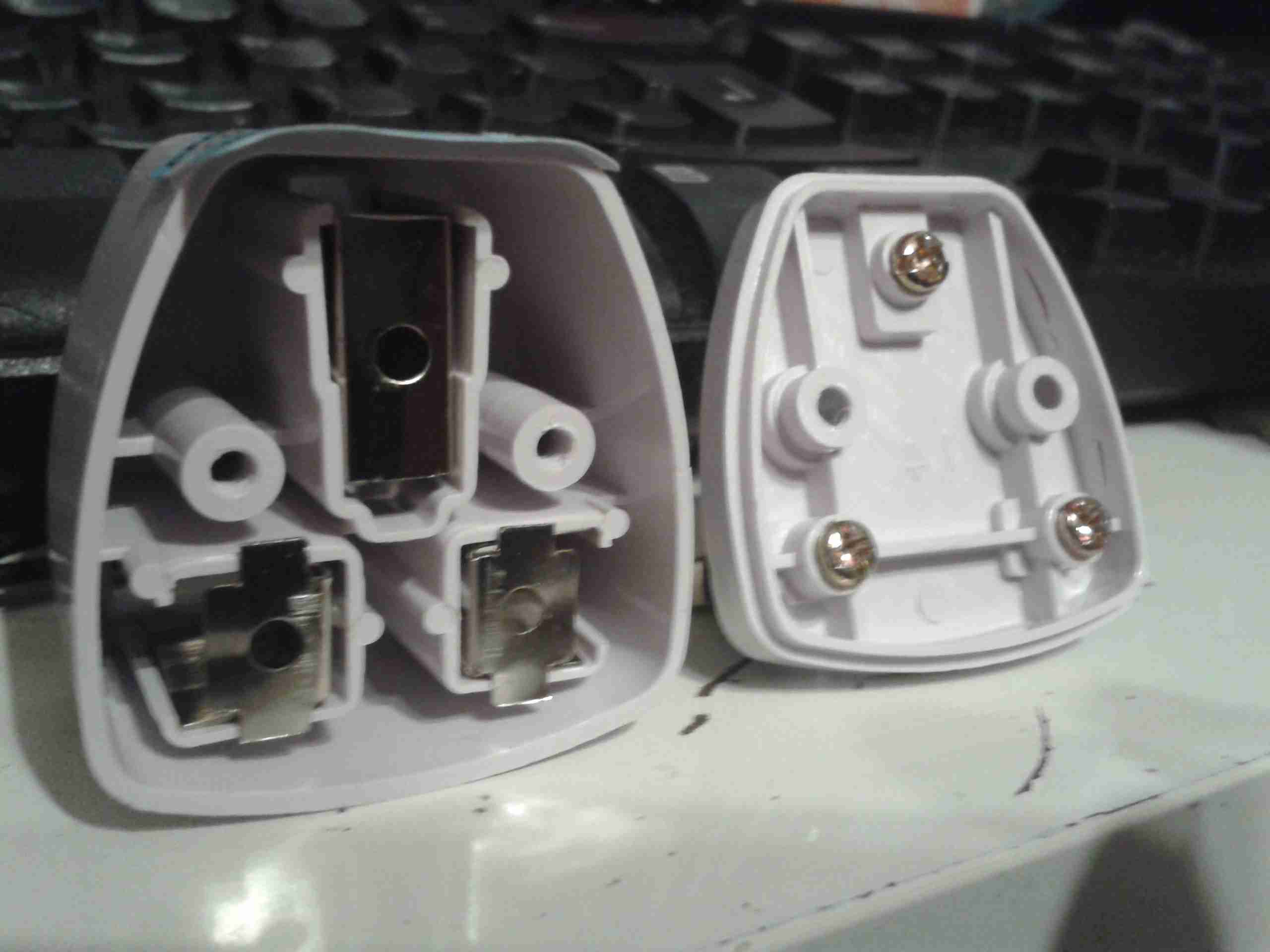
Internals
Here’s the adaptor split apart. The output contacts are on the left, and rely just on pressure to make contact with the brass screws on the mains input pins to provide power.
This is a very poor way to get a connection, a dirty or worn contact here would create a lot of heat if any significant power is pulled through, and could quite possibly result in a fire.
Not surprisingly, I bin these things as soon as I open the box, and charge all my radios with a 12v charging system.
Thanks to Lewis over at Distant Signal Radio, the bad influence he is on my bank balance ;), I’m the proud new owner of a new Baofeng. This time it’s the UV-82.
This radio is a little different from the other Baofengs I have. Here are the main differences:
Dual PTT – This one is going to take some getting used to 😉
Higher capacity battery pack
A more rugged, commercial feel
This radio has a different method of selecting the VFO mode – holding the menu key while the unit is powered on. This is a little awkward, but since I only usually use my local repeaters when I’m mobile, it’s not much of an issue.
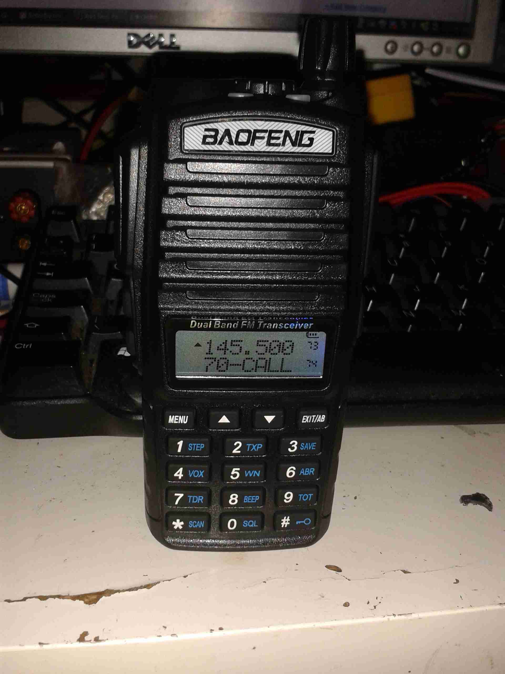
UV-82
Here’s the radio itself, it has a much more commercial feel to it than the UV-5Rs, and it’s slightly bigger. Mainly due to the use of a larger standard battery & larger loudspeaker.
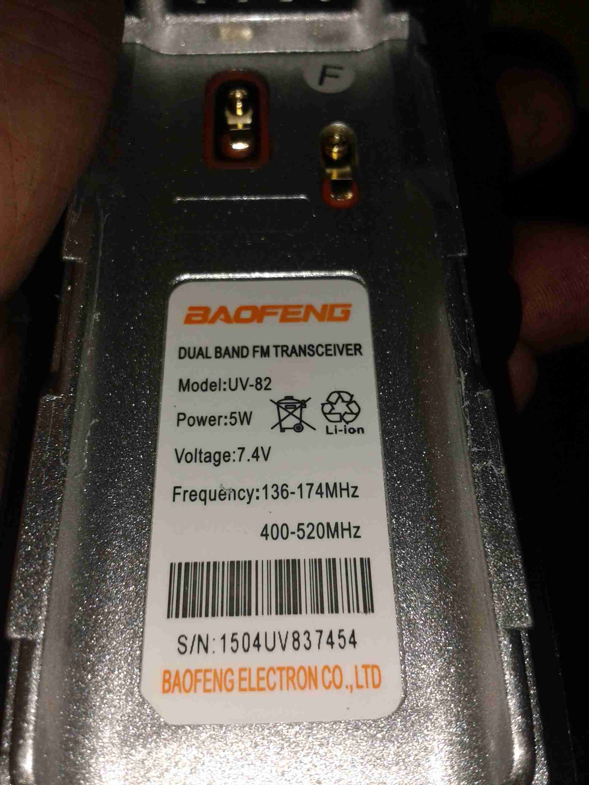
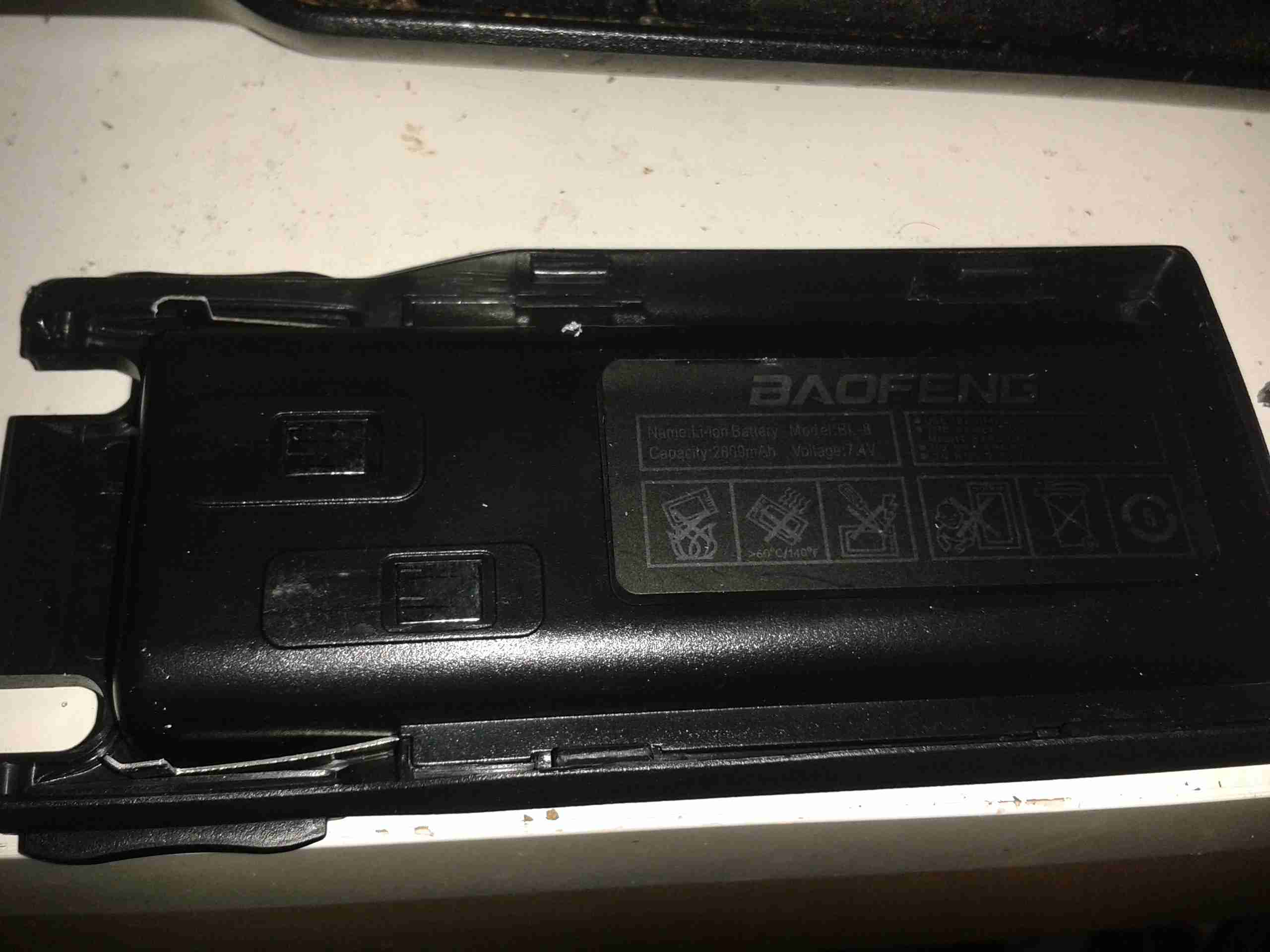
Spec Label
Back of the unit with the spec label. As per usual Baofeng are a bit conservative with the power ratings, more to come on that below.
Battery Pack
Here’s the battery pack, a 2-cell lithium-polymer unit. This has a bigger capacity than the standard UV-5R battery, at 2800mAh.
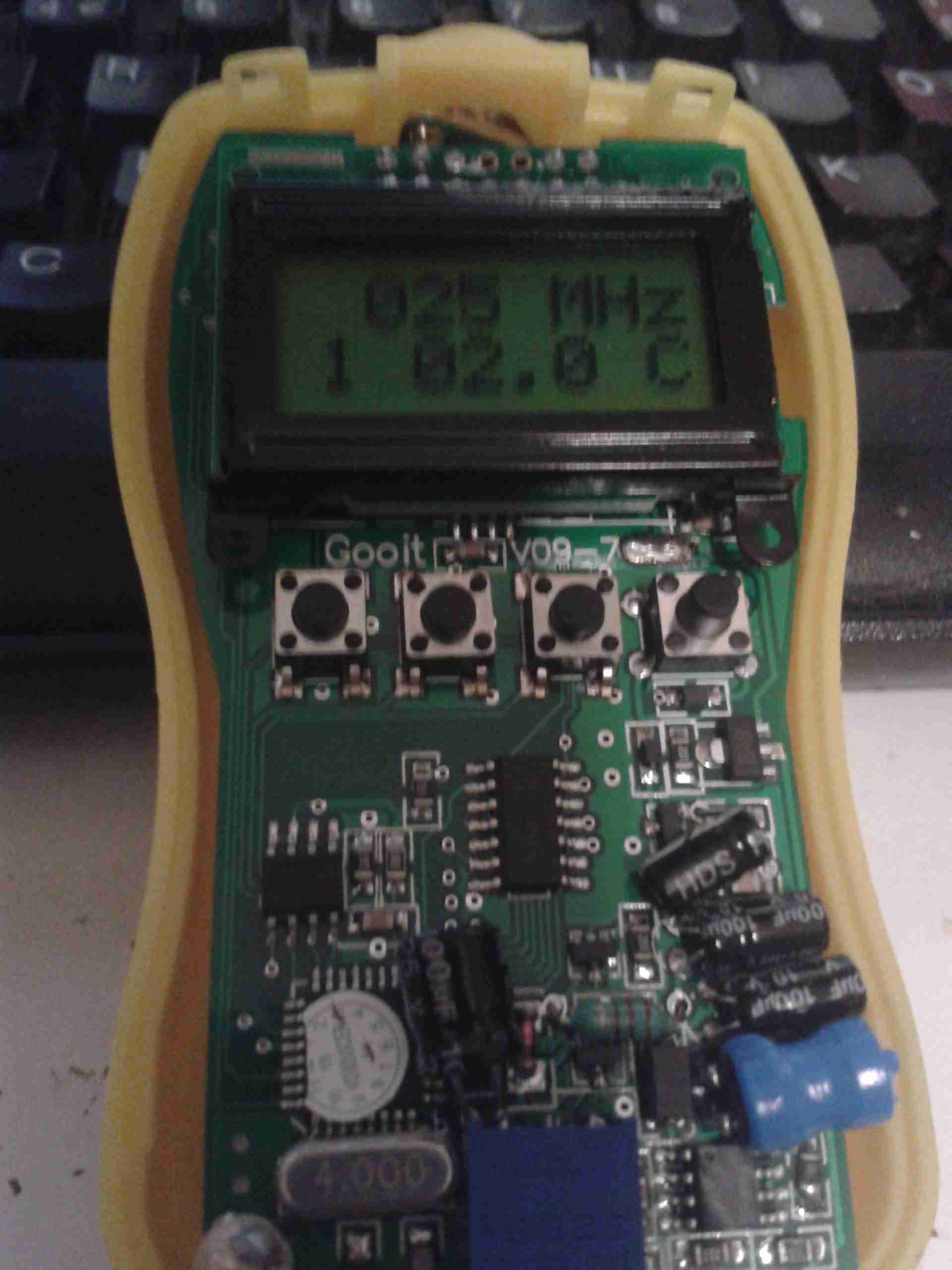
Here are the power settings as measured by my GY-561. Frequencies used are 145.500 & 433.500
Unfortunately the manual for the eBay GY561 Frequency & RF Power Meter is very badly translated, but I think I have figured out the calibration procedure, so here it goes 🙂
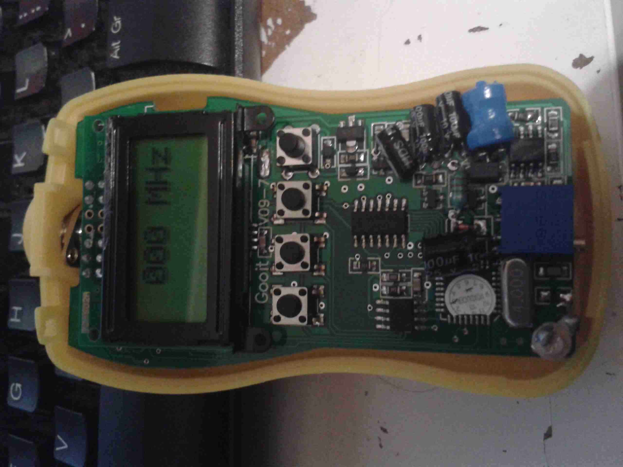
Initial Screen
On removing the front cover, which is just clipped on, there are 4 buttons. The only button that is usually available is the one on the far right, the power button.
I will term these buttons A, B, C, D, starting from the left side.
To get into the initial calibration screen, in the above image, hold button A while the power button (D) is pressed. Release the power button (D), then release button A.
The meter will show the screen above, where the frequency to calibrate can be chosen. This goes in 5MHz steps, 0-500MHz, using the B button to go down in frequency, and the C button to go up.
Once you’ve selected the frequency you wish to calibrate against, press button A, and the following screen will appear:
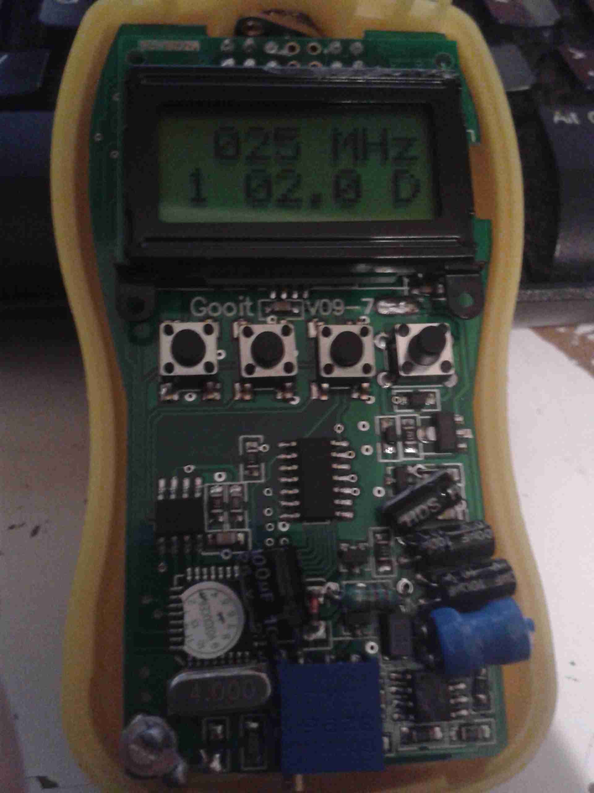
Frequency Calibration Screen
On this screen, the actual calibration can be done.
The number in the bottom left signifies the power level setting, from 1-5. The centre number is the calibration setting in Watts. The D in the bottom corner signifies that the setting is at the factory default.
Button C will cycle through the power level settings, for 2W, 5W, 10W 20W, 40W. This allows calibration at different power levels per frequency.
Once you have the frequency to calibrate, and you’ve selected the power level to calibrate at, connect a known RF power source to the input of the unit.
At this point, key the transmitter, and press button A. The display will change to the following:
Calibration Stage 2
When on this screen, you can set the power level of your RF source. Use the A key for +0.1W, the B key for +1W, and the C key for +10W.
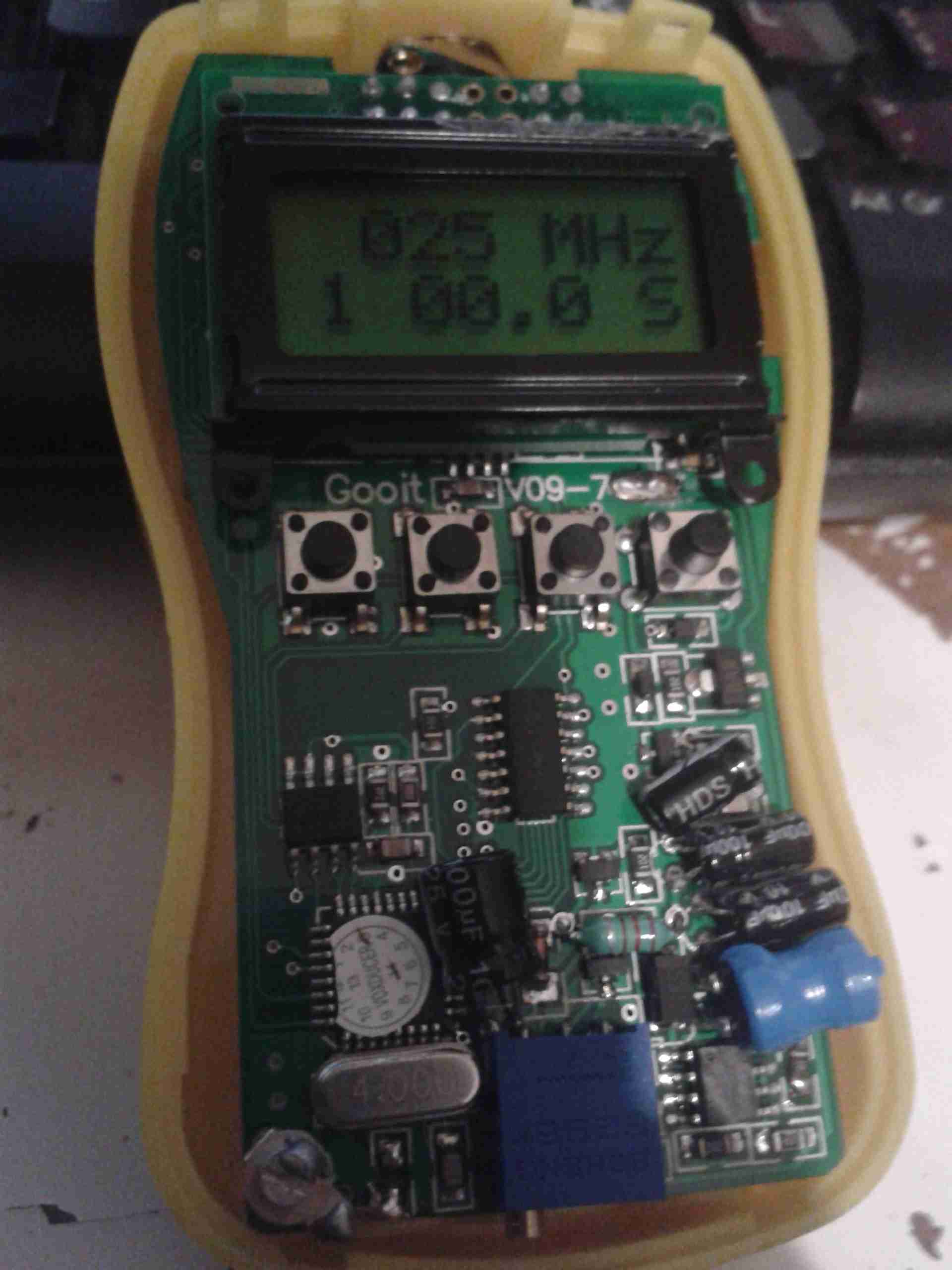
Once you’ve keyed in the power of your source, press button D to save the setting. The “S” in the bottom corner will change to a “C”, to indicate a user calibration has been entered:
Calibration Complete
If you make a mistake with entering the power level, press the “C” key to cycle up to 60W, once at this level, another press of the button will reset the reading to zero. You can then enter the power level again.
If you wish to revert a user-entered setting to the factory default, press button B on the page above. The “D” will reappear in the bottom corner to indicate the setting has been restored.
At this point you can either press button C to calibrate at another power level for this frequency, or press button D to go back to the frequency selection.
Press button D again when at the frequency selection page to turn the unit off. The unit will then power up normally next time the power button (D) is pressed.
A while ago I blogged about modifying the output voltage of some surplus Cisco switch power supplies to operate at 13.8v.
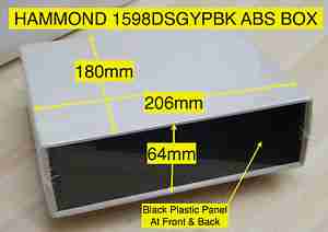
Since I was able to score a nice Hammond 1598DSGYPBK ABS project box on eBay, I’ve built one of the supplies into a nice bench unit.
Hammond ABS CaseSupply Unit
Above is the supply mounted into the box, I had to slightly trim one edge of the PCB to make everything fit, as it was just a couple of mm too wide. Luckily on the mains side of the board is some space without any copper tracks.
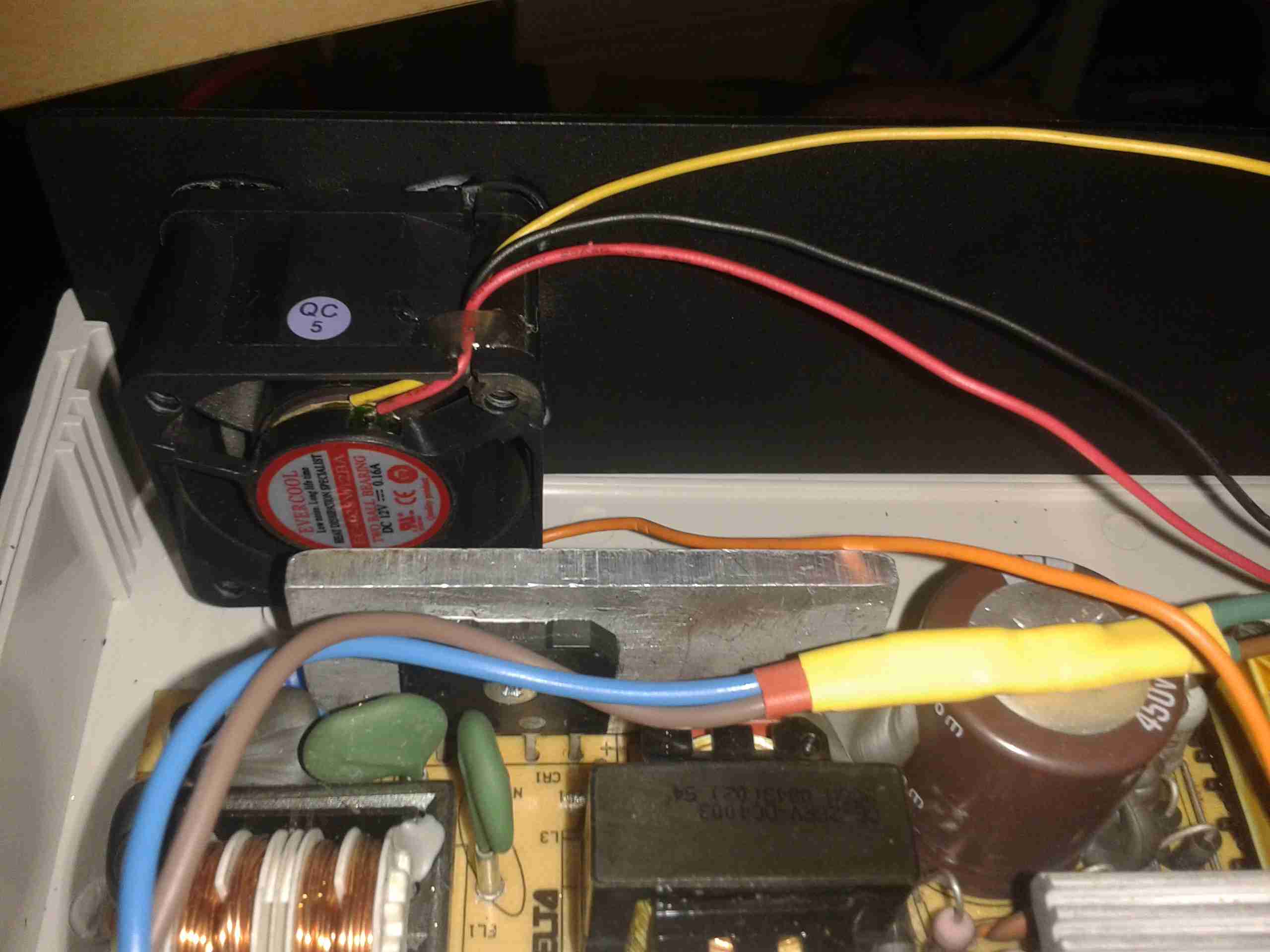
PSU Fan
These supplies are very high quality & very efficient, however they came from equipment that was force-air cooled. Running the PSU in this box with no cooling resulted in overheating. Because of this I have added a small 12v fan to move some air through the case. The unit runs much cooler now. To allow the air to flow straight through the case, I drilled a row of holes under the front edge as vents.
Output Side
Here is the output side of the supply, it uses standard banana jacks for the terminals. I have used crimp terminals here, but they are soldered on instead of crimped to allow for higher current draw. The negative return side of the output is mains earth referenced.
I have tried to measure output ripple on this supply, but with my 10X scope probe, and the scope set to 5mV/Div, the trace barely moves. The output is a very nice & stable DC.
This supply is now running my main radio in the shack, and is small enough to be easily portable when I move my station.
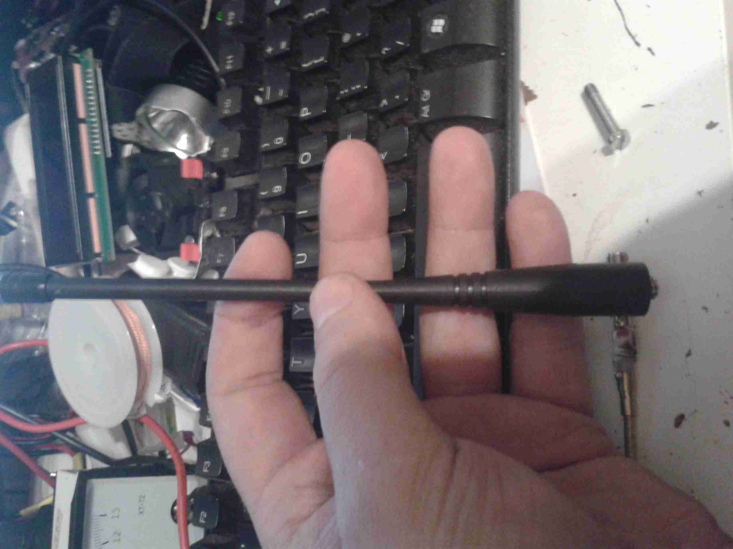
Recently I’ve noticed my usual mobile rig, the Baofeng UV-5R, has had very poor receive, and non-existent transmit.
I did a power test on the radio, and confirmed it was still outputting it’s rated RF power. Trying another antenna proved that the radio was fine.
Time to tear down the antenna & see if it can be fixed!
Stock Antenna
Here’s the antenna, just the factory rubber duckie. As with all these antennas, they’re a compromise between size & their efficiency.
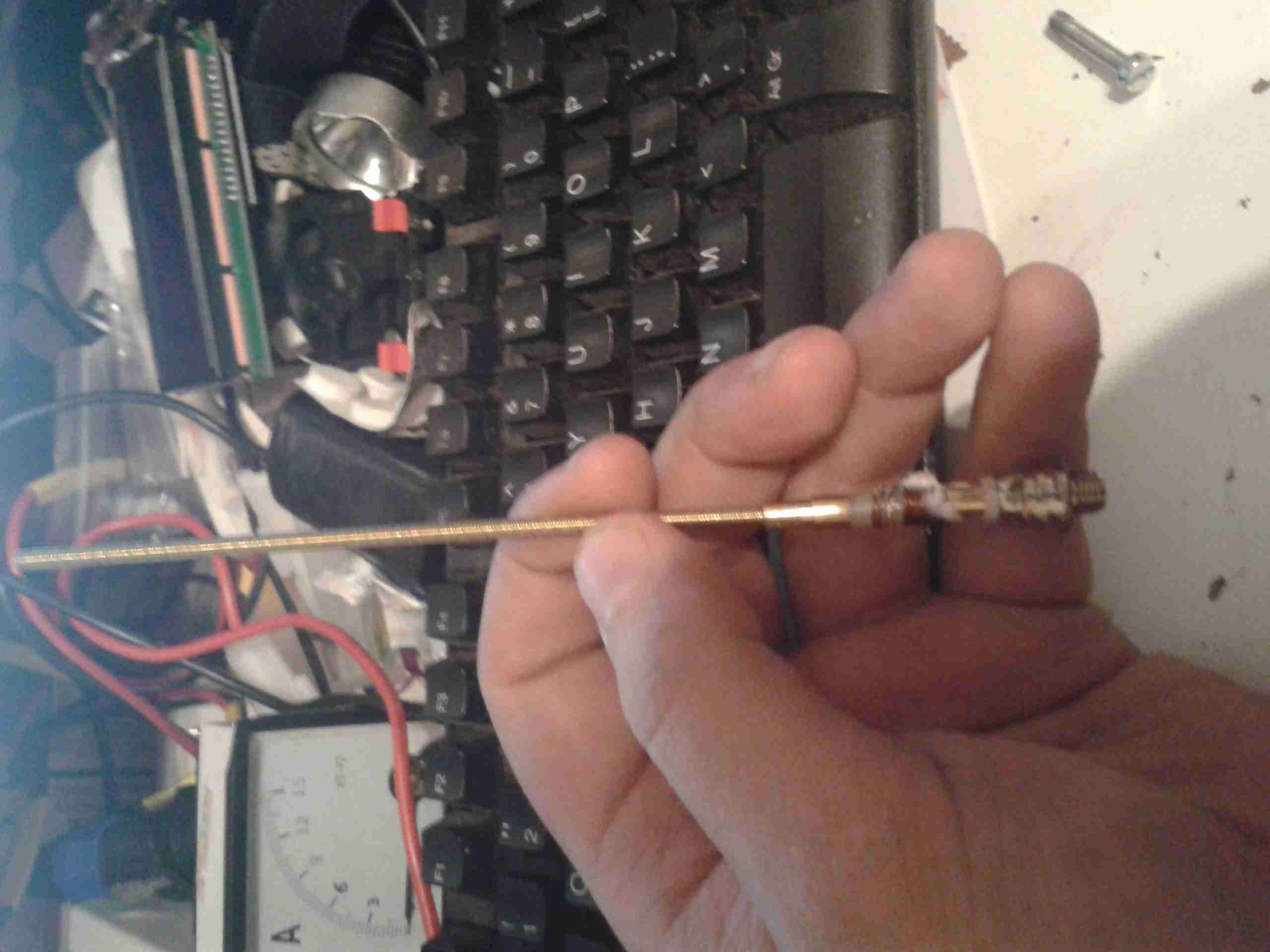
Naked Antenna!
Giving a gentle pull to the antenna sheath while it’s attached to the radio allows it to come apart. The quality actually doesn’t look to bad. It’s very similar in construction to my Diamond X-30, just on a much smaller scale.
At the bottom of the antenna is the matching network, an inductor & ceramic disc capacitor. Here lies the problem with this antenna.
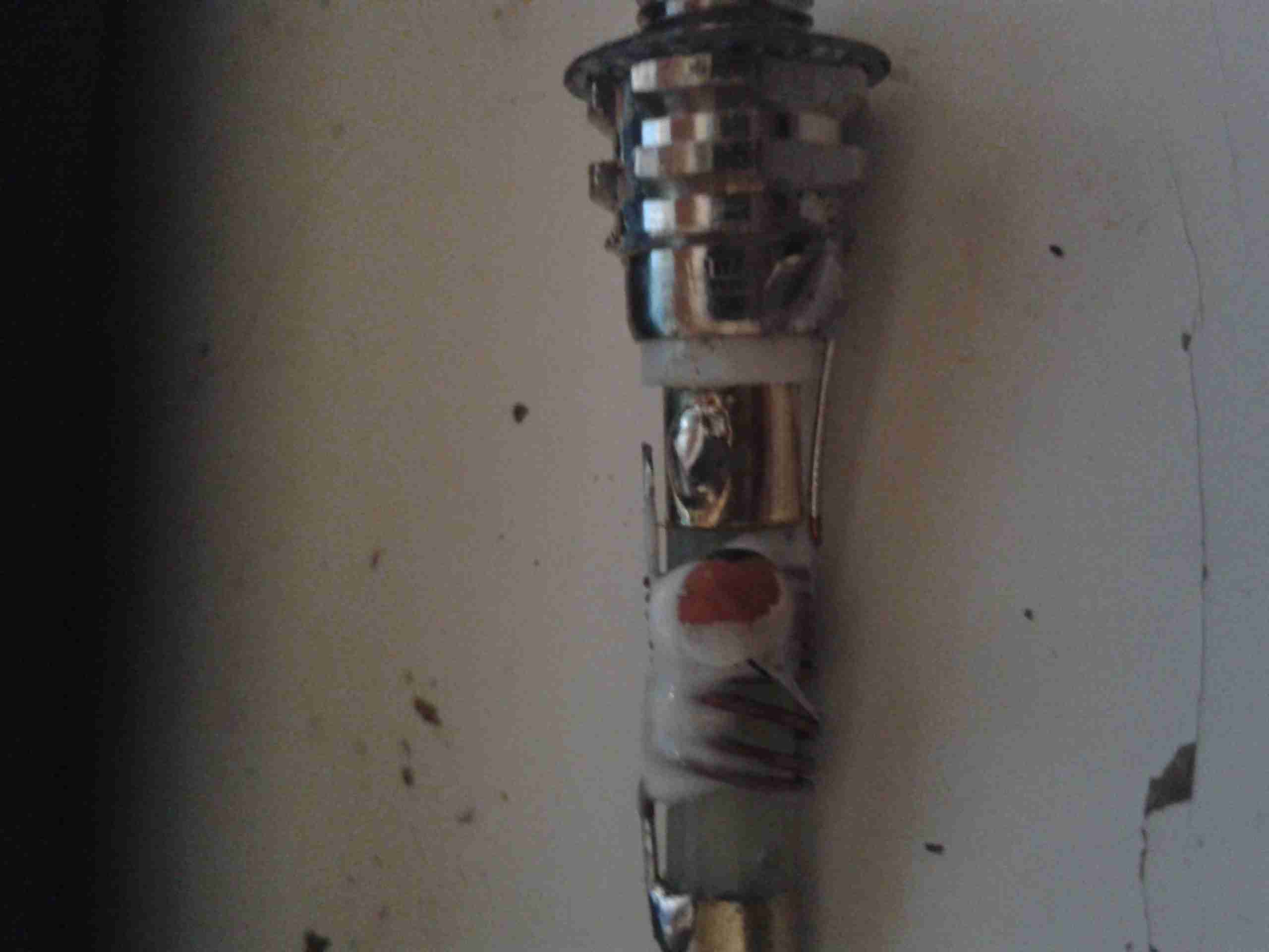
Dry Joint
Here where the capacitor joins onto the feedpoint from the SMA connector, the solder joint has come away. This was a very poor joint to start with, and the solder hadn’t wetted the capacitor lead at all
After cleaning the joint, and applying some flux, a new joint was easily made with some Real Solder.
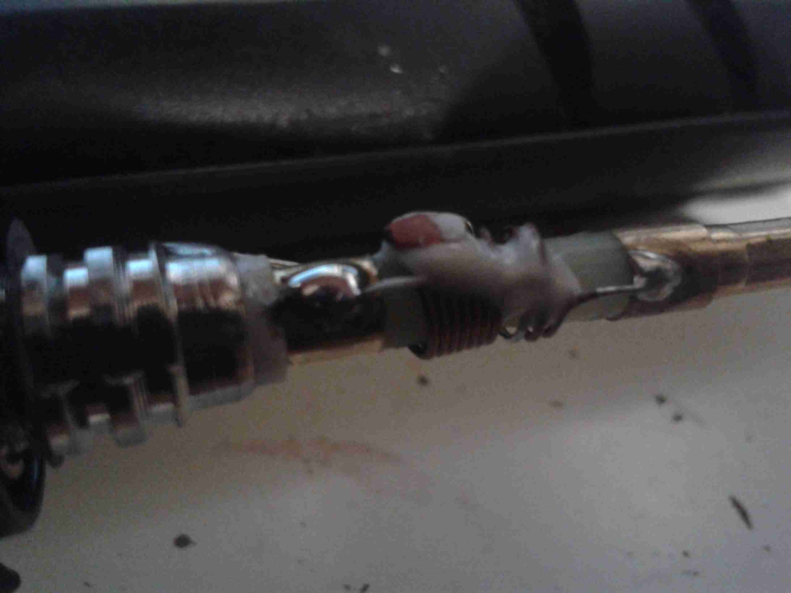
Repaired Joint
Here’s the joint freshly repaired, the antenna is now back to full working order. It even seems to work better than the others I have 🙂
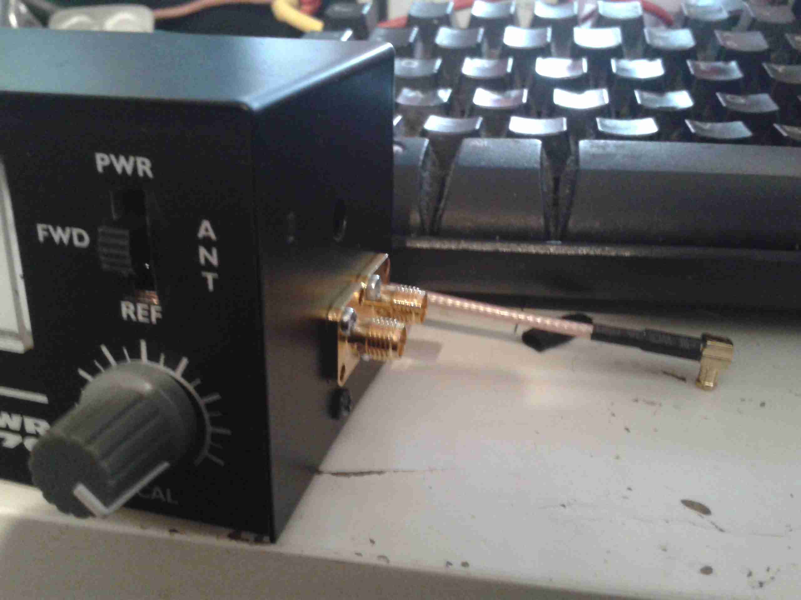
Now the final bits have arrived for the SWR Meter module, I can do the final assembly.
SMA Connectors
Here the SMA connectors are installed on the side of the eBay meter, for forward & reverse power tap.
These are simply tee’d off the wiring inside the meter where it connects to the switch.
Uncalibrated
The meter is connected to the module via a pair of RG58 SMA leads, above is a readout before calibration, using one of my Baofeng UV-5Rs.
I’m using my GY561 eBay Power Meter as a calibration source, and as this isn’t perfect, the readings will be slightly off. If I can get my hands on an accurate power meter & dummy load I can always recalibrate.
Tools are only as accurate as the standard they were calibrated from!
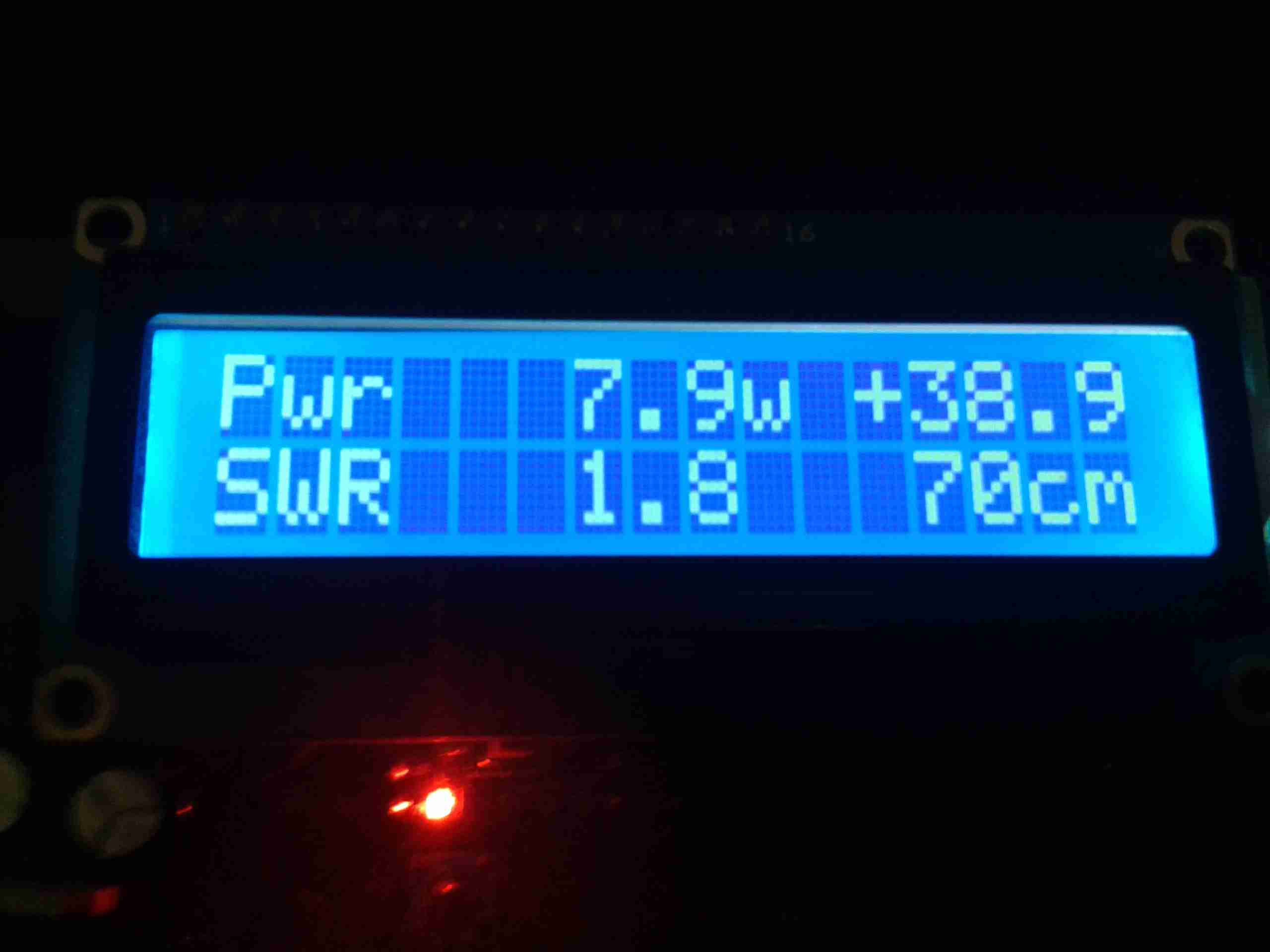
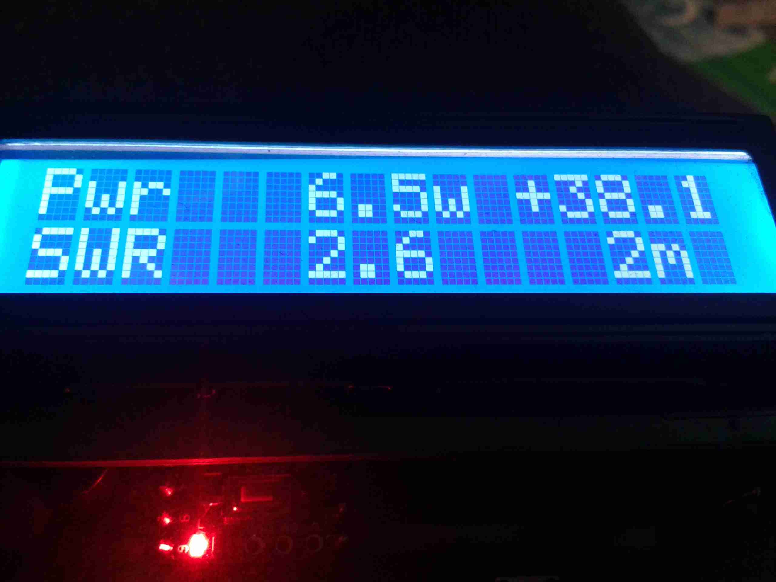
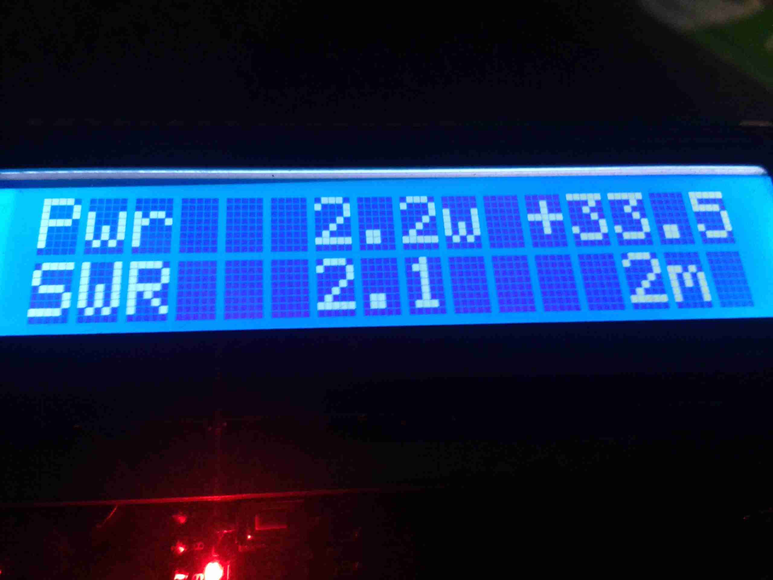
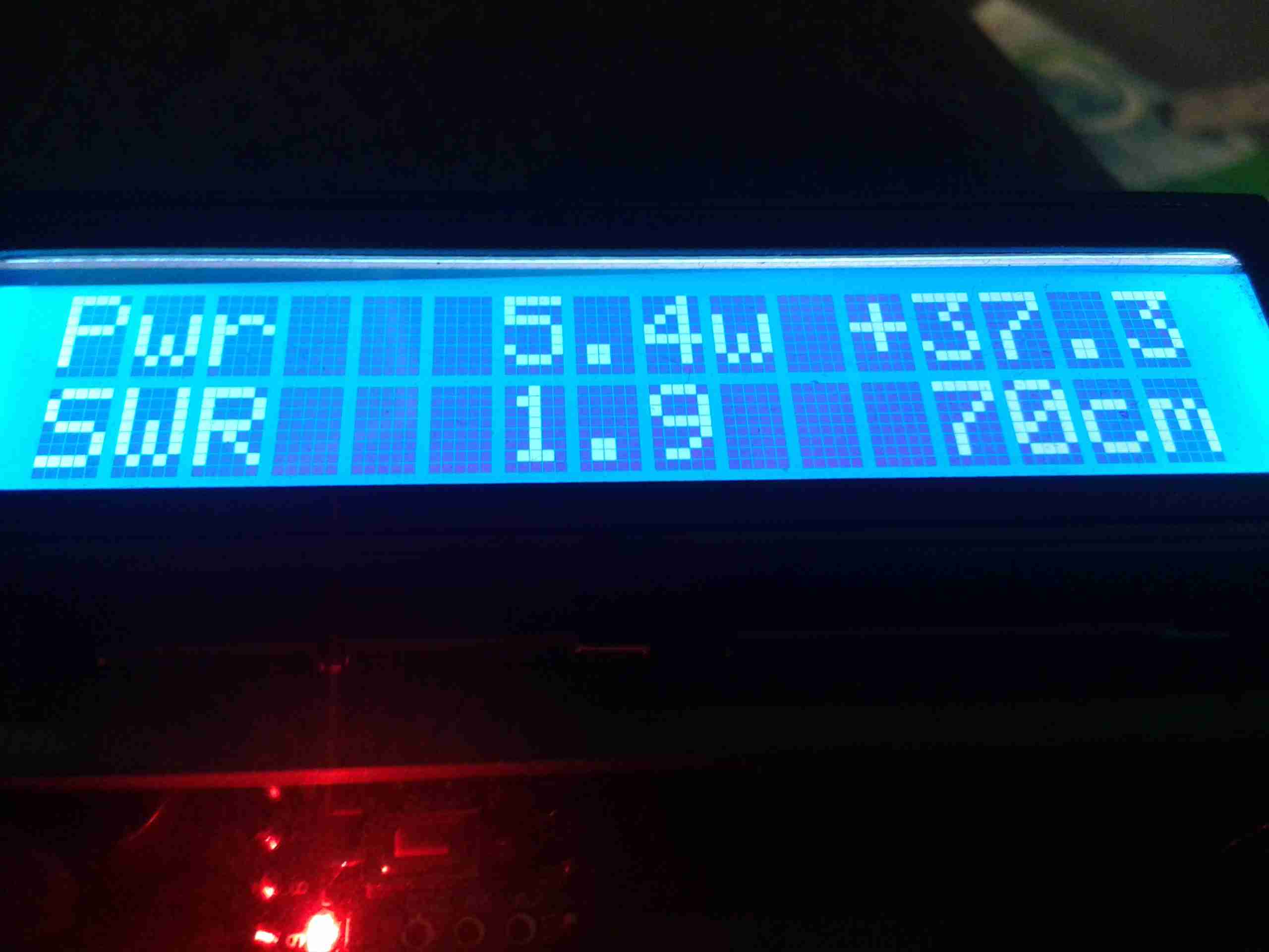
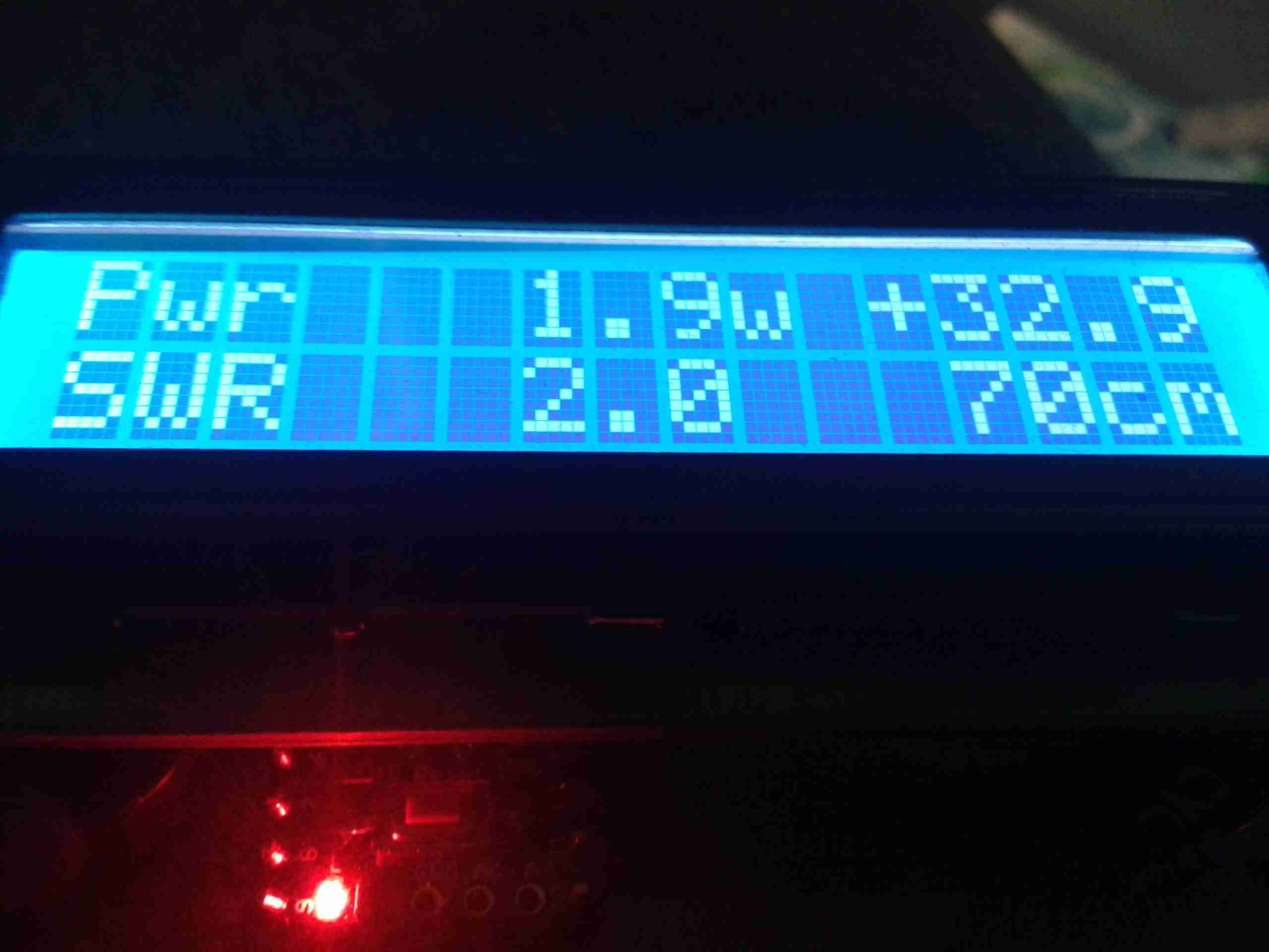
After calibration, here’s the readings on 2m & 70cm. These readings coincide nicely with the readings the GY561 produce, to within a couple tenths of a watt. SWR is more than 1:1 as the dummy load in the GY561 isn’t exactly 50Ω.
High Power VHFLow Power VHFHigh Power UHFLow Power UHF
Shortly I’ll calibrate against 6m & 10m so I can use it on every band I have access to 🙂
Here’s some audio from last night on PMR, the regular group seem to be getting a little hacked off 🙂
(I do love the way these guys go on about abuse on the band when they’re transmitting on enough power to rival the BBC, they mustn’t know that PMR446 is limited to 500mW, the Baofengs they’re using only go as low as 1W, usually more when measured).
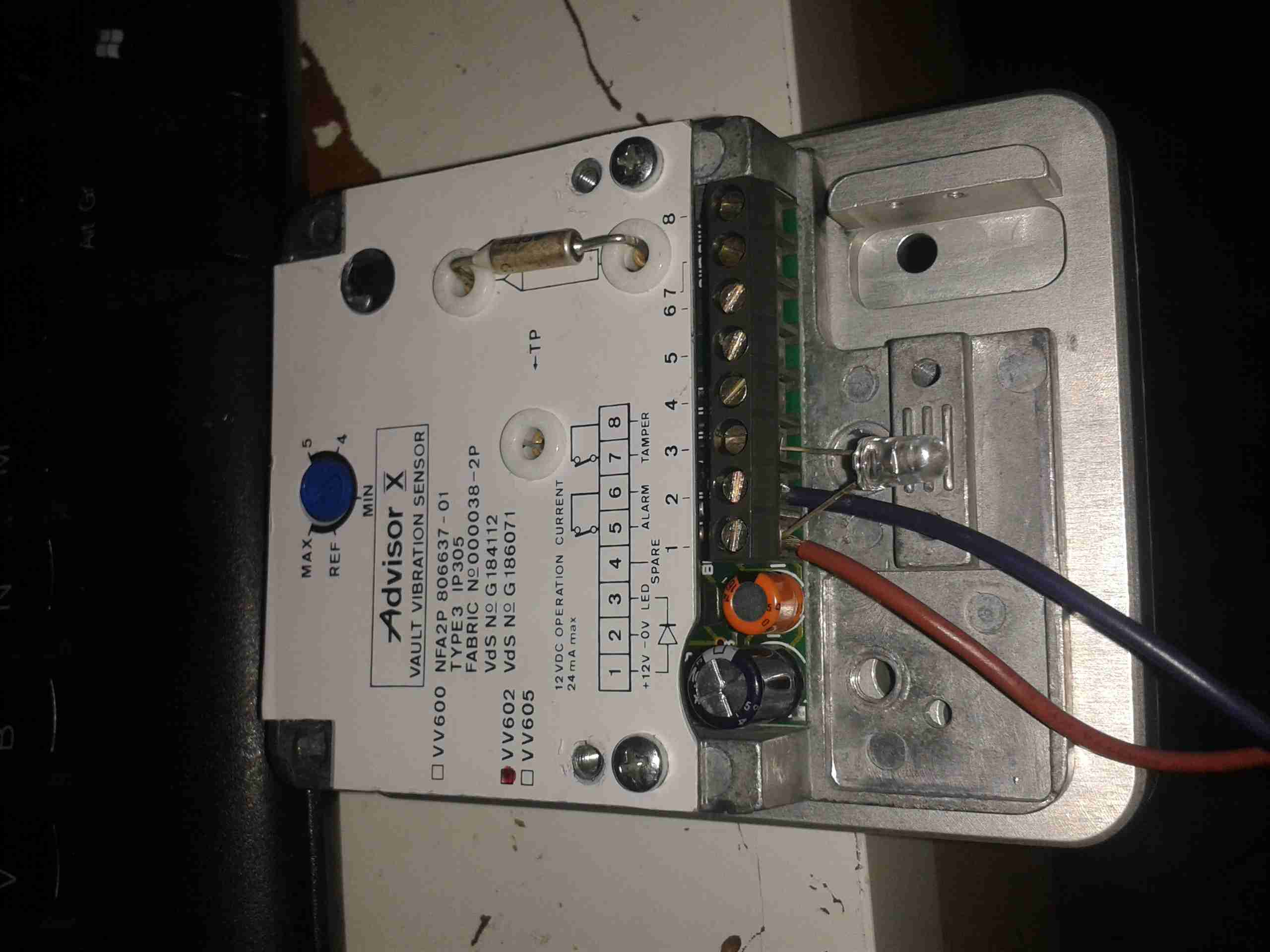
Here’s a rather unique device for protecting safes & vaults from attack by thefts.
It’s an Aritech VV602 seismic detector, based on piezoelectric sensors. Not surprisingly, this unit is covered in tamper sensors as well. There are several different sensor types in use:
Piezoelectric vibration sensing
Thermal sensing
Magnetic sensing
Manual Tamper Switches
Sensor Unit
Above is the main unit, with the thermal sensor. This is just a thermal fuse, very commonly used in everything from room heaters to hairdryers. This one triggers at 84°C. The adjustment pot is also visible here.
Mounting Plate
Above is the magnetic mounting plate used to attach the device to the safe. These units are apparently mounted over the keyhole of the safe to protect the lock, so they need to be easily removable to access the safe. This is a very strong magnet & it isn’t possible to pull it from a metal object without triggering the sensor.
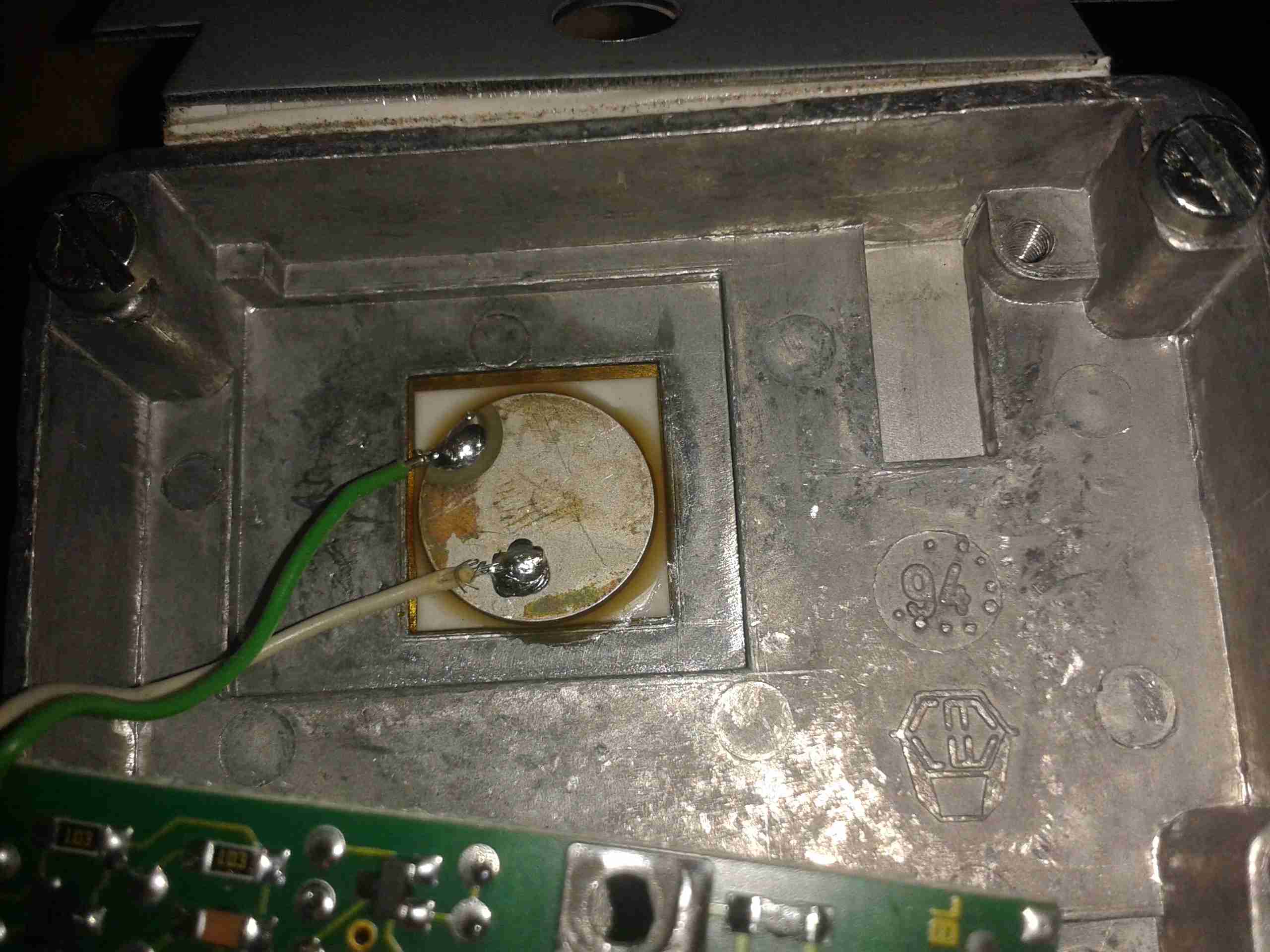
Piezo Sensor
Above is the piezo vibration sensor, bonded to the backplate. When the unit receives vibration or shock, this transducer generates a voltage, which is fed to the control logic below.
Control Logic
Here’s the reverse of the main PCB with the control logic ICs. These are basic logic gates, with a couple of comparators. One of the tamper switches is in the bottom left corner.
Main PCB
Main PCB with the connection terminals. Another tamper switch is in the top left corner, the solid-state relay is under the shield, next to the magnetic tamper switch. (Reed switch).
Some adjustment is provided for sensitivity. I’ve not found much of a difference in sensitivity though when it’s set to different levels.
Reed Tamper
Magnetic reed switch tamper on the right. Main output solid-state relay on the left under the shield.
This unit was given to me after it apparently went faulty. But on applying power it seems to work fine. Must be those experts again 😉
Following on from the earlier power tests on my Baofeng HTs, here’s the readings from the Wouxun KG-UV950P. Power is a little lower than specified, but this is probably due to the supply voltage being a bit less than 13.8v. These readings were taken at a supply voltage of 12.88v.
The same frequencies were used, 145.500 & 433.500 for the VHF/UHF tests. For the 6/10m tests 27MHz & 50MHz were used.
The power meter was connected with 1 metre of RG58 dual-screened cable with N-type connectors.
Recently I decommissioned some networking equipment, and discovered the power supplies in some switches were single rail 12v types, with a rather high power rating. I figured these would be very good for powering my Ham radio gear.
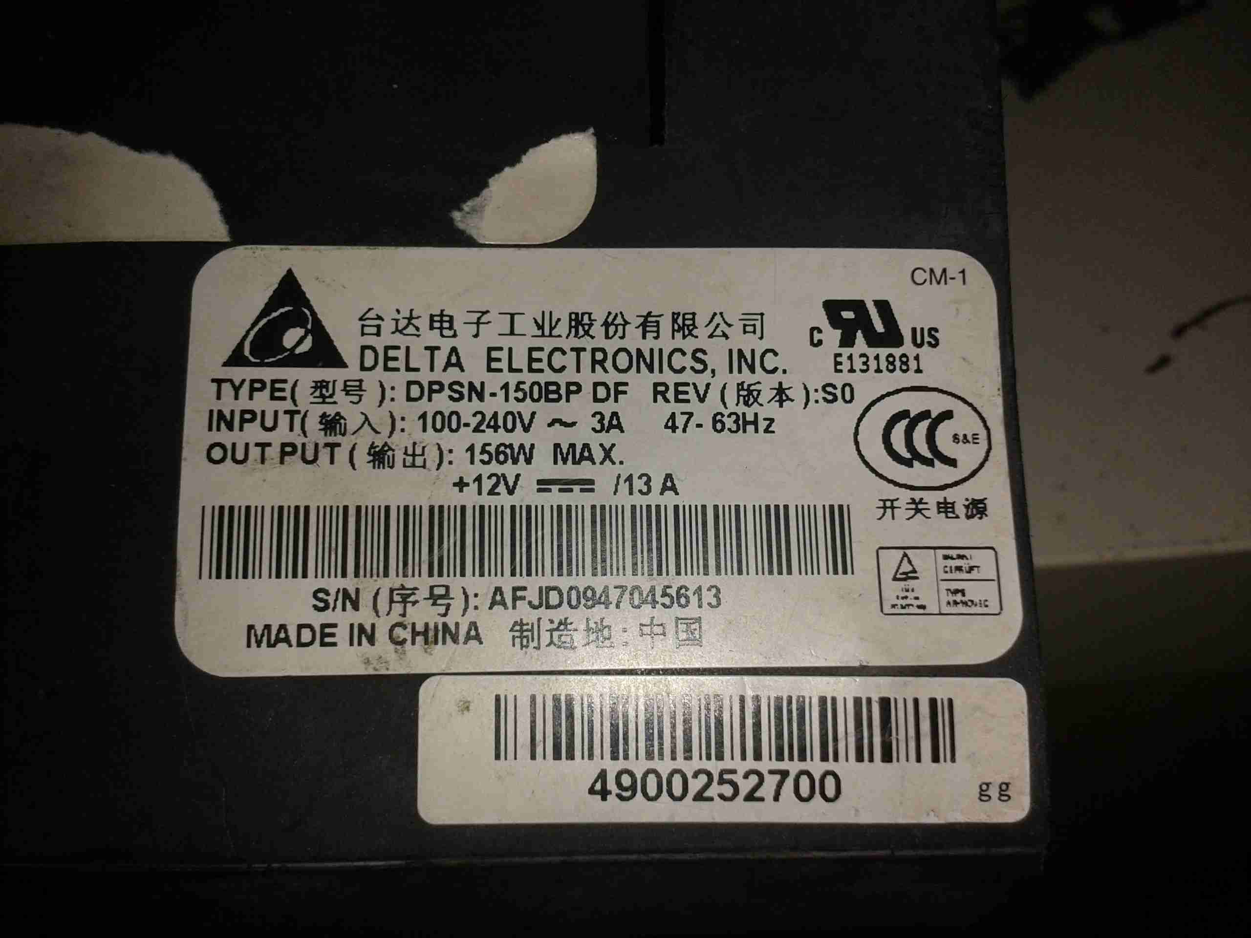
They’re high quality Delta Electronics DPSN-150BP units, rated at a maximum power output of 156W.
Label
These supplies have an adjustment pot for the output voltage regulation, but unfortunately it just didn’t have quite enough range to get from 12.0v to 13.8v. The highest they would go was ~13.04v.
After taking a look at the regulator circuit, I discovered I could further adjust the output voltage by changing a single resistor to a slightly lower value.
Firstly though, a little background on how switched mode power supplies operate & regulate their output voltage.
SMPS
Here’s the supply. It’s mostly heatsink, to cool the large power switching transistors.
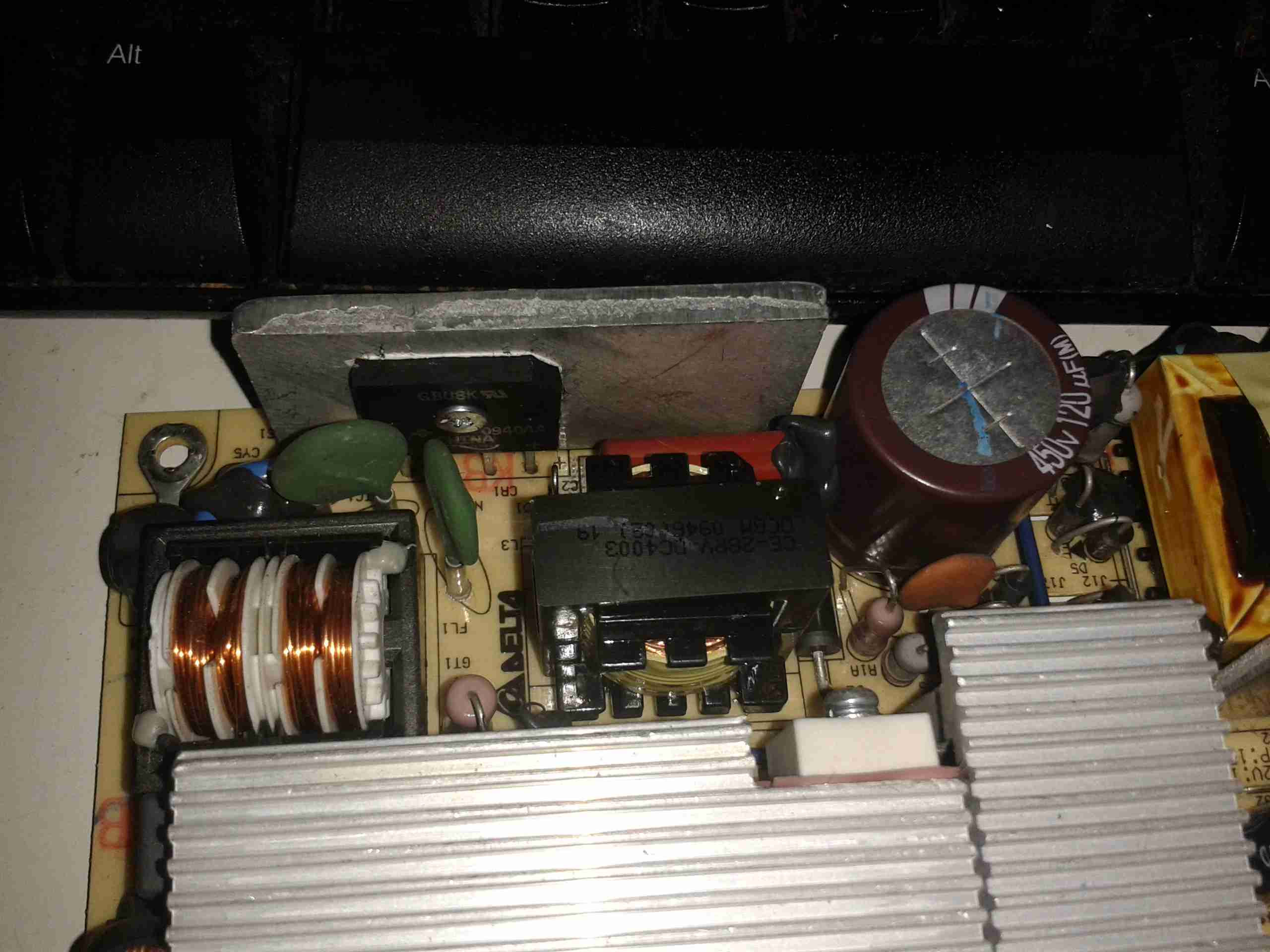
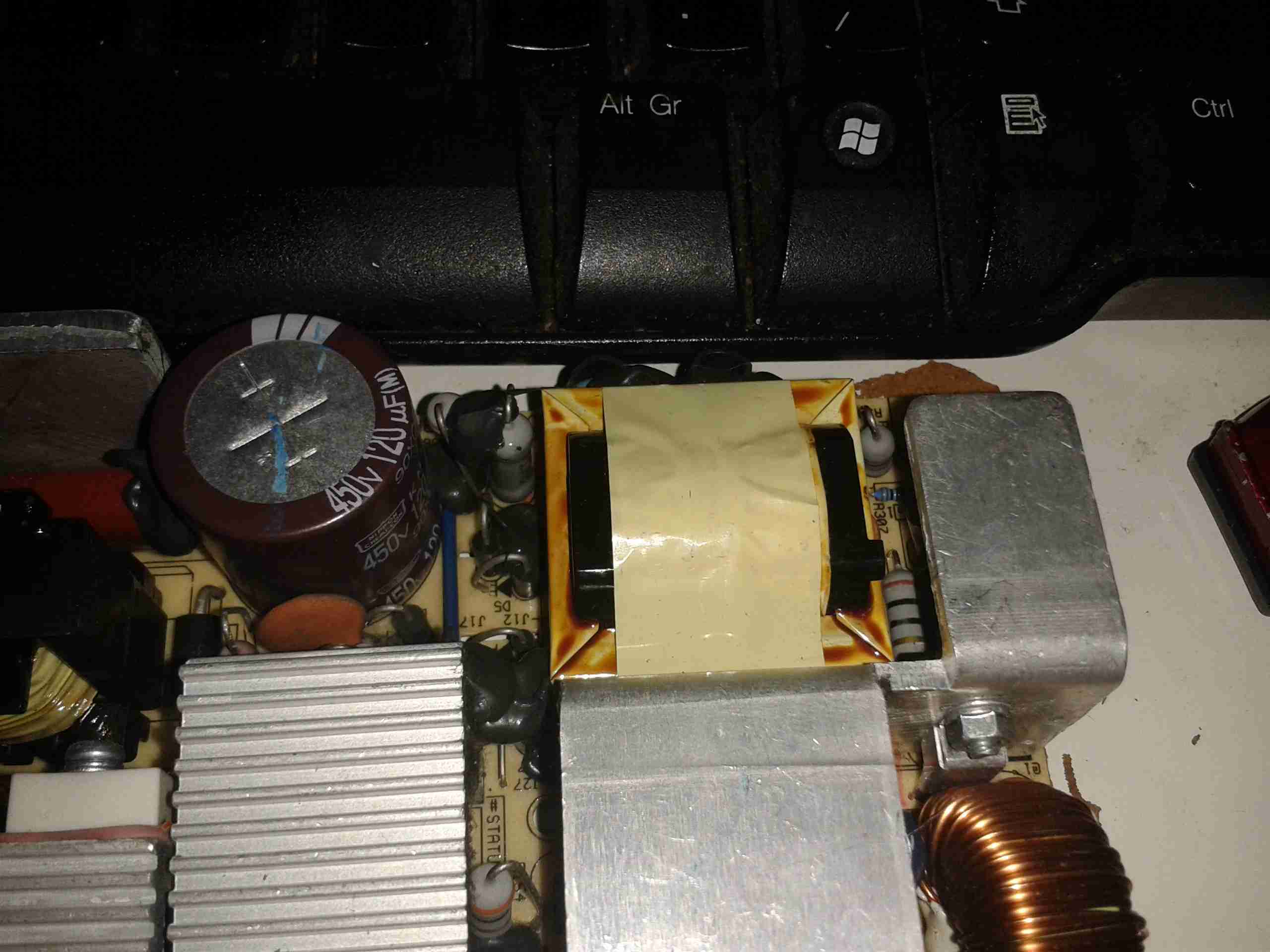
The first thing a SMPS does, is to rectify the incoming mains AC with a bridge rectifier. This is then smoothed by a large electrolytic capacitor, to provide a main DC rail of +340v DC (when on a 240v AC supply).
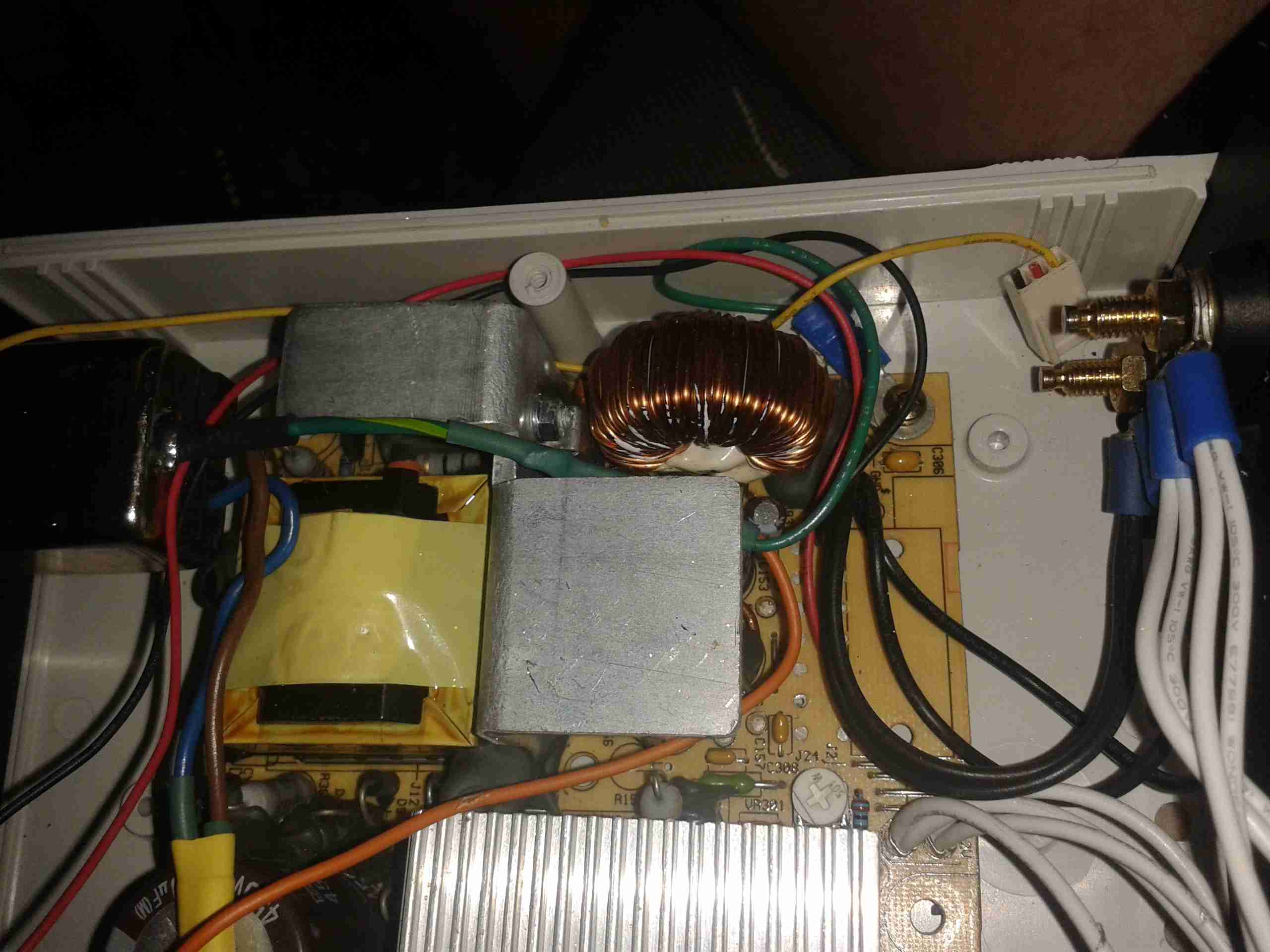
Mains Input
Above is the mains input section of the PSU, with a large common-mode choke on the left, bridge rectifier in the centre, and the large filter capacitor on the right. These can store a lot of energy when disconnected from the mains, and while they should have a discharge resistor fitted to safely drain the stored energy, they aren’t to be relied on for safety!
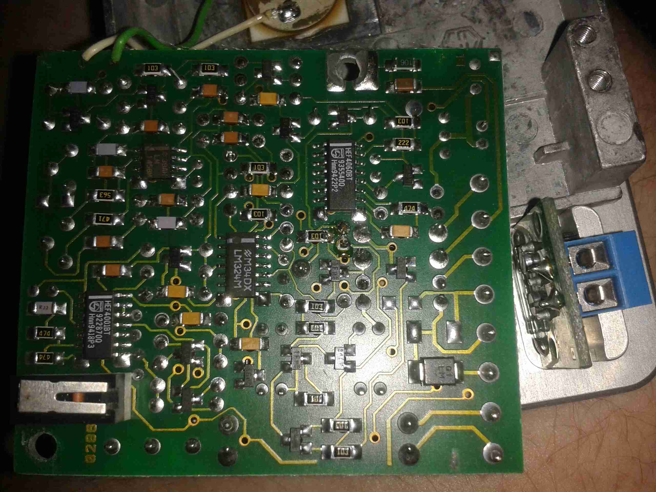
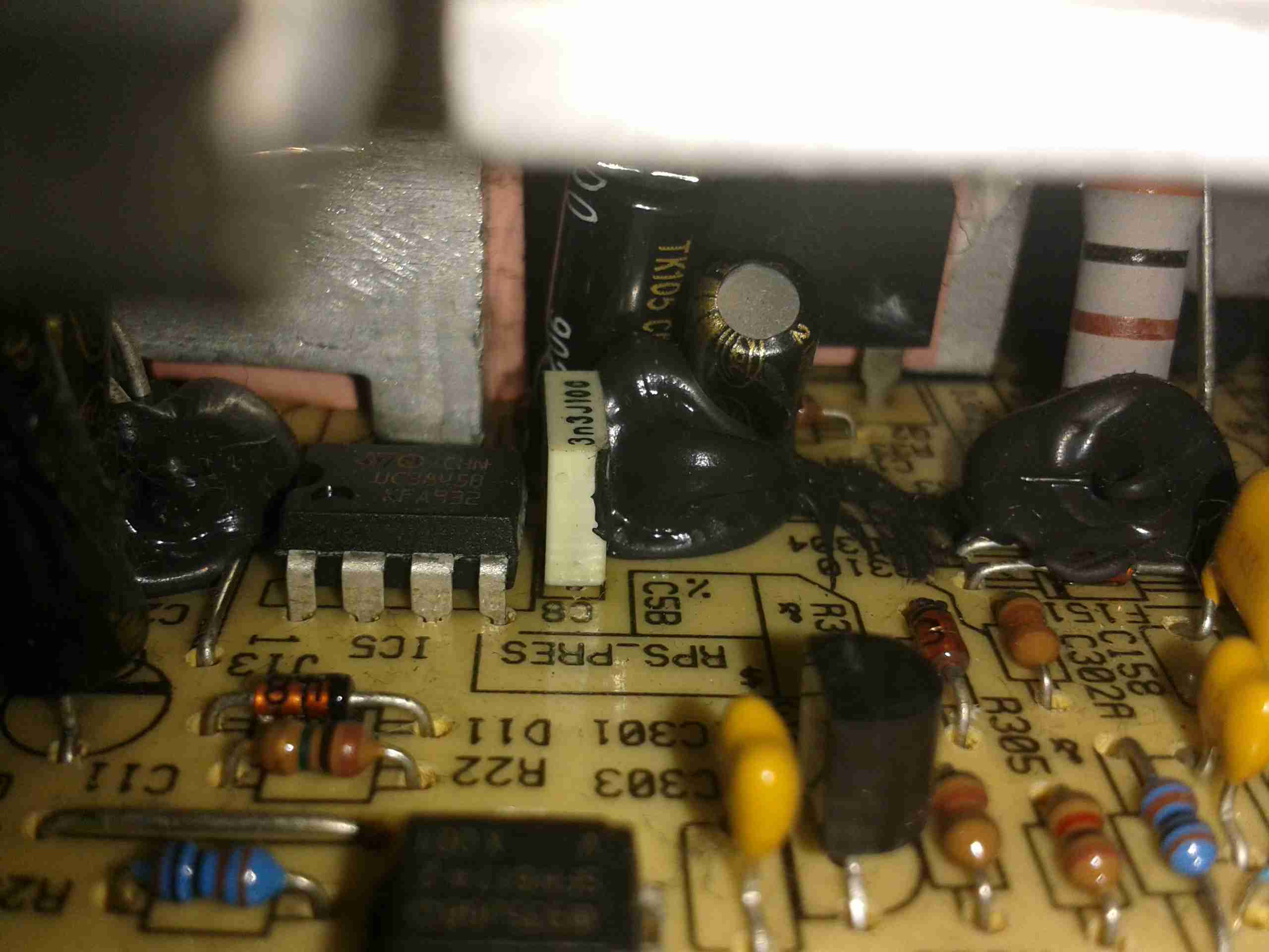
Once the supply has it’s main high voltage DC rail, this is switched into the main transformer by a pair of very large transistors – these are hidden from view on the large silver heatsinks at the bottom of the image. These transistors are themselves driven with a control IC, in the case of this supply, it’s a UC3844B. This IC is hidden under the large heatsink, but is just visible in the below photo. (IC5).
Control ICMain Switching Transformer
Here’s the main switching transformer, these can be much smaller than a conventional transformer due to the high frequencies used. This supply operates at 500kHz.
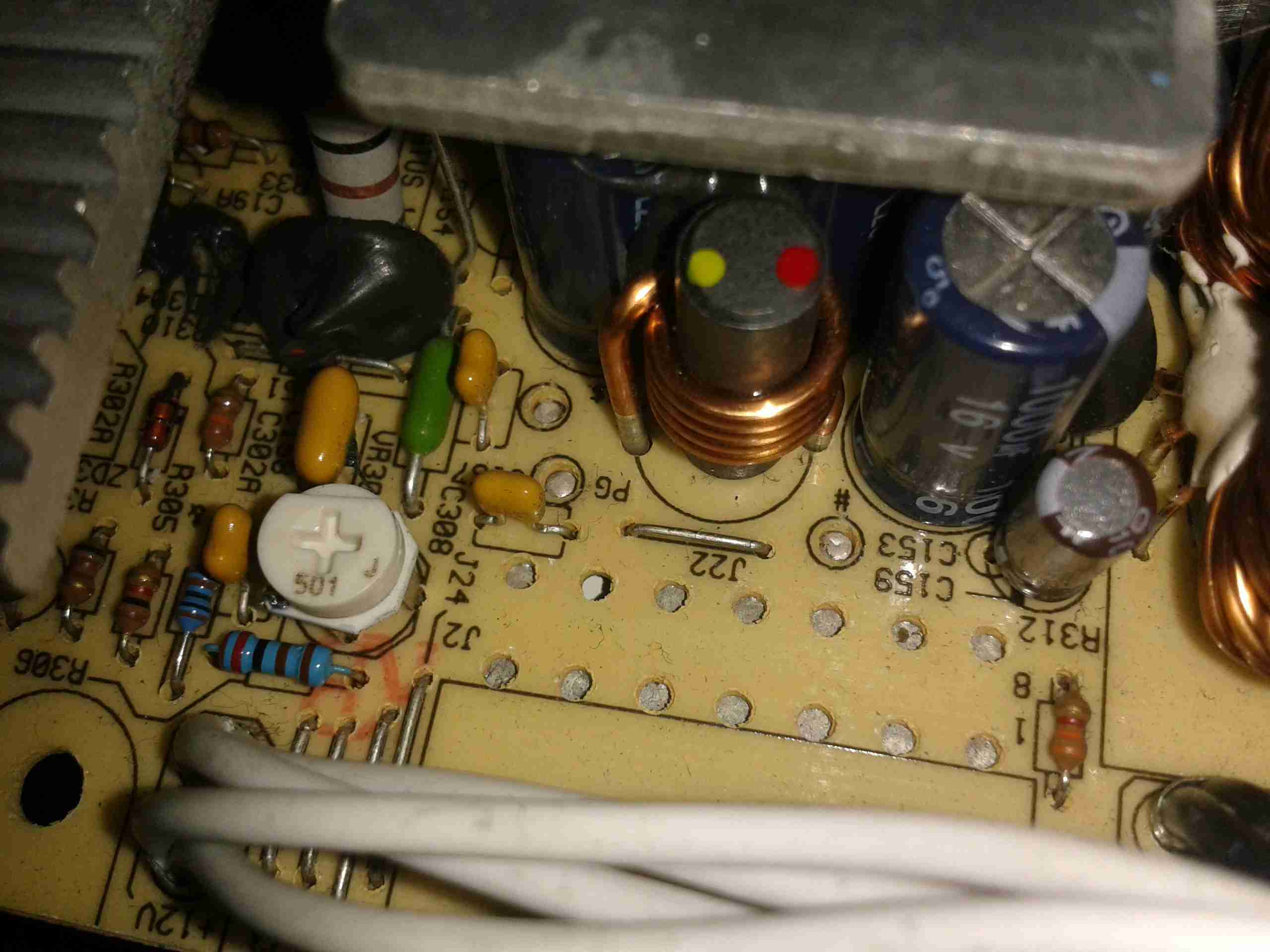
After the main transformer, the output is rectified by a pair of Schottky diodes, which are attached to the smaller heatsink visible below the transformer, before being fed through a large toroidal inductor & the output filter capacitors.
All this filtering on both the input & the output is required to stop these supplies from radiating their operating frequency as RF – a lot of cheap Chinese switching supplies forego this filtering & as a result are extremely noisy.
After all this filtering the DC appears at the output as usable power.
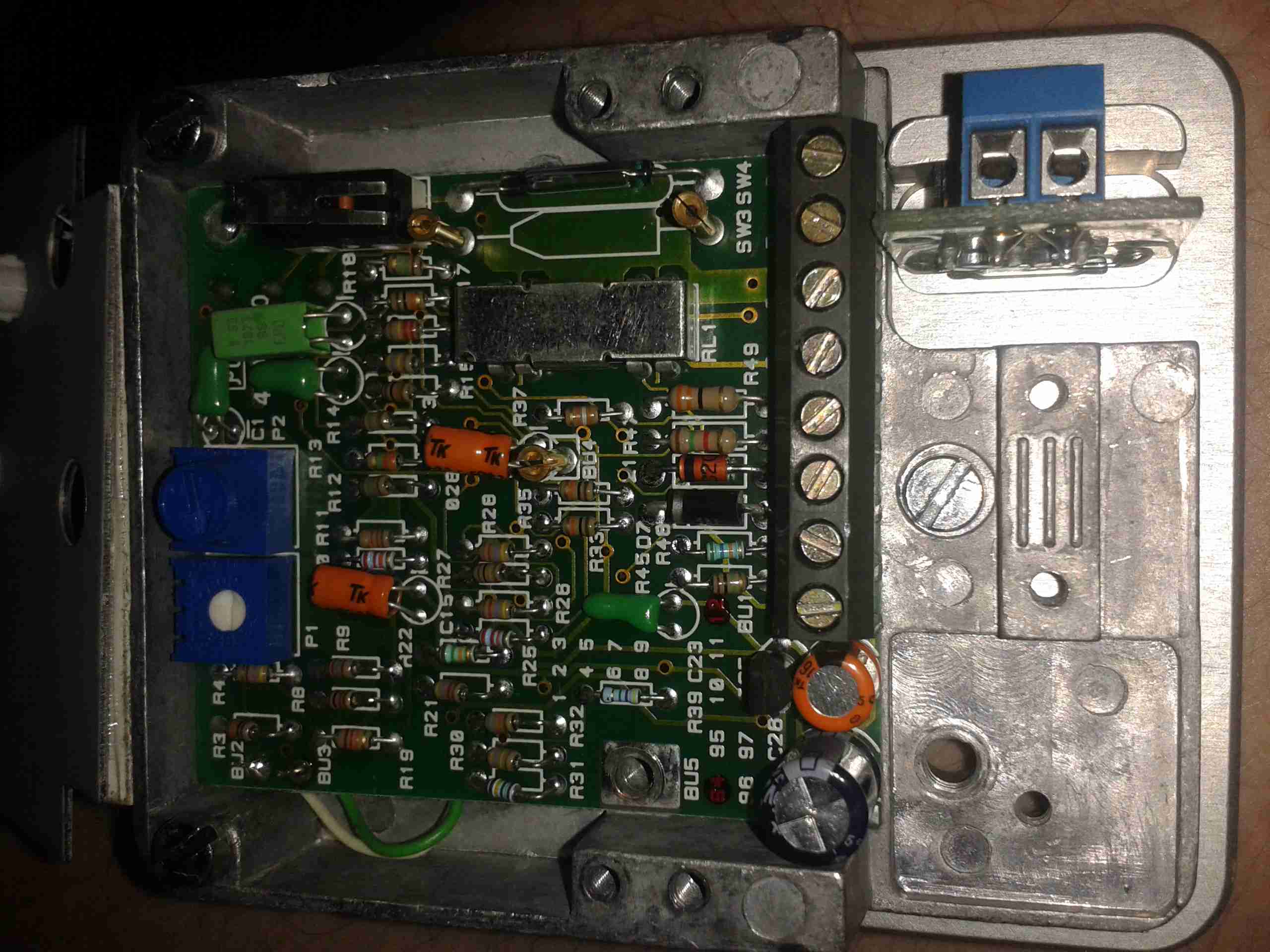
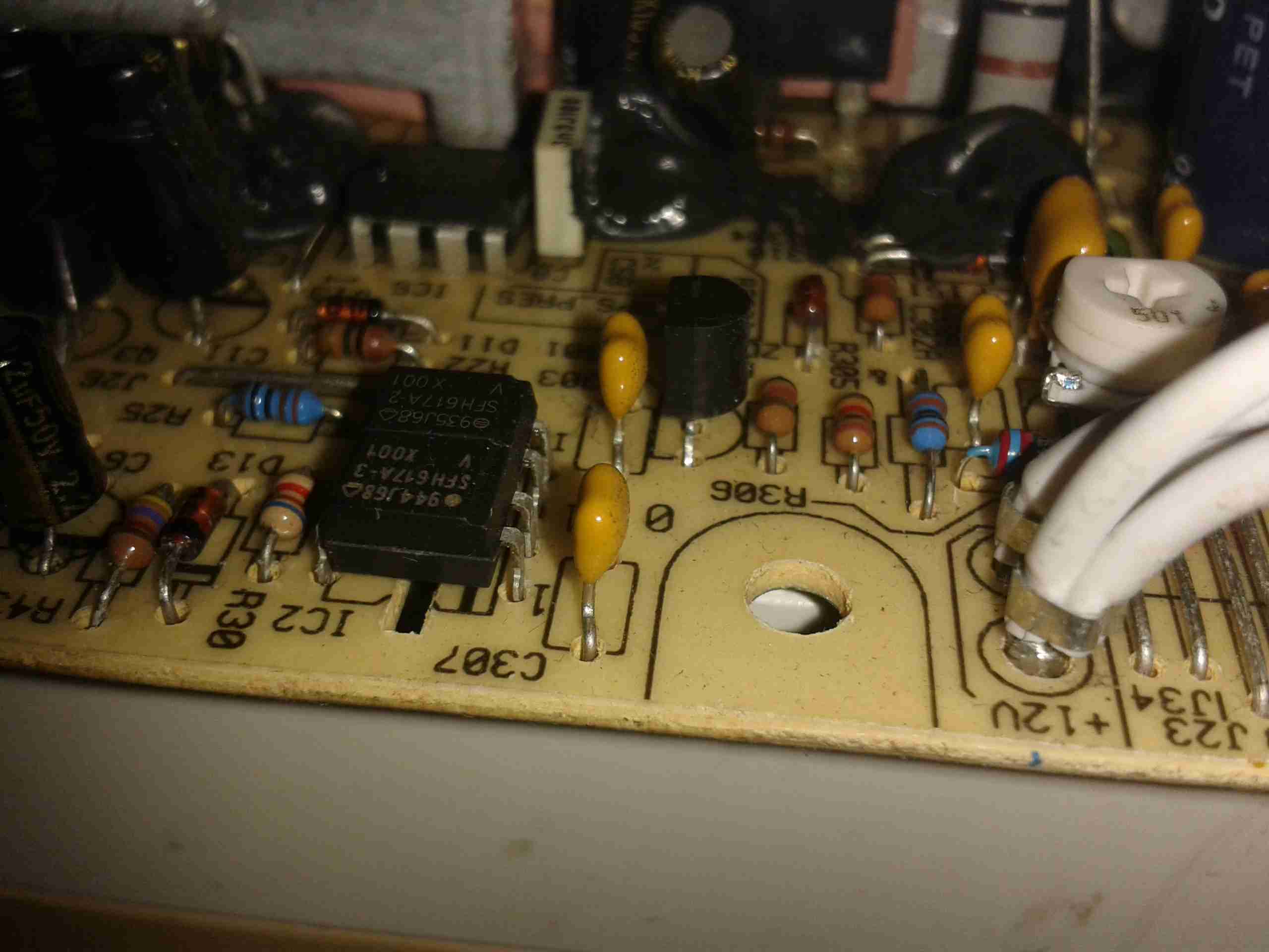
Getting back to regulation, these supplies read the voltage with a resistor divider & feed it back to the mains side control IC, through an opto-isolator. (Below).
Feedback Loop
The opto isolators are the black devices at the front with 4 pins.
Regulator Adjustment
For a more in-depth look at the inner workings of SMPS units, there’s a good article over on Hardware Secrets.
My modification is simple. Replacing R306 (just below the white potentiometer in the photo), with a slightly smaller resistor value, of 2.2KΩ down from 2.37KΩ, allows the voltage to be pulled lower on the regulator. This fools the unit into applying more drive to the main transformer, and the output voltage rises.
It’s important to note that making too drastic a change to these supplies is likely to result in the output filter capacitors turning into grenades due to overvoltage. The very small change in value only allows the voltage to rise to 13.95v max on the adjuster. This is well within the rating of 16v on the output caps.
Now the voltage has been sucessfully modified, a new case is on the way to shield fingers from the mains. With the addition of a couple of panel meters & output terminals, these supplies will make great additions to my shack.
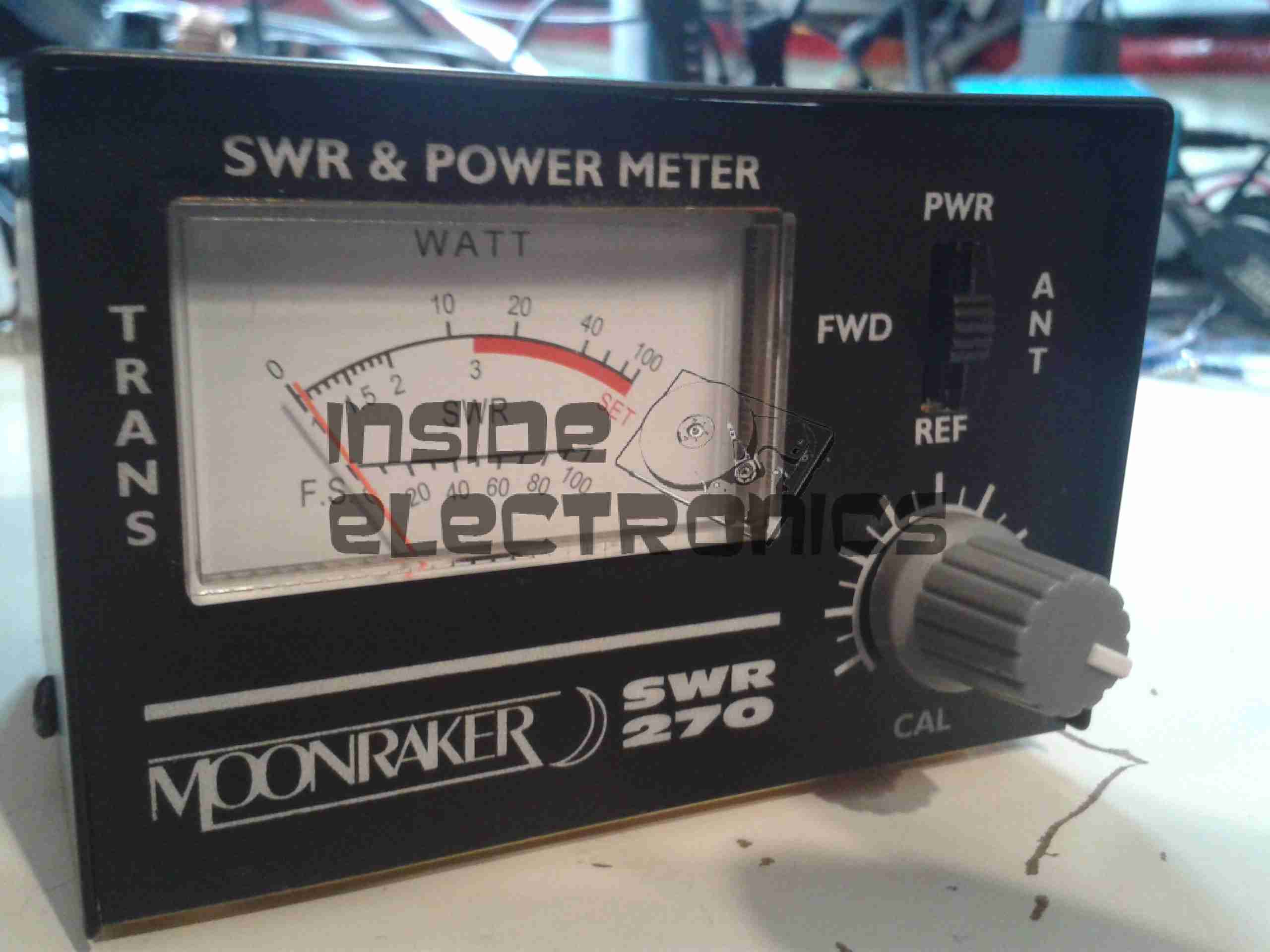
As I’m building up my radio shack, I figured an SWR meter would be a handy addition to my arsenal. This is a cheap Moonraker brand meter, which also will measure RF power. Above the front of the meter is shown, with the moving coil meter movement on the left, calibration adjustment on the right & the forward/reverse power switch.
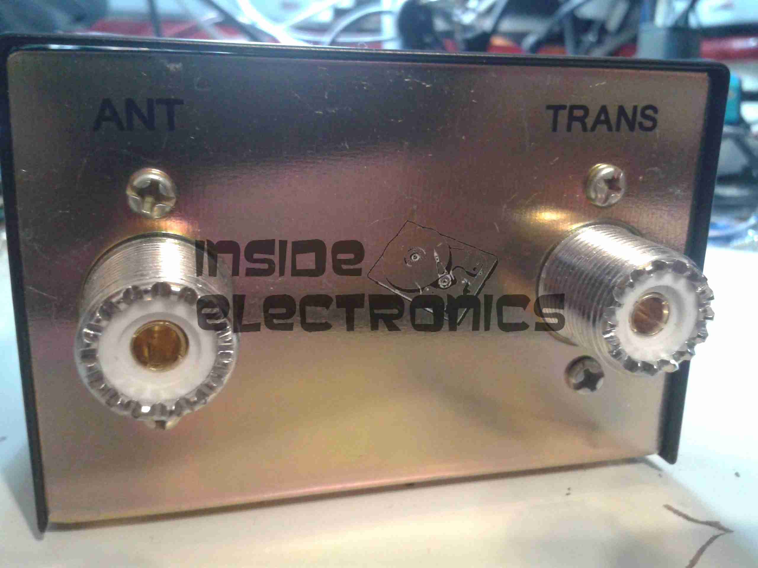
Meter Rear
For connections, standard SO-259 jacks are provided. The casing is sturdy 1mm steel. This is good, considering it’ll probably take a beating in my portable radio bag.
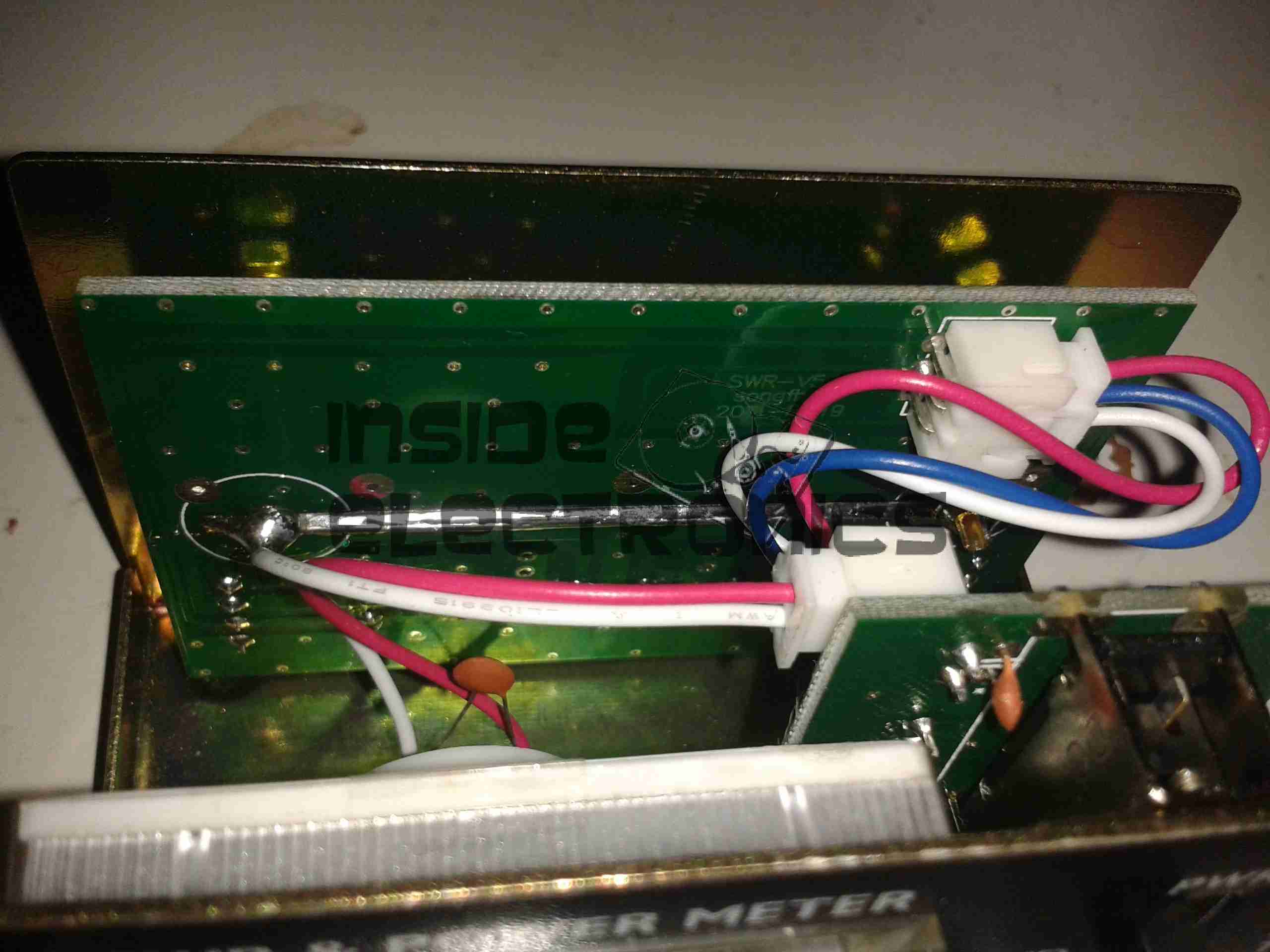
Directional Coupler PCB
Here the cover is removed, showing some of the internals. The large PCB across the back is the directional coupler.
Directional Coupler Circuit
The SO-259 connectors are bridged with a transmission line, (the track covered in solder in the image below), while there are a pair of sense lines running alongside. This main line is electromagnetically coupled to the two smaller sense lines, which are terminated at one end with resistors, with diodes at the other to rectify the coupled signal.
The termination resistors are sized to match the impedance of the sense lines.
The diodes, having rectified the coupled RF, produce DC voltages representing the value of the forward & reverse RF power. These DC voltages are smoothed with the capacitors.
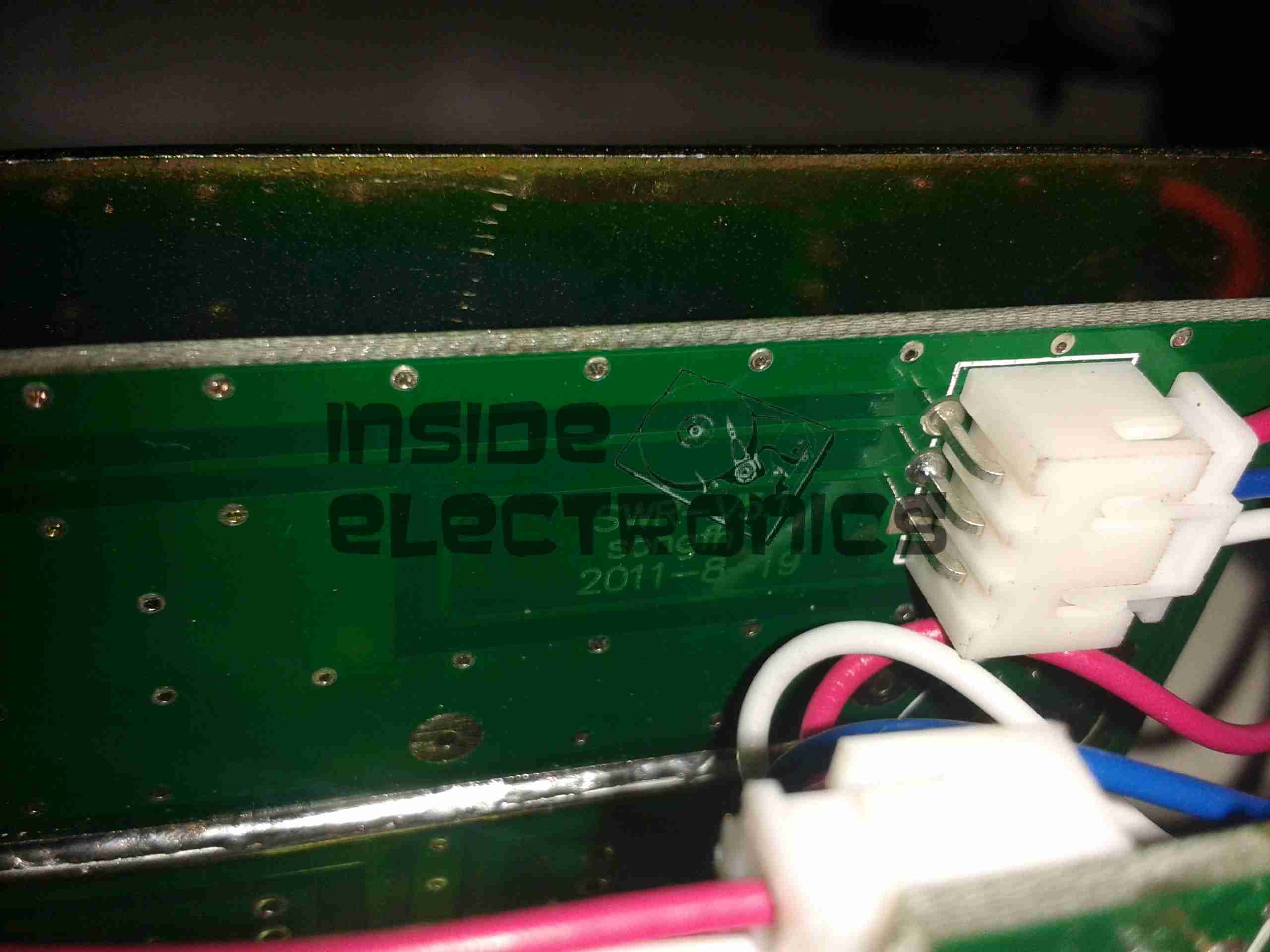
PCB Marking
The PCB is dated 19-8-2011, so it’s a fairly old design.
Adjustments
Here is visible the back of the user calibration adjuster, with the factory calibration trimmer.
Meter Movement
Back of the meter movement. This is a standard moving coil type. Nothing special.
This meter will soon be modified to accept connection of an external Arduino-based SWR & power meter, which I can calibrate individually for each band.
Stay tuned for that upcoming project.
After watching a video over at Scullcom Hobby Electronics on YouTube, I figured I’d build one of these precision references to calibrate my multimeters.
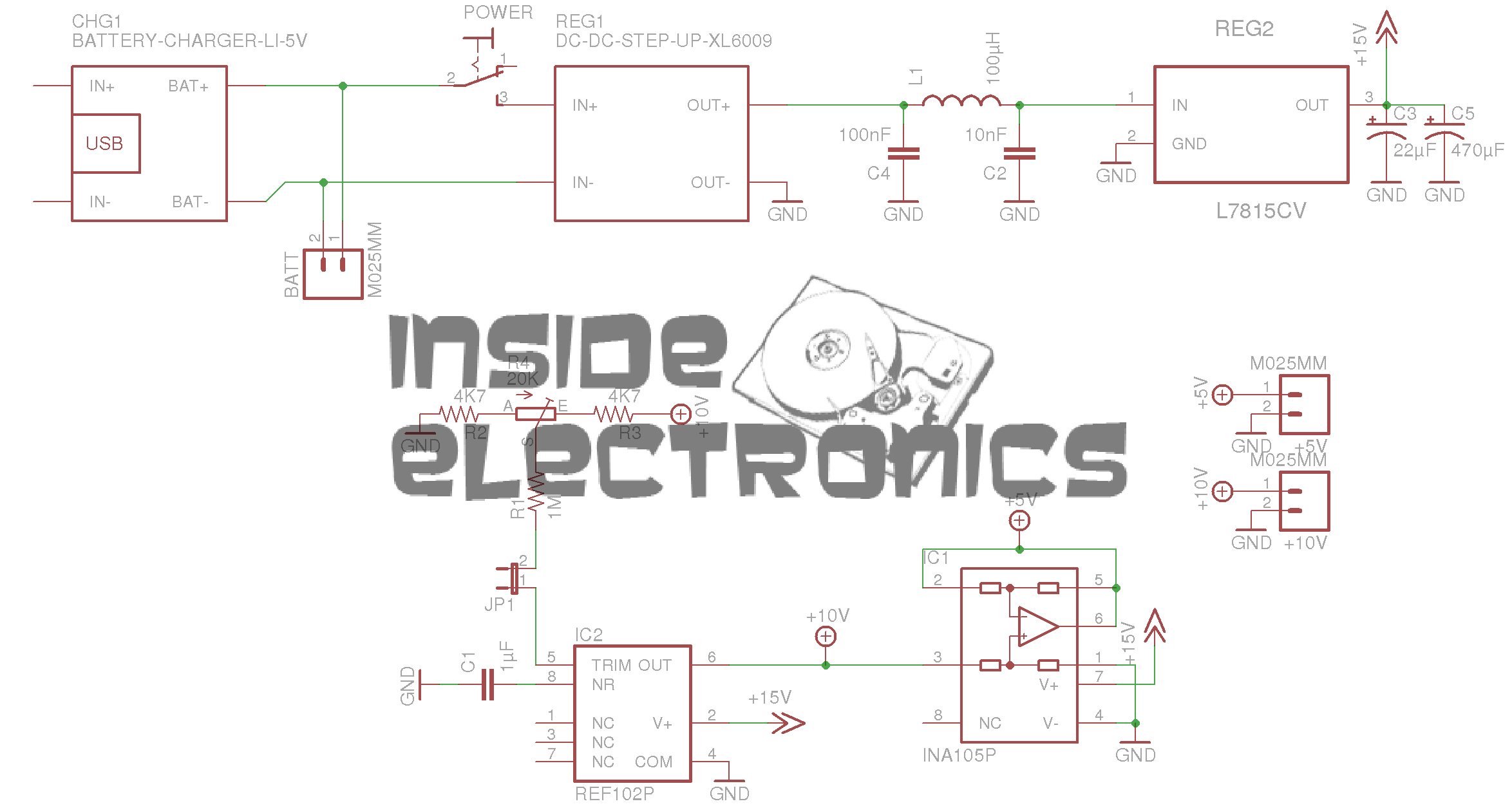
It’s based around a REF102P 10v precision reference & an INA105P precision unity gain differential amplifier.
For full information, check out the video, I won’t go into the details here, just my particular circuit & PCB layout.
In the video, Veroboard is used. I’m not too fond of the stuff personally. I find it far too easy to make mistakes & it never quite looks good enough. To this end I have spun a board in Eagle, as usual.
Precision Ref SCH – Click to Embiggen
Here’s the schematic layout, the same as is in the video.
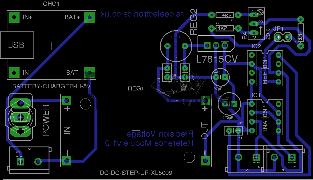
Precision Ref BRD
As usual, the Eagle CAD layout files can be found at the bottom of the post.
And the associated PCB layout. I have added the option to be able to tweak the output, to get a more accurate calibration, which can be added by connecting JP1 on the PCB.
As in the original build, this unit uses pre-built DC-DC converter & Li-Ion charger modules. A handy Eagle library can be found online for these parts.
I have however left off the battery monitor section of the circuit, since I plan to use a protected lithium cell for power. This also allowed me to keep the board size down, & use a single sided layout.
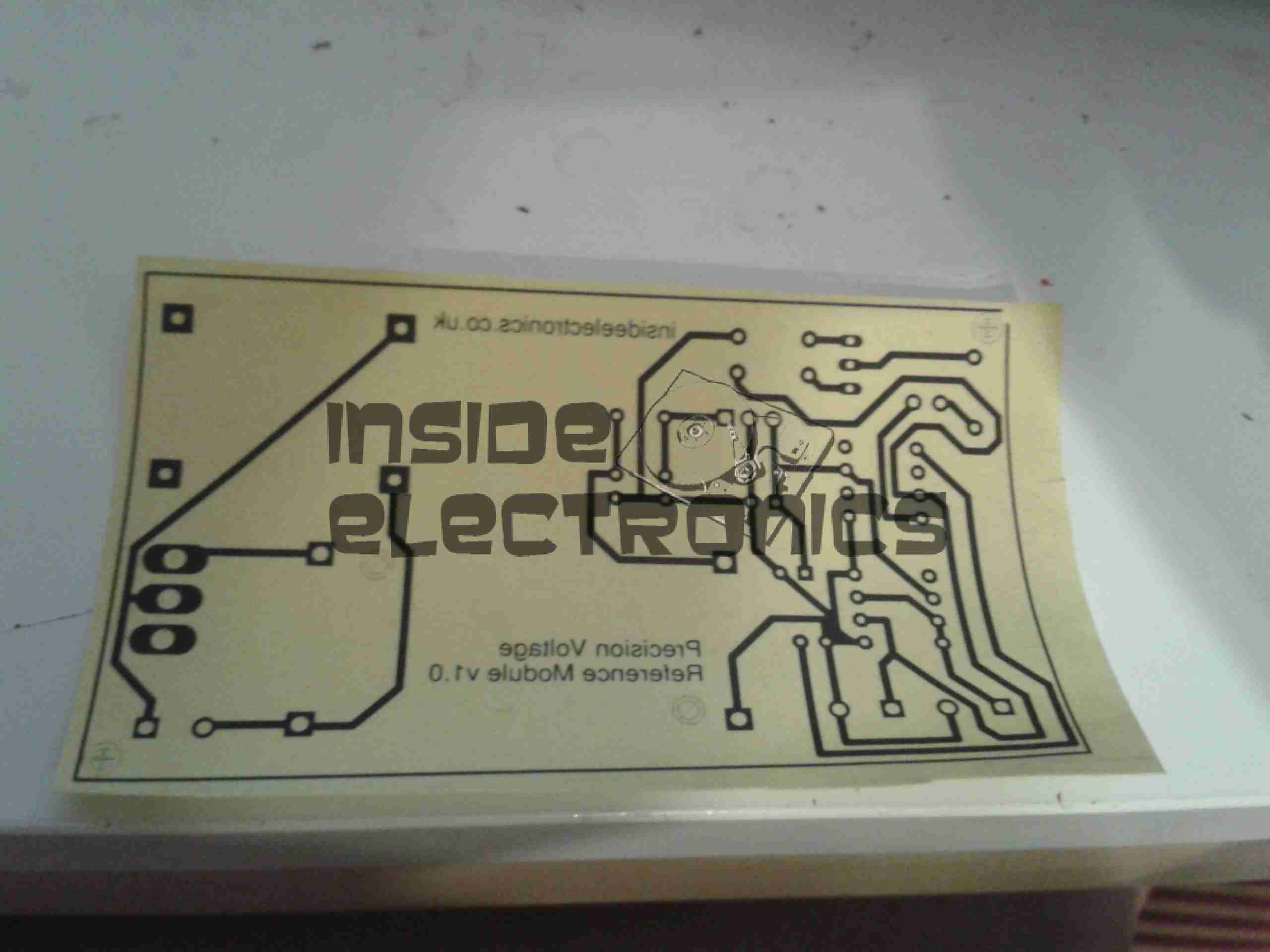
Toner Transfer Paper
Here’s the track layout ready to iron onto the copper clad board. I use the popular toner transfer system with special paper from eBay, this stuff has a coating that allows the toner to easily be transferred to the PCB without having to mess about with soaking in water & scraping paper off.
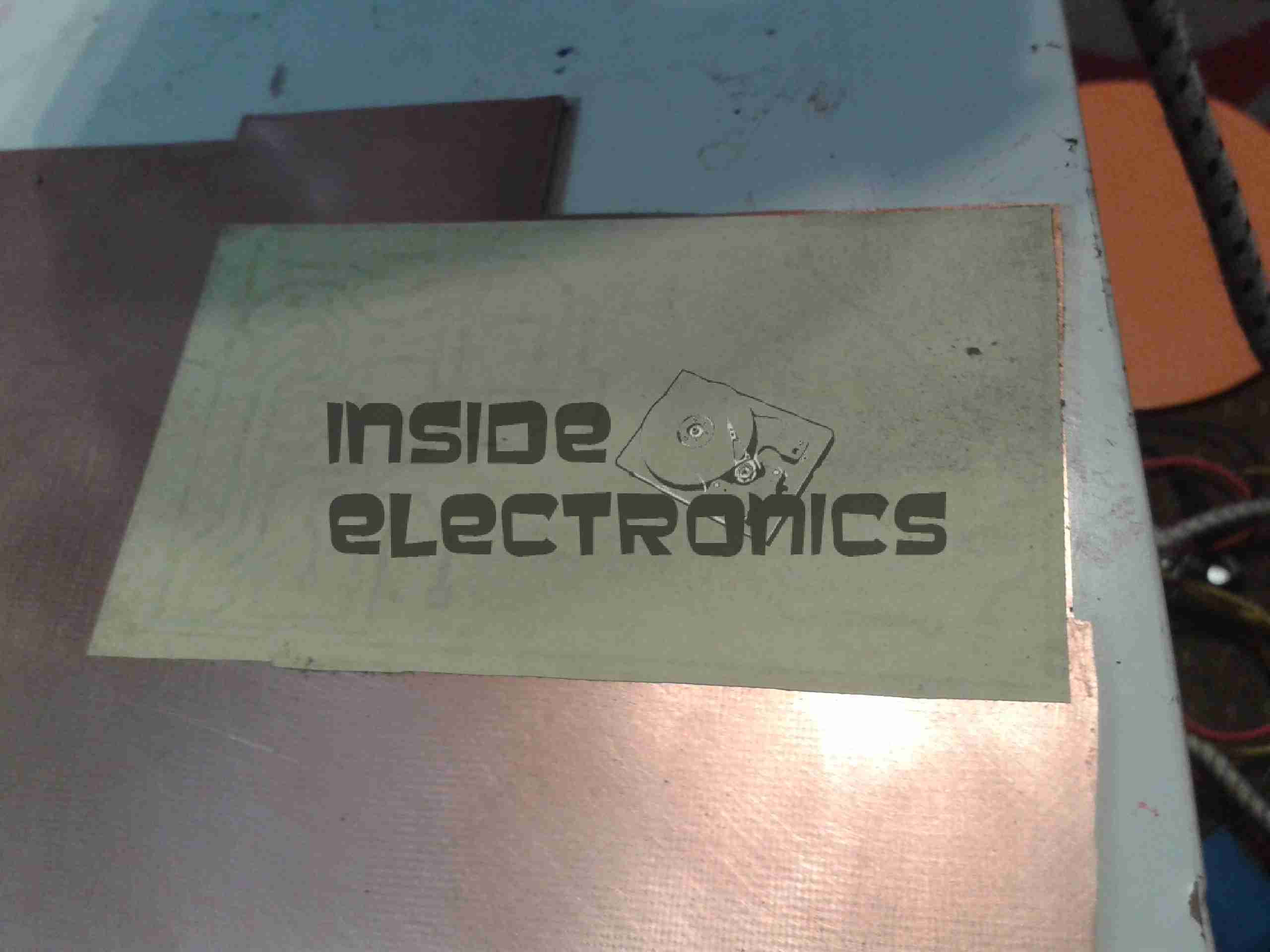
Ironed On
Here’s the paper having just been ironed onto the copper. After waiting for the board to cool off the paper is peeled off, leaving just the toner on the PCB.
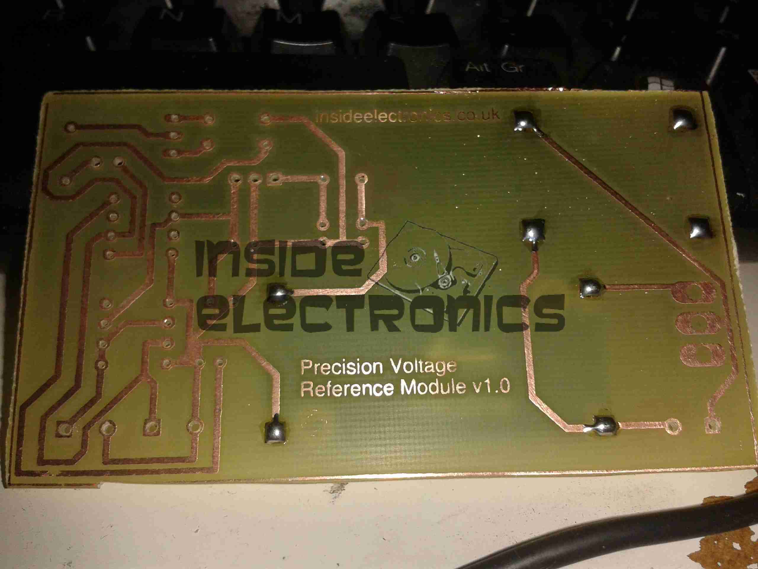
Etched PCB
PCB just out of the etch tank, drilled & with the solder pins for the modules installed. Only one issue with the transfer, in the bottom left corner of the board is visible, a very small section of copper was over etched.
This is easily fixed with a small piece of wire.
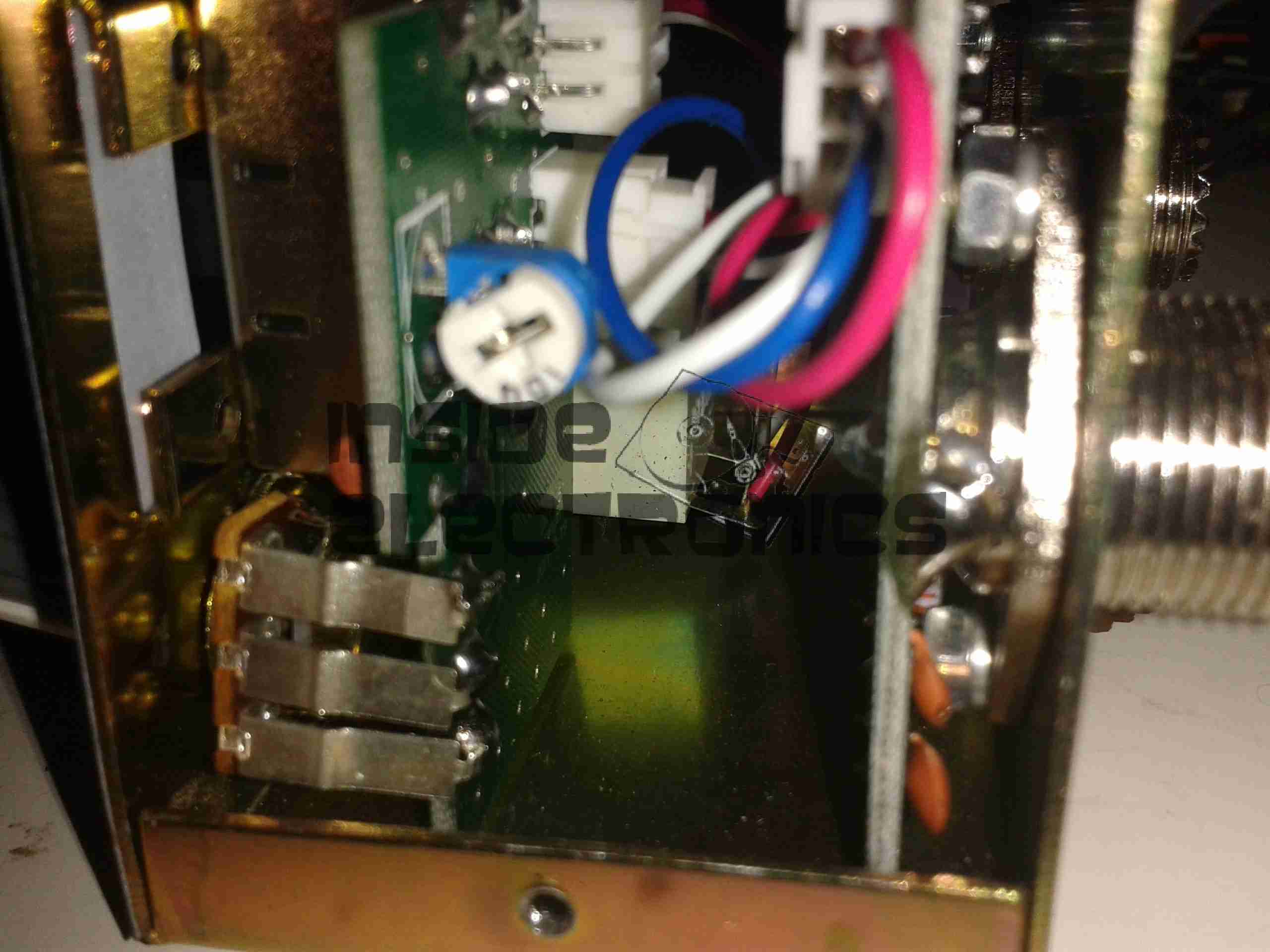
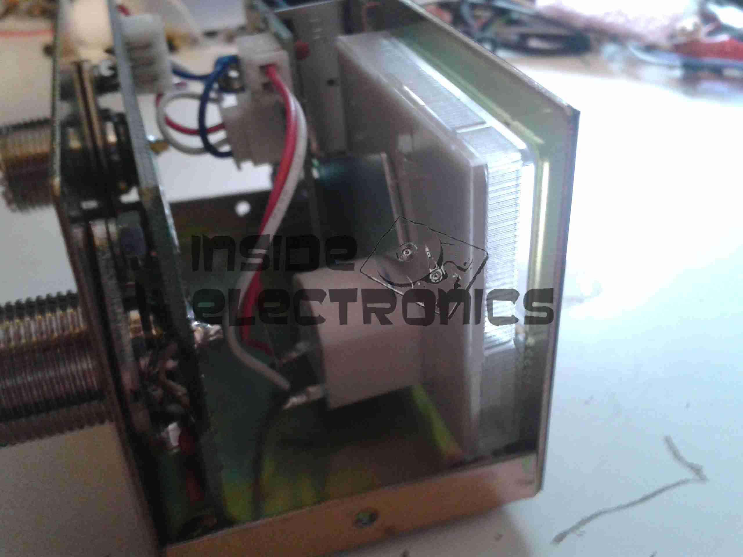
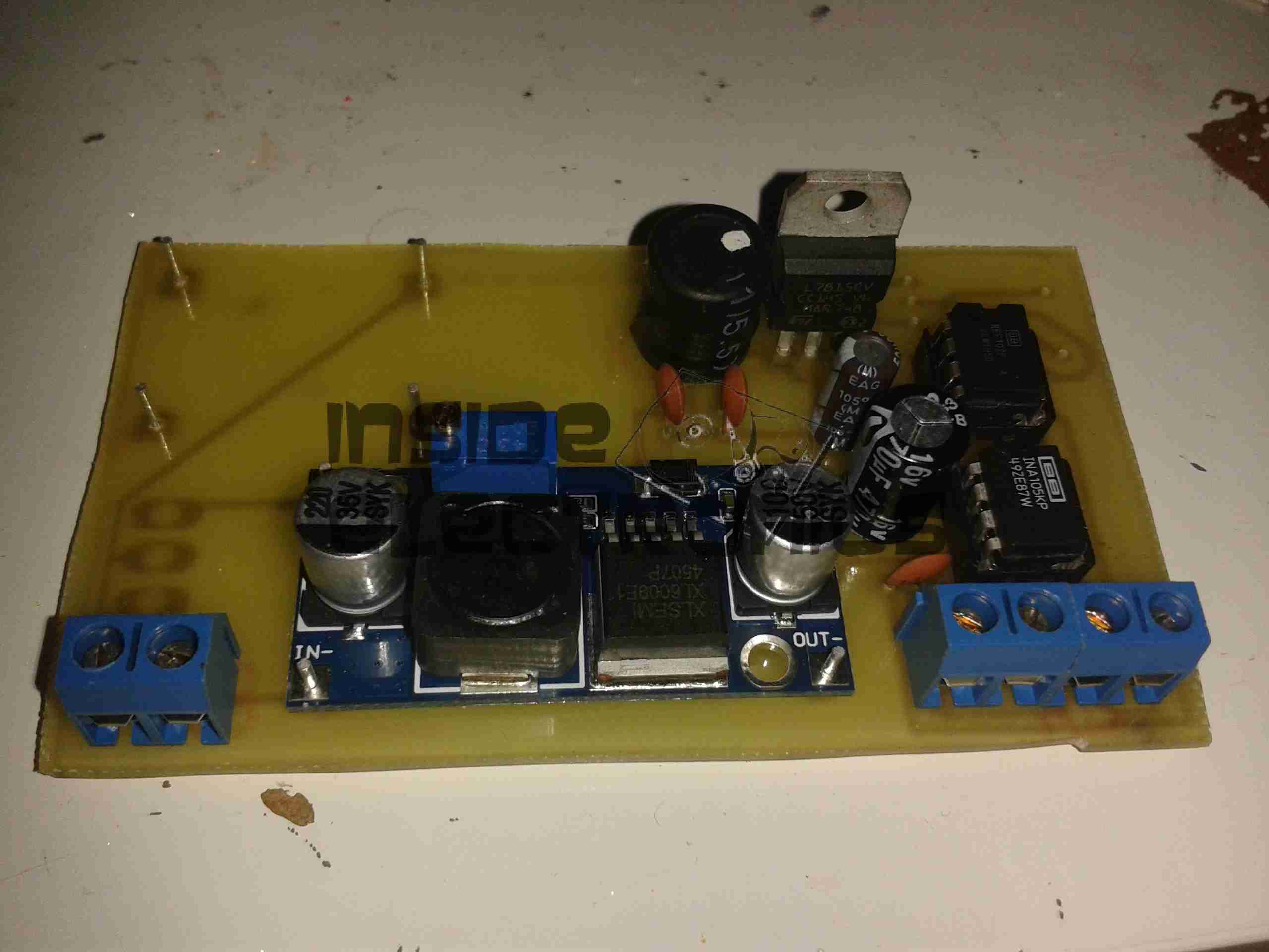
Components Populated
Main components populated. The DC-DC converter is set at 24v output, which the linear regulator then drops down to the +15v rail for the reference IC. The linear section of the regulator, along with the LC filter on the output of the switching regulator produce a low-ripple supply.
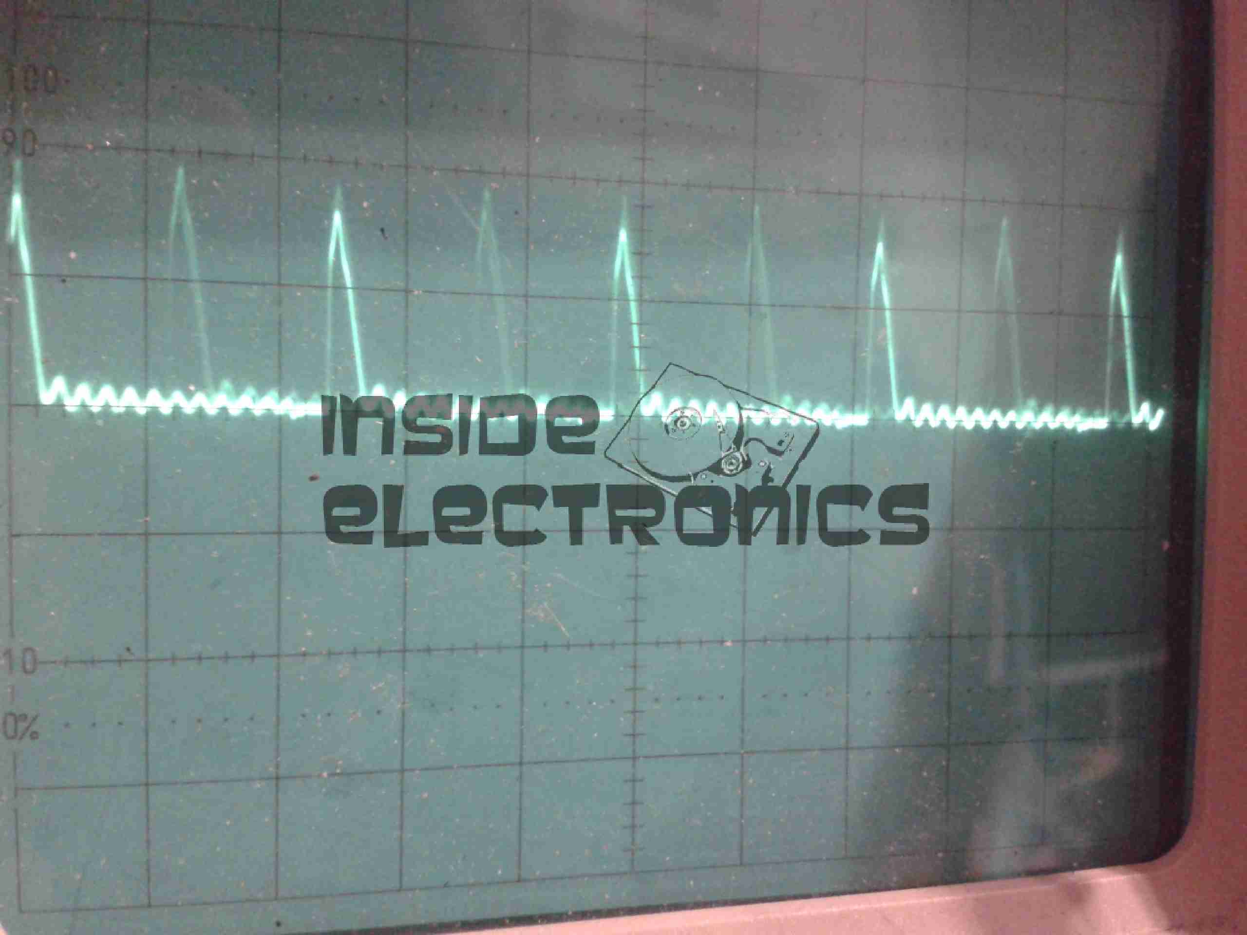
SMPS Ripple
Here’s the scope reading the AC ripple on the output of the DC-DC converter. Scale is 100mV/Div. Roughly 150mV of ripple is riding on top of the DC rail.
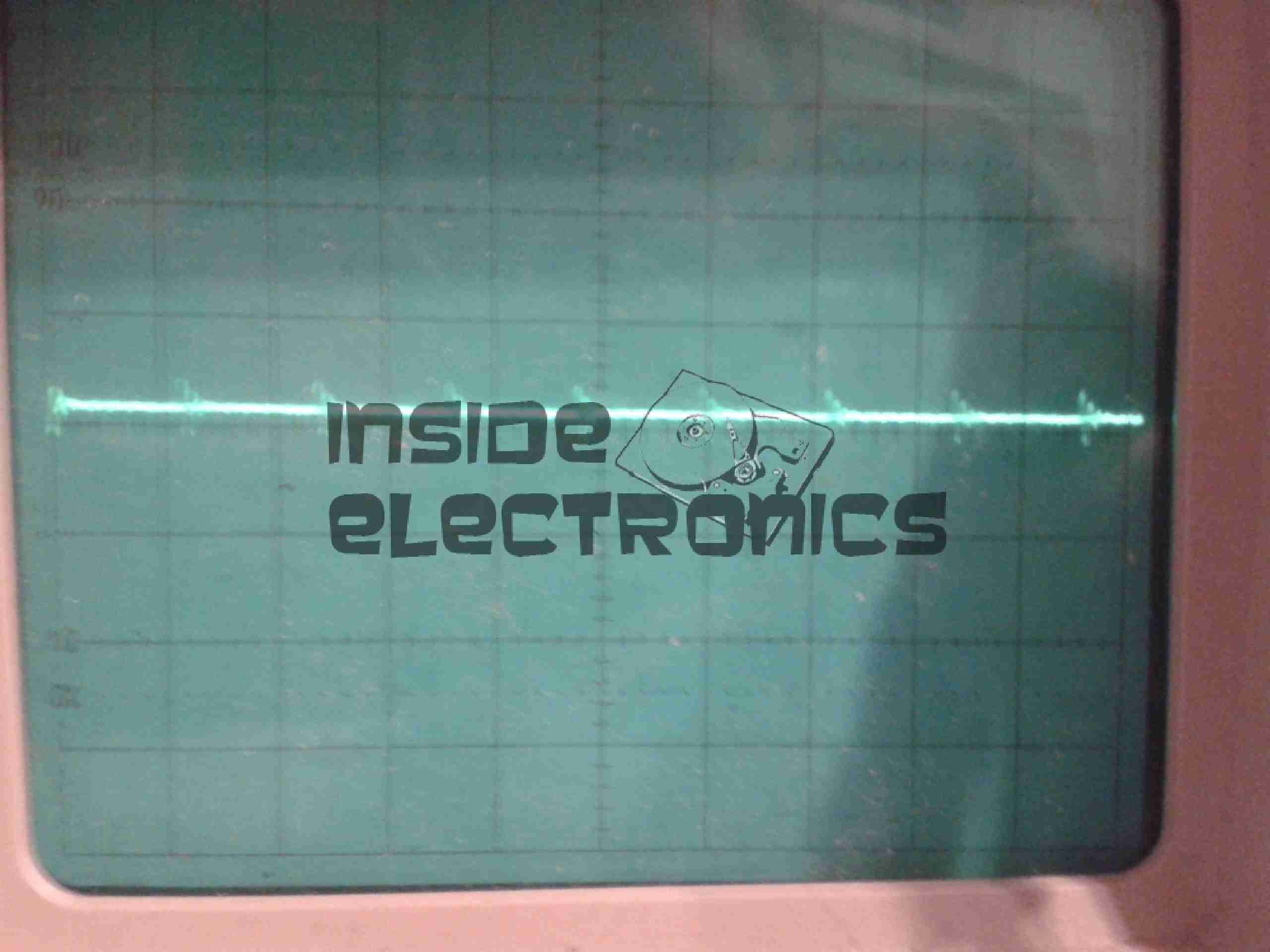
Linear PSU Ripple
And here’s the output from the linear regulator, scale of 50mV/Div. Ripple has been reduced to ~15mV for the reference IC.
In total the circuit as built has a power consumption of ~0.5W, most of which is being dissipated as heat in the linear part of the PSU.
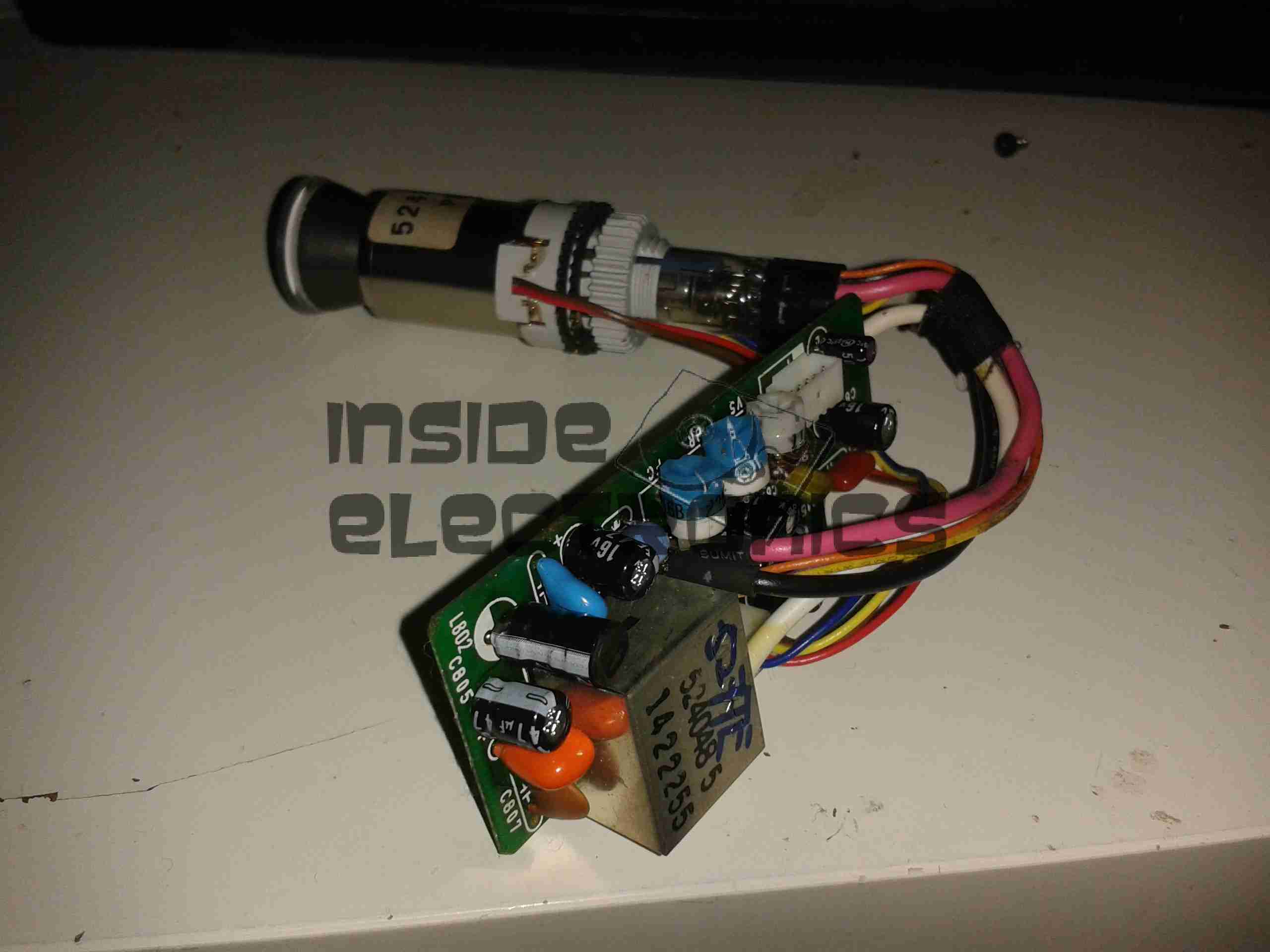
Here’s another viewfinder CRT, removed from a 1980’s vintage VHS camera I managed to get cheap from eBay.
This unit is very similar to the last one I posted about, although there are a few small differences in the control circuitry.
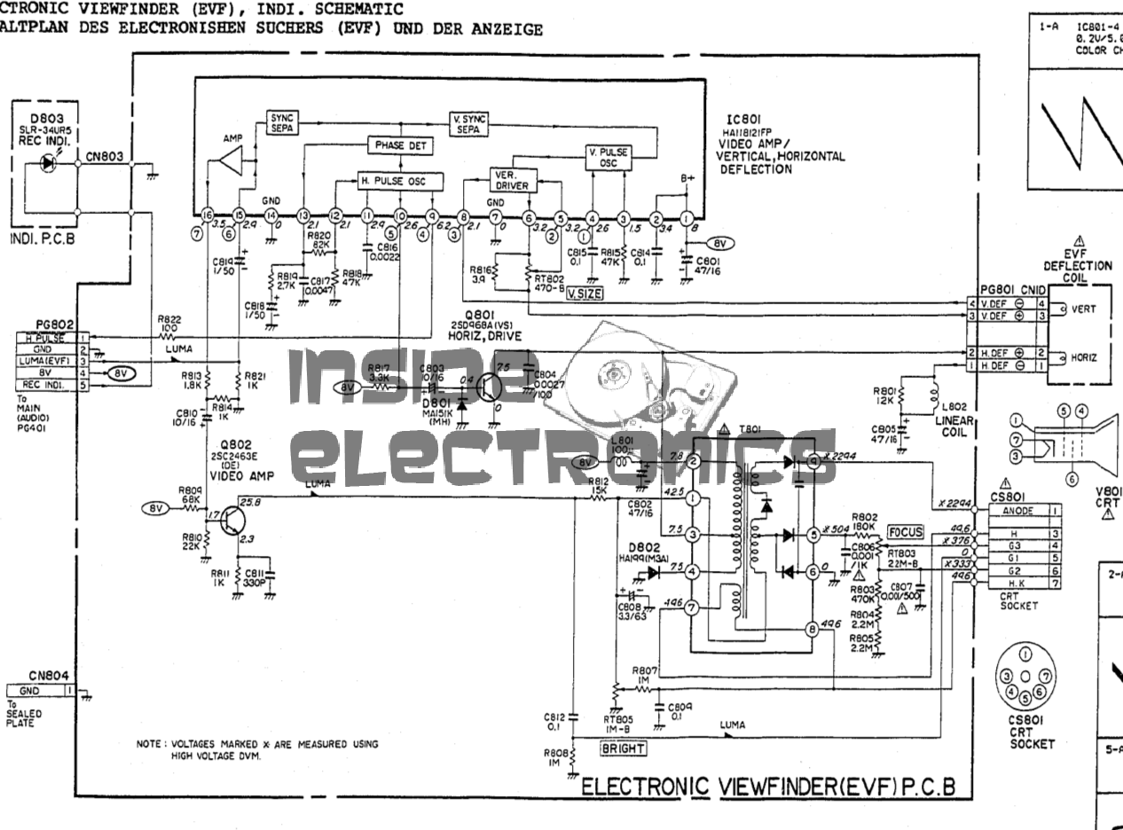
Viewfinder Schematic – Click to Embiggen
Here’s the schematic, showing all the functional blocks of the viewfinder circuitry. An integrated viewfinder IC is used, which generates all the required scan waveforms for the CRT.
On the left is the input connector, with the power & video signals. Only pins 2 (GND), 3 (Composite video), & 4 (+8v) are needed here. Pin 1 outputs a horizontal sync signal for use elsewhere in the camera, while pin 5 fed the recording indicator LED.
To make connection easier, I have rearranged the wires in the input connector to a more understandable colour scheme:
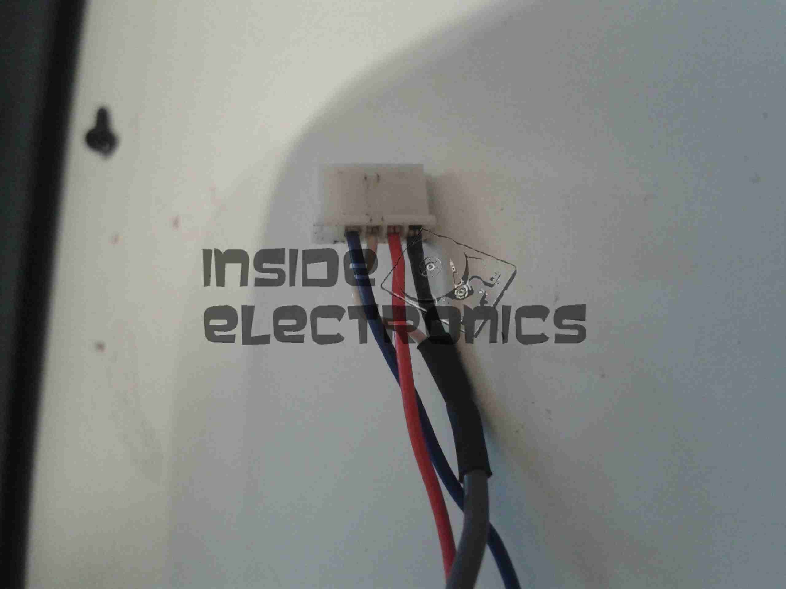
Input Connector
Red & Blue for power input, & a coax for the video. For the video GND connection, I have repurposed the Rec. LED input pin, putting a shorting link across where the LED would go to create a link to signal ground. Keeping this separate from the power GND connection reduces noise on the CRT.
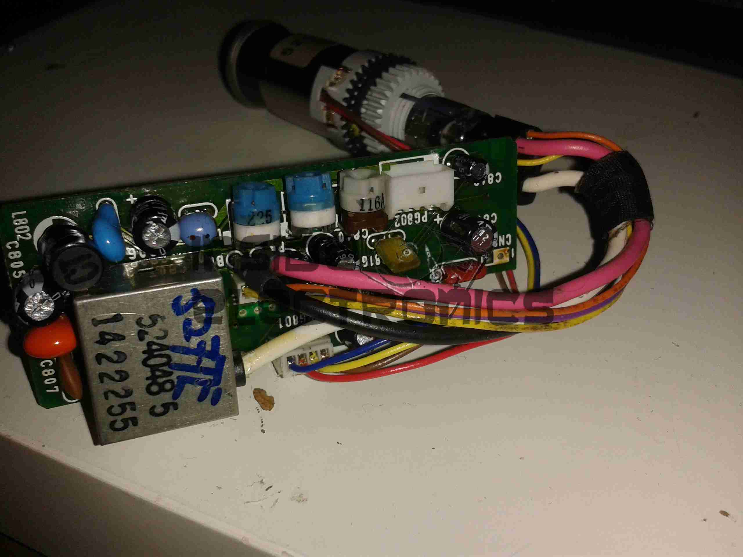
Viewfinder CRT Assembly
Here’s the complete assembly liberated from it’s plastic enclosure.
PCB Closeup
Closeup of the control PCB. The 3 potentiometers control the CRT brightness, focus & vertical size.
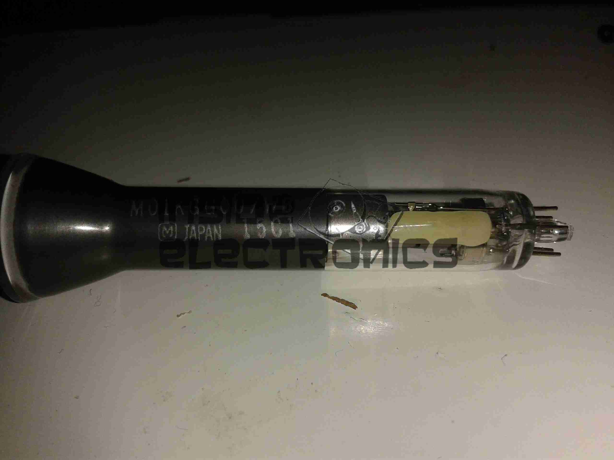
M01KGG007WB CRT
The tiny CRT. Only ~60mm in length, with an 18mm screen size. This tube runs on +2294v final anode voltage. Much higher than I expected.
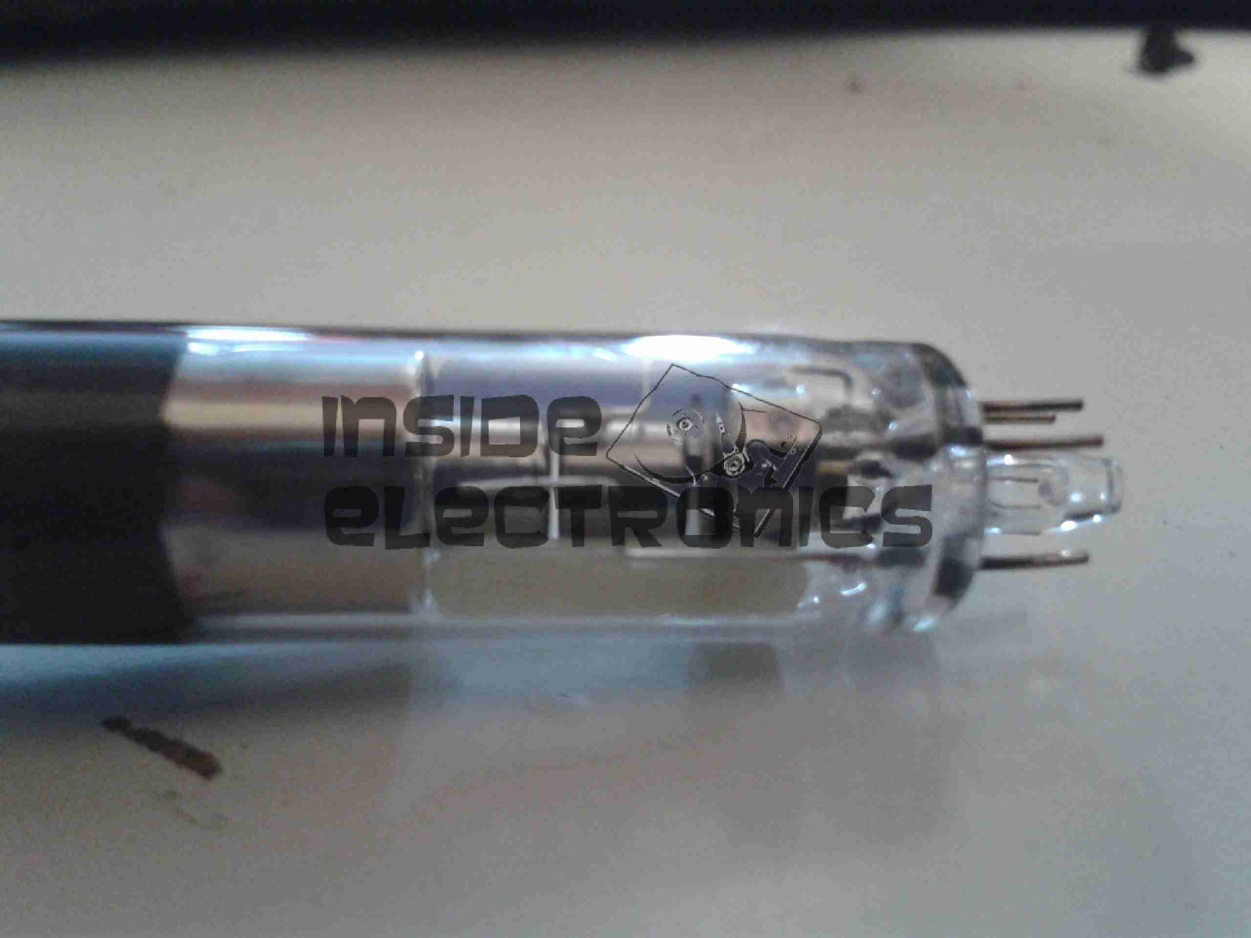
Electron Gun Closeup
The electron gun assembly, with the cathode, focus & final anode cups.
Phosphor Screen
This screen is just a little bigger than a UK 5p piece! A marvel of precision engineering.
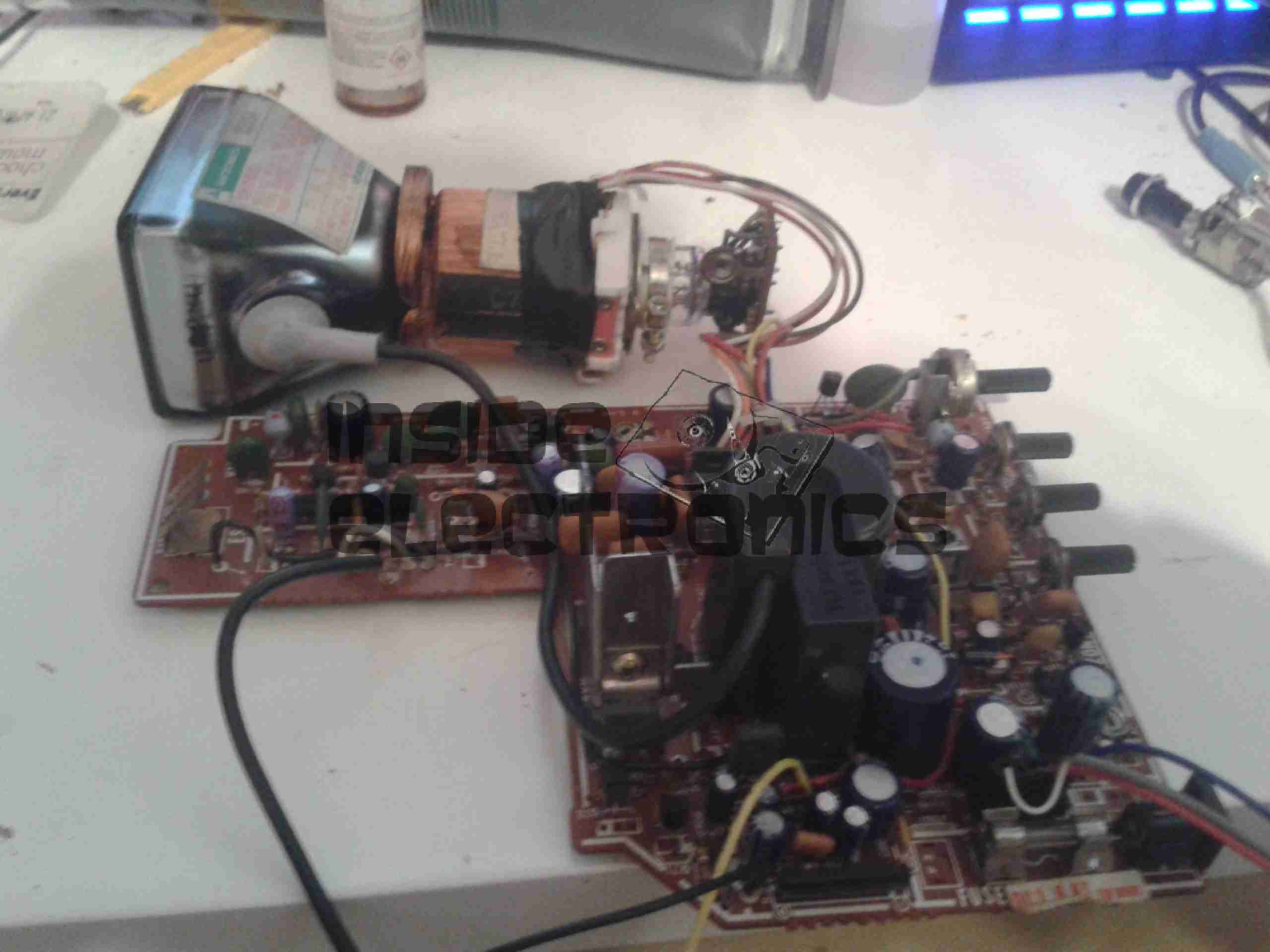
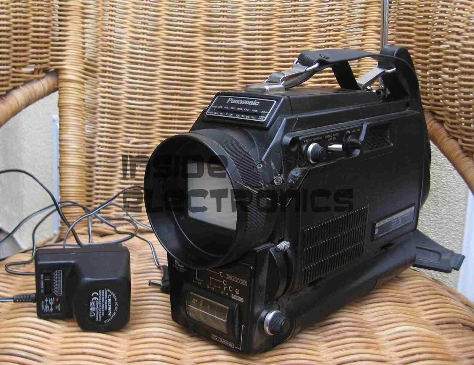
I recently managed to score a 3″ B&W portable TV on eBay, a Panasonic TR-3000G. As these old units are now useless, thanks to the switch off of analogue TV signalling, I figured I could find a composite signal internally & drive the CRT with an external source.
Panasonic TR-3000G
Here’s the TV in it’s native state. Running from 9v DC, or 6 D size cells. I’m guessing from somewhere around the 1970’s. Here is the CRT & associated drive circuitry, removed from the casing:
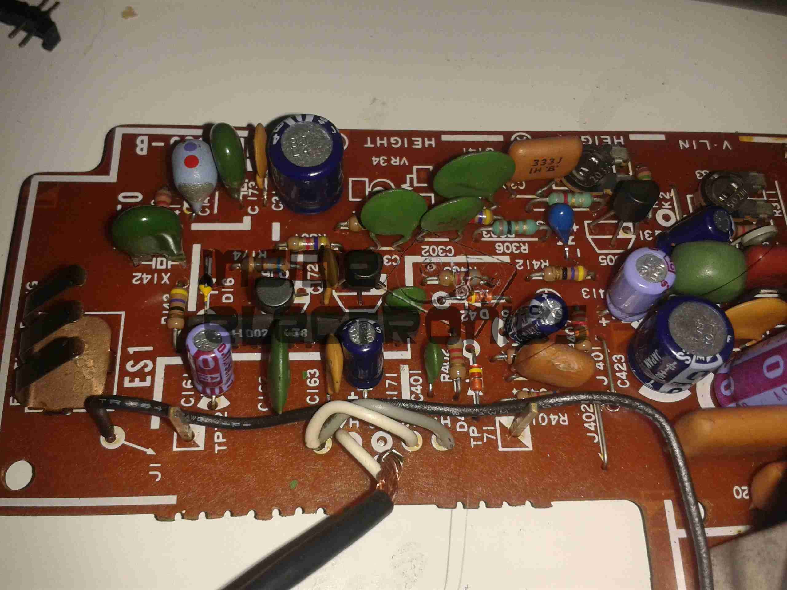
CRT Module
After dissecting the loom wiring between the CRT board & the RF/tuner board, I figured out I had to short out Pins 1,2 & 5 on the H header to get the CRT to operate straight from the power switch. This board also generates the required voltages & signals to drive the RF tuner section. I have removed the loom from this, as the PCB operates fine without. It doesn’t seem to be fussy about power input either: it’s specified at 9v, but seems to operate fine between 7.5v & 14.5v DC without issue.
Video Connections
Tracing the wiring from the tuner PCB revealed a length of coax snaking off to the section marked Video/Sync. I successfully found the composite input!
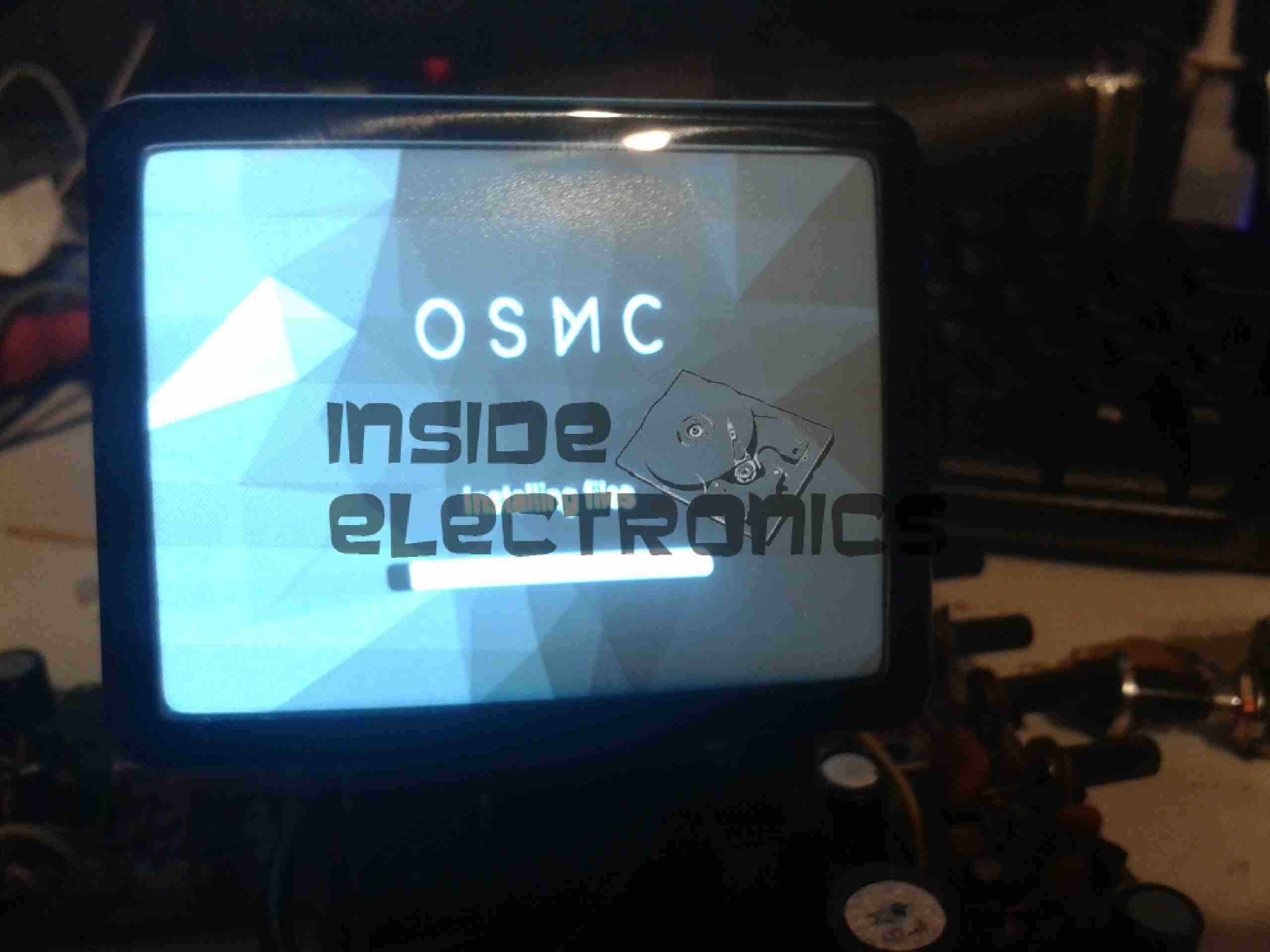
Running OSMC
A quick bit of wiring to a Raspberry Pi, & we have stable video! For such an old unit, the picture quality is brilliant, very sharp focus.
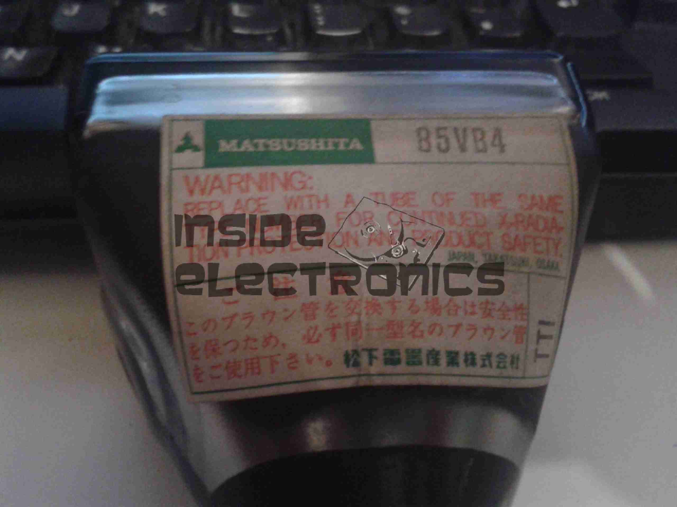
Matsushita 85VB4 CRT
Closeup of the CRT itself. I haven’t been able to find much data on this unit, but I’m guessing it’s similar to many commercial viewfinder CRTs.
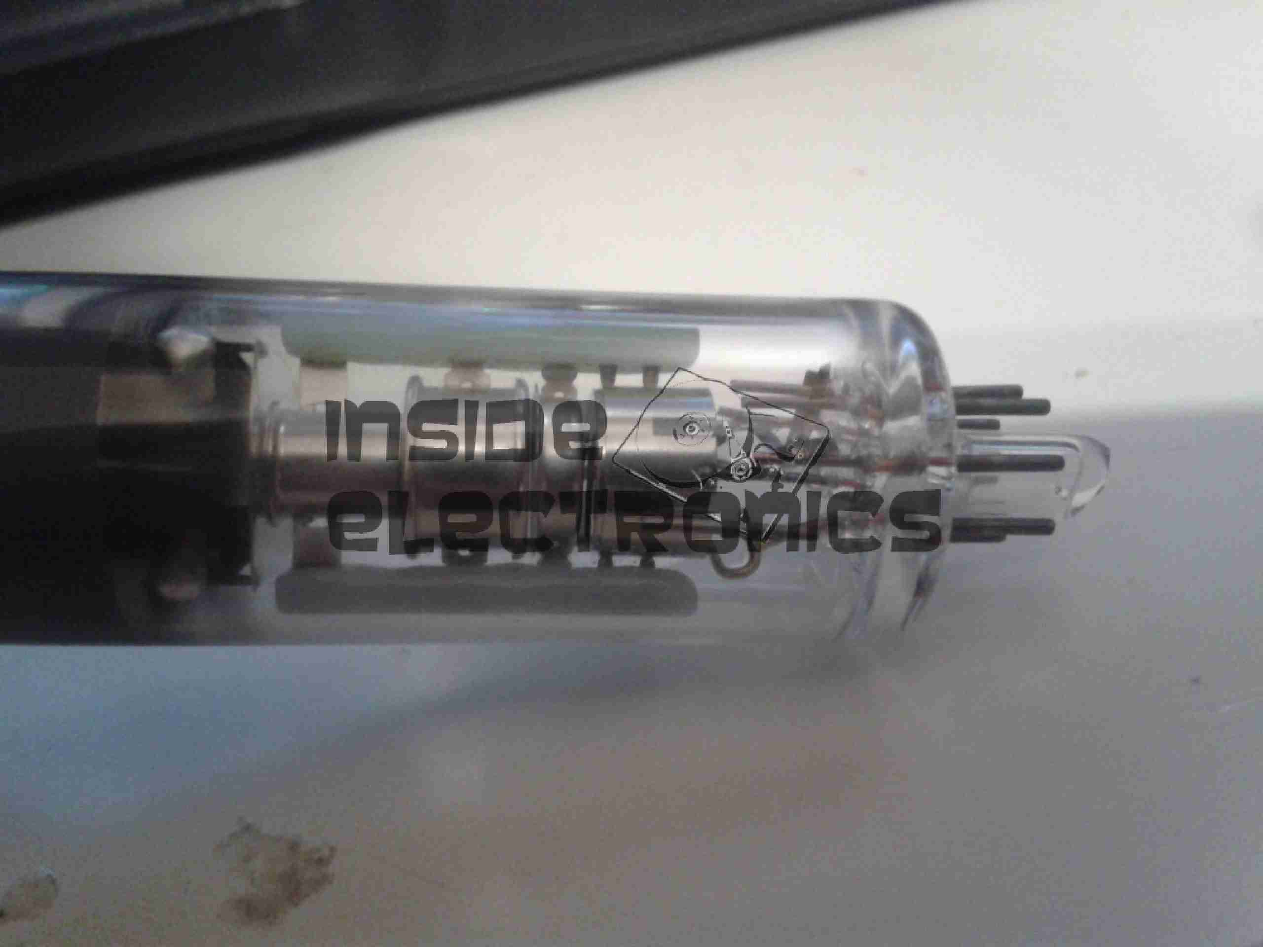
Electron Gun Closeup
Amazingly, there isn’t a single IC in the video circuitry, it’s all discrete components. This probably accounts for the large overall size of the control PCB. Viewfinder CRTs from a few years later on are usually driven with a single IC & a few passives that provide all the same functions.
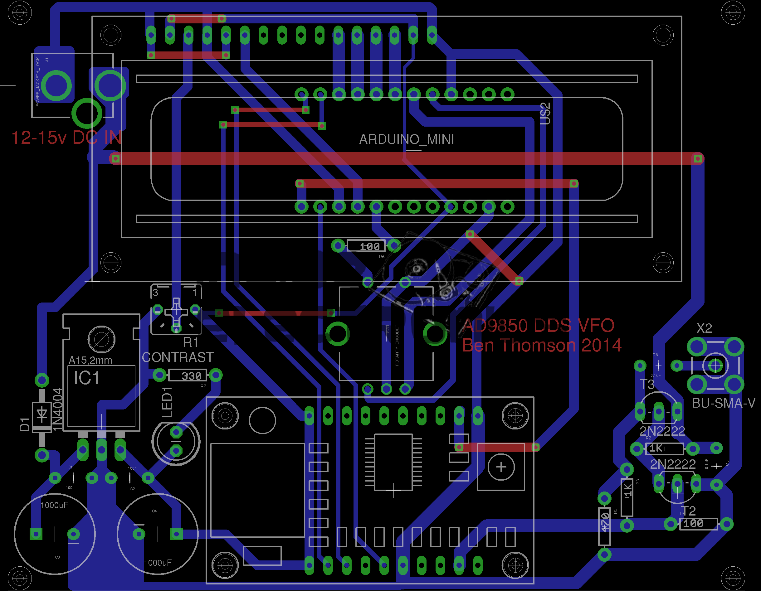
I recently came across a design for an Arduino controlled AD9850 DDS module, created by AD7C, so I figured I would release my Eagle CAD design for the PCB here.
It is a mainly single-sided layout, only a few links on the top side are needed so this is easy to etch with the toner transfer method.
My version uses an Arduino Pro Mini, as the modular format is much easier to work with than a bare ATMega 328.
RF output is via a SMA connector & has a built in amplifier to compensate for the low level generated by the DDS Module.
DDS VFO
Version 2 Update: Added reverse polarity protection, added power indicator LED, beefed up tracks around the DC Jack.
[download id=”5571″]
Tip Jar
If you’ve found my content useful, please consider leaving a donation by clicking the Tip Jar below!
All collected funds go towards new content & the costs of keeping the server online.