Since I fitted my scope with a SMPS based 12v input supply, there has been a noise problem on very low volts/div settings, this noise isn’t present on the mains supply, so I can only think it’s coming from the switching frequencies of the various DC-DC modules I’ve used.
Scope Ripple
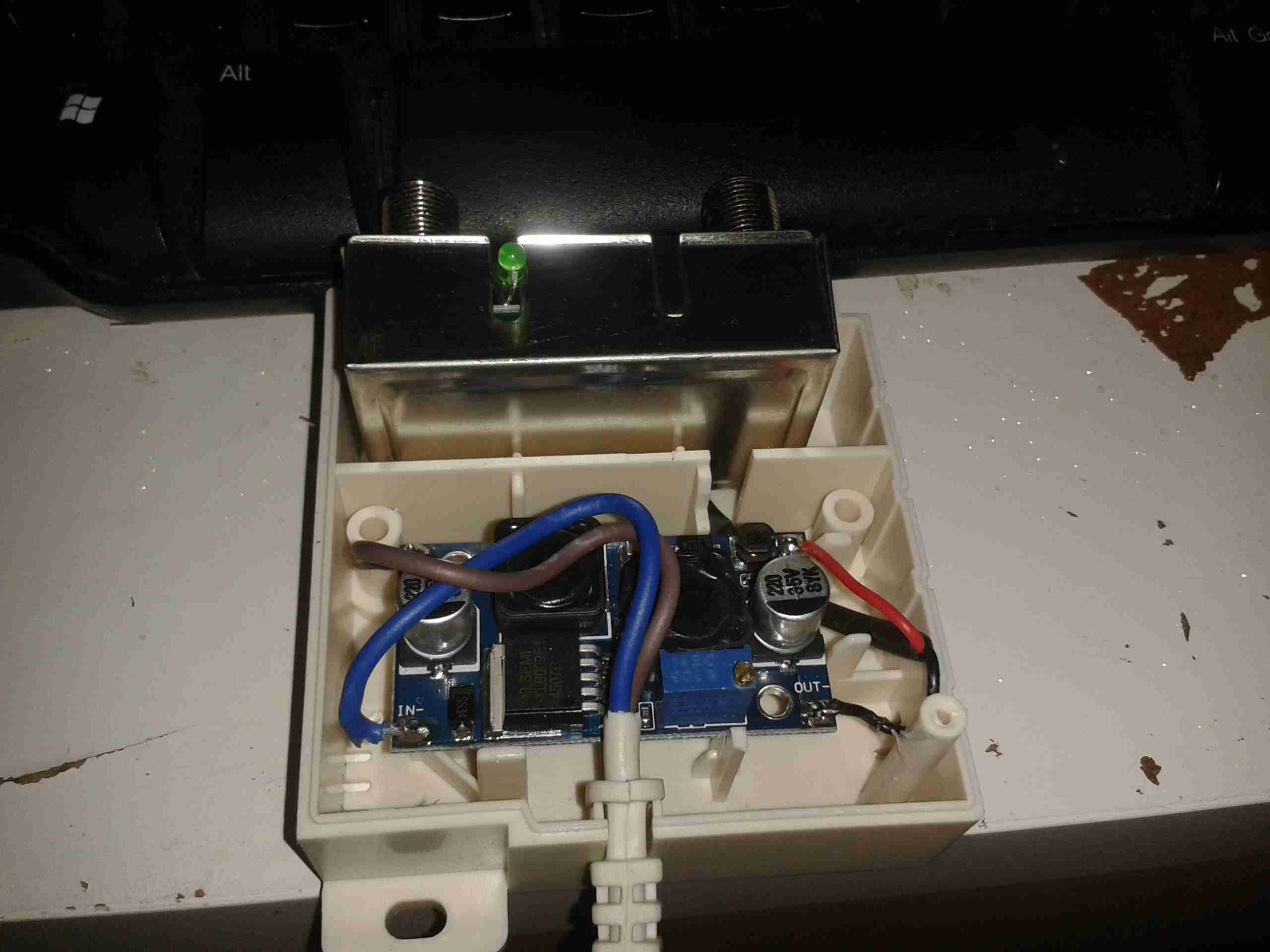
Because of this I’ve designed a linear post-regulation stage for the supply, to remove the RFI from the DC rails.
This board takes the outputs from the DC-DC converters, removes all the noise & outputs clean DC onto the mainboard of the scope.
As the scope internally uses regulation to get the voltages lower, I’ve found that I don’t have to match the outputs of the mains supply exactly, for the +/-17.5v rails, 12v is perfectly fine instead.
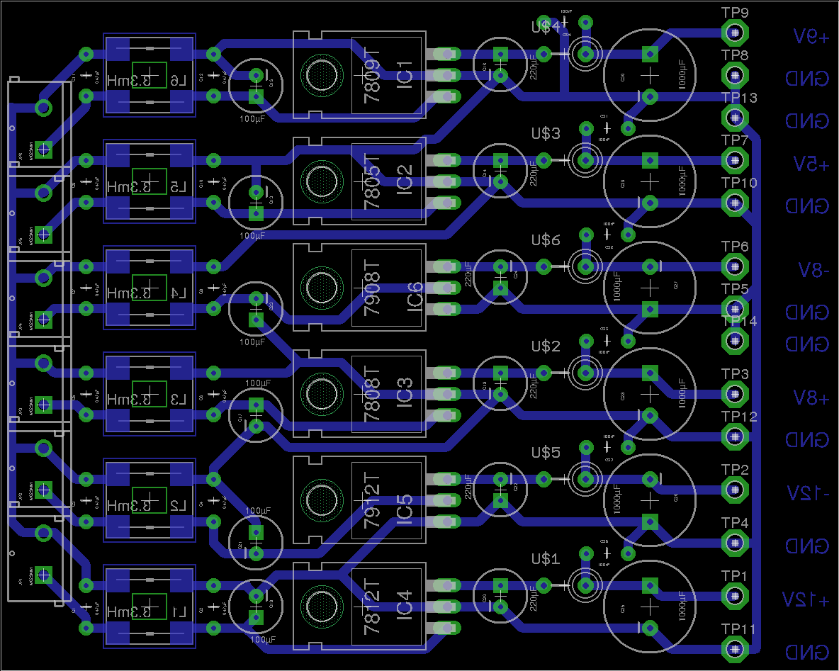
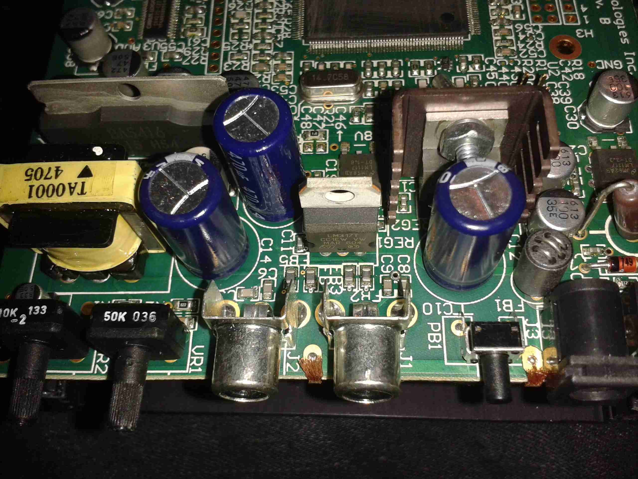
Scope Linear PSU
Here’s the PCB layout, with the 6 common mode filters on the input (left), linear regulator ICs in the centre & the output filters on the right.
Scope Linear PSU
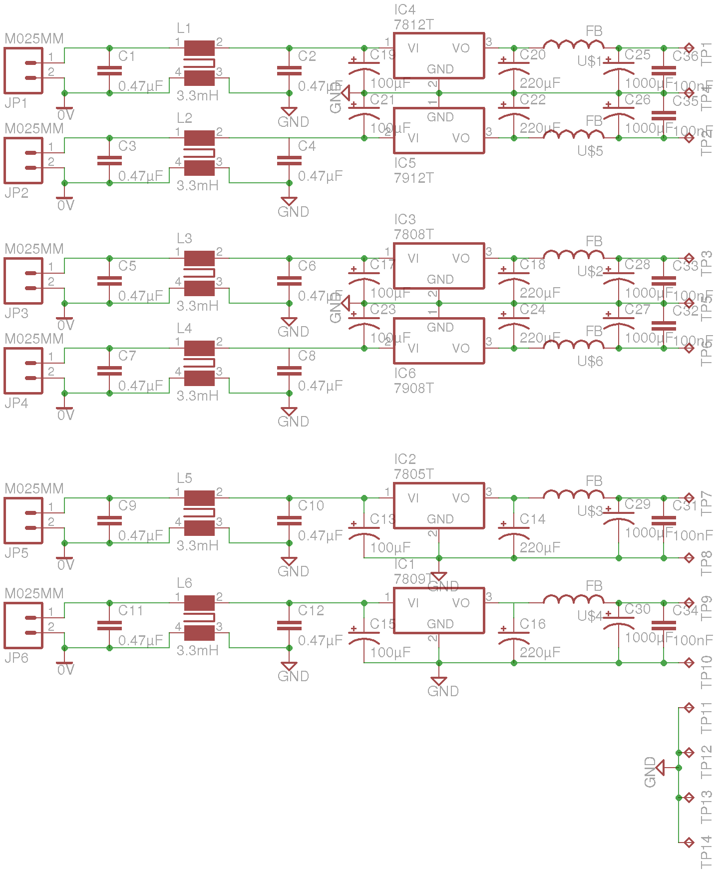
Here’s the schematic layout, as usual the Eagle Project files are in the link below, I’ll update when I have built the board & tested!
This is basically an industrial, rugged MP3 player, in an extruded aluminium case.
They are used in commercial settings for generating telephone hold music or continual playback of background music in shops.
USB1100
It’s quite a compact unit, in a nice aluminium case, designed for mounting into a comms setup. This unit will play any MP3 file, up to a maximum size of 11MB.
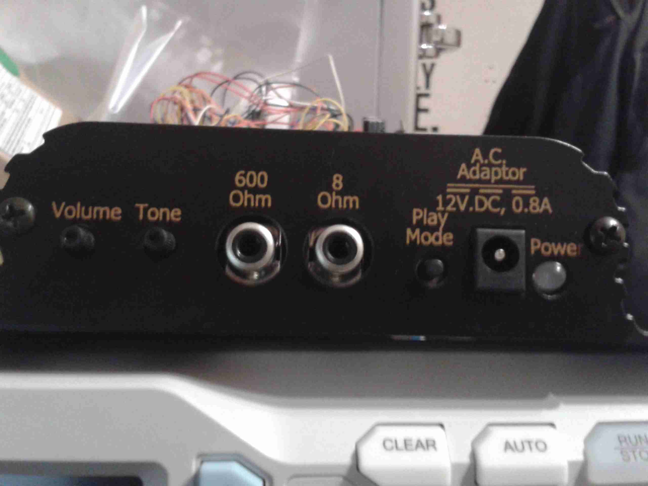
Connections
Here’s the user connections on the end of the unit. The device takes a standard 12v DC input, and has a single button for setup, user feedback is given through the multi-colour LED next to the power jack.
Both 8Ω & 600Ω audio outputs are provided for maximum compatibility. Volume & tone controls are also here.
On the other end of the unit is a single USB port for loading the audio files from a USB drive, and a reset button.
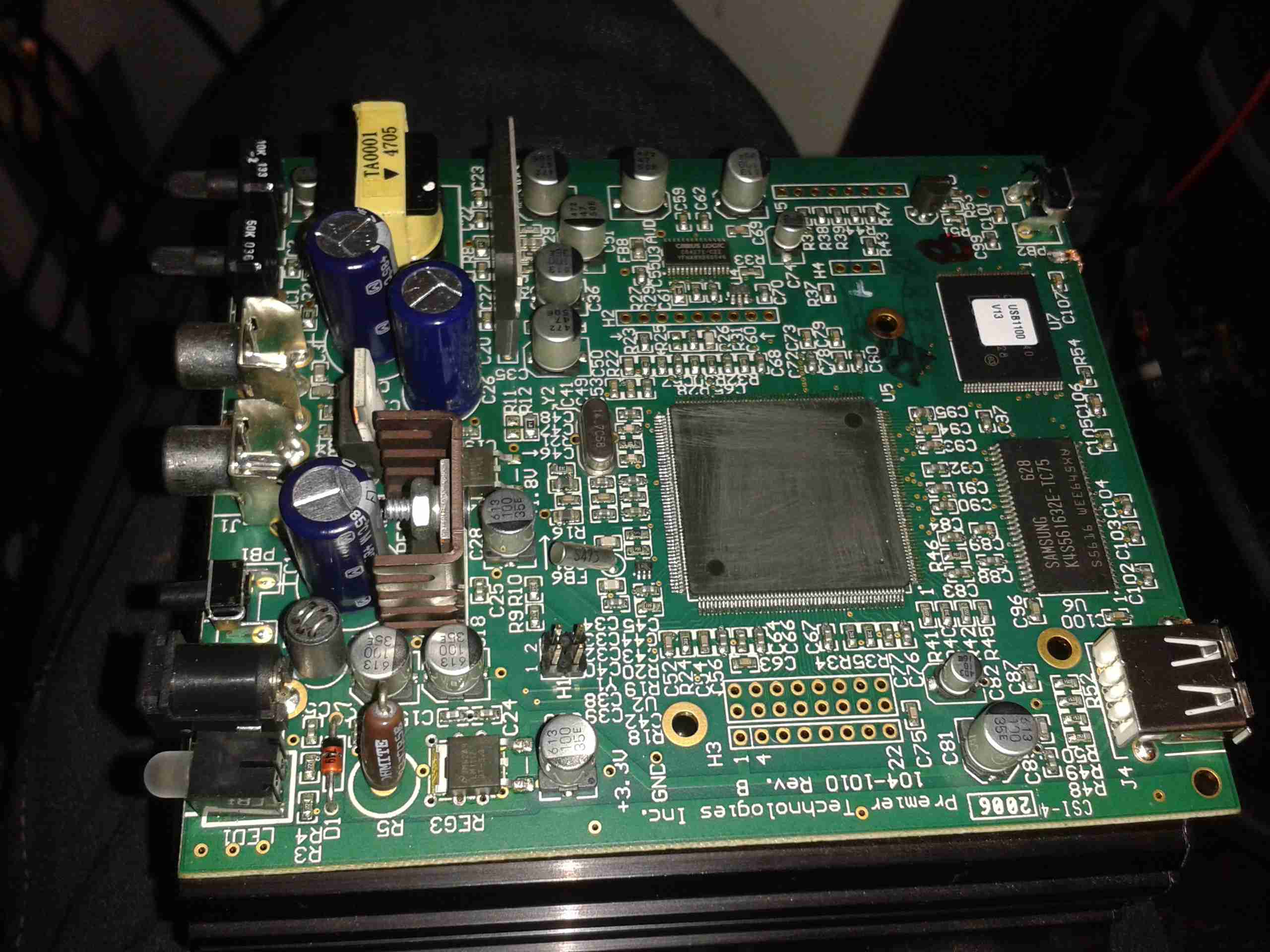
Main PCB
Here’s the single PCB removed from the casing. Unfortunately the main CPU has had it’s part number sanded off, and I can’t be bothered to try & find out what kind of processor it is at this point. To the right of the CPU are some flash ROM & SDRAM, along with the single USB port at bottom right.
The left side of the board is dedicated to audio output & voltage regulation, there are a fair few linear regulators in this unit.
Audio End
Here’s the audio output side of the board, the transformer on the left is to provide the 600Ω output, the audio amplifier IC (BA5416) is just behind it. To the right are some of the main voltage regulators, a 5v one on the heatsink & a LM317.
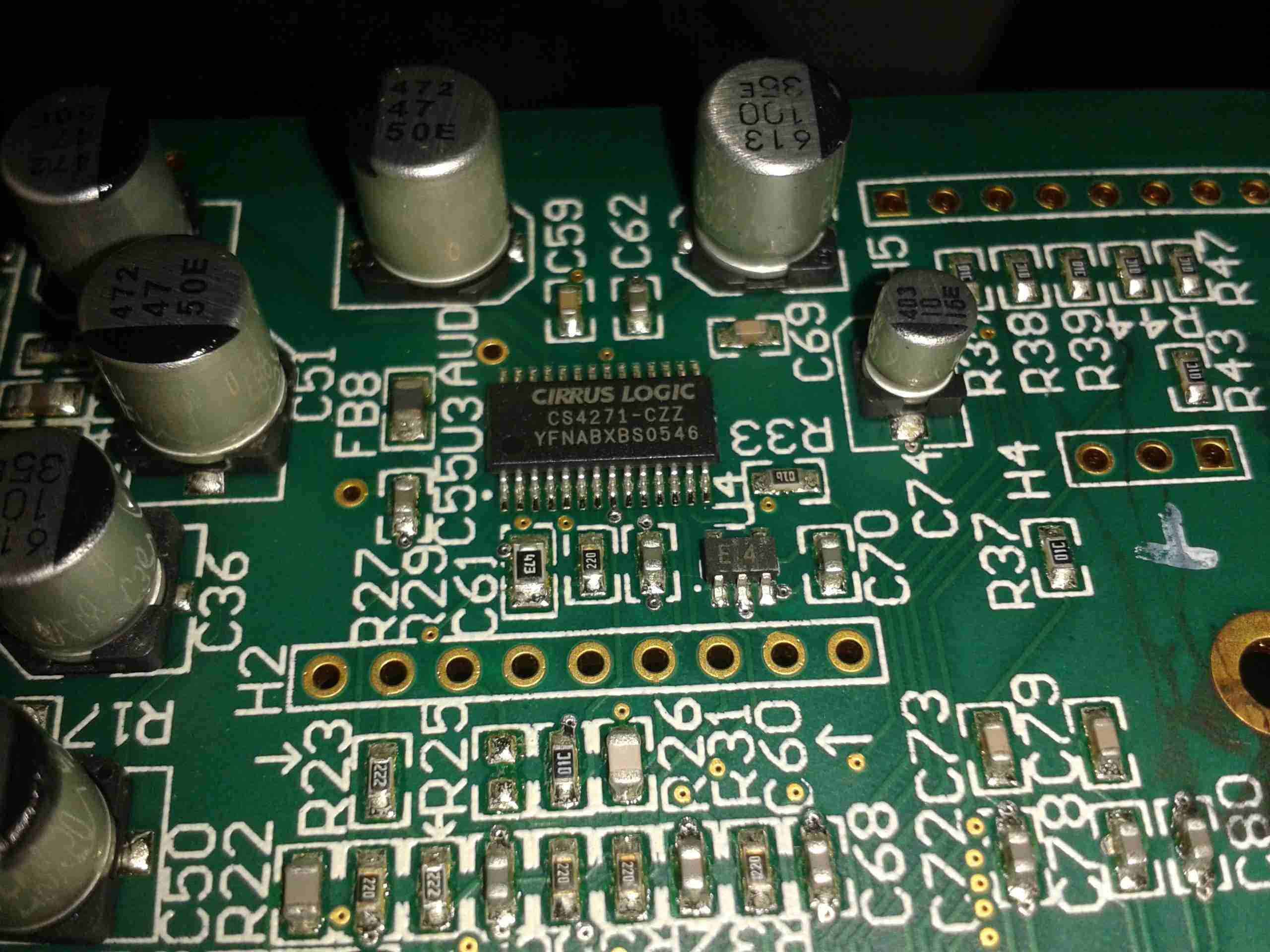
Audio Codec
The audio codec is a CS4271 from Cirrus Logic, a really high quality part, 24-bit resolution, 192kHz Stereo codec. Considering this is for telephone & PA systems that aren’t that high fidelity, it’s well built!
On the boat I have installed custom LED lighting almost everywhere, but we still use CFL bulbs in a standing lamp since they have a wide light angle, and brightness for the size.
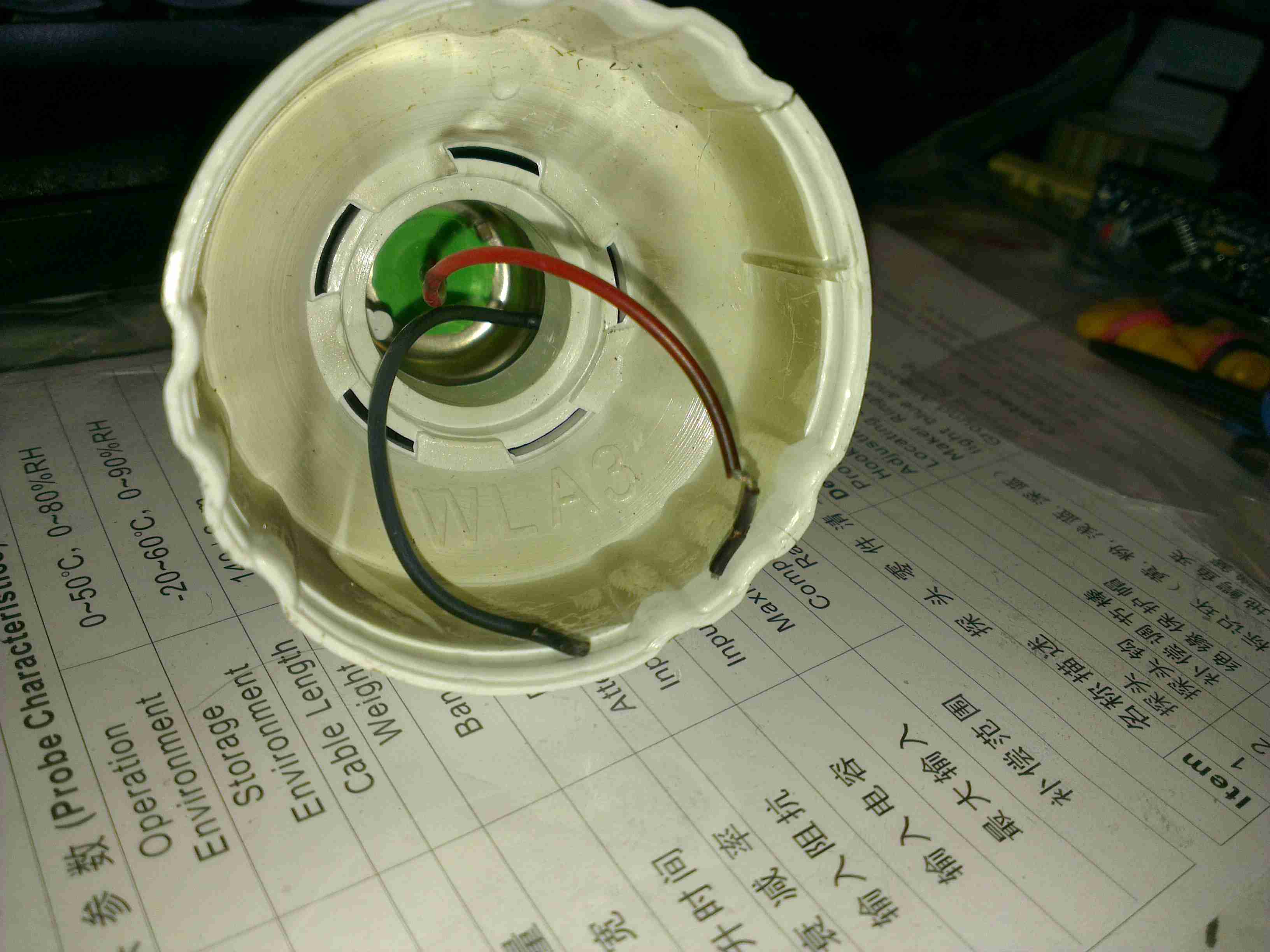
I bought a couple of 12v CFLs from China, and the first of these has been running for over a year pretty much constantly without issue. However, recently it stopped working altogether.
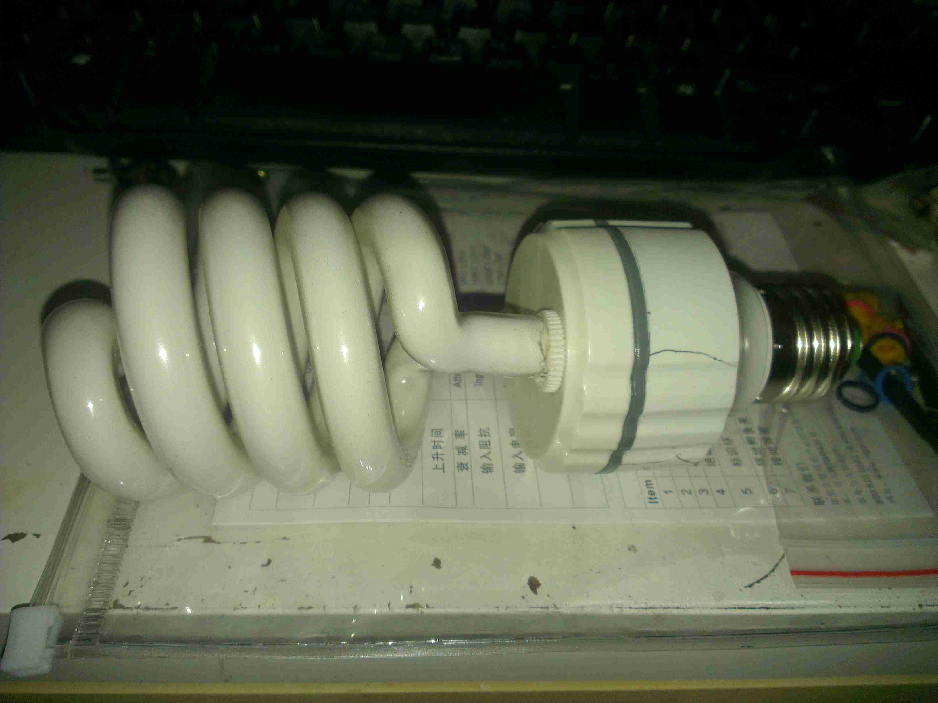
12v CFL
Here’s the lamp, exactly the same as the 240v mains versions, except for the design of the electronic ballast in the base. As can be seen here, the heat from the ballast has degraded the plastic of the base & it’s cracked. The tube itself is still perfectly fine, there are no dark spots around the ends caused by the electrodes sputtering over time.
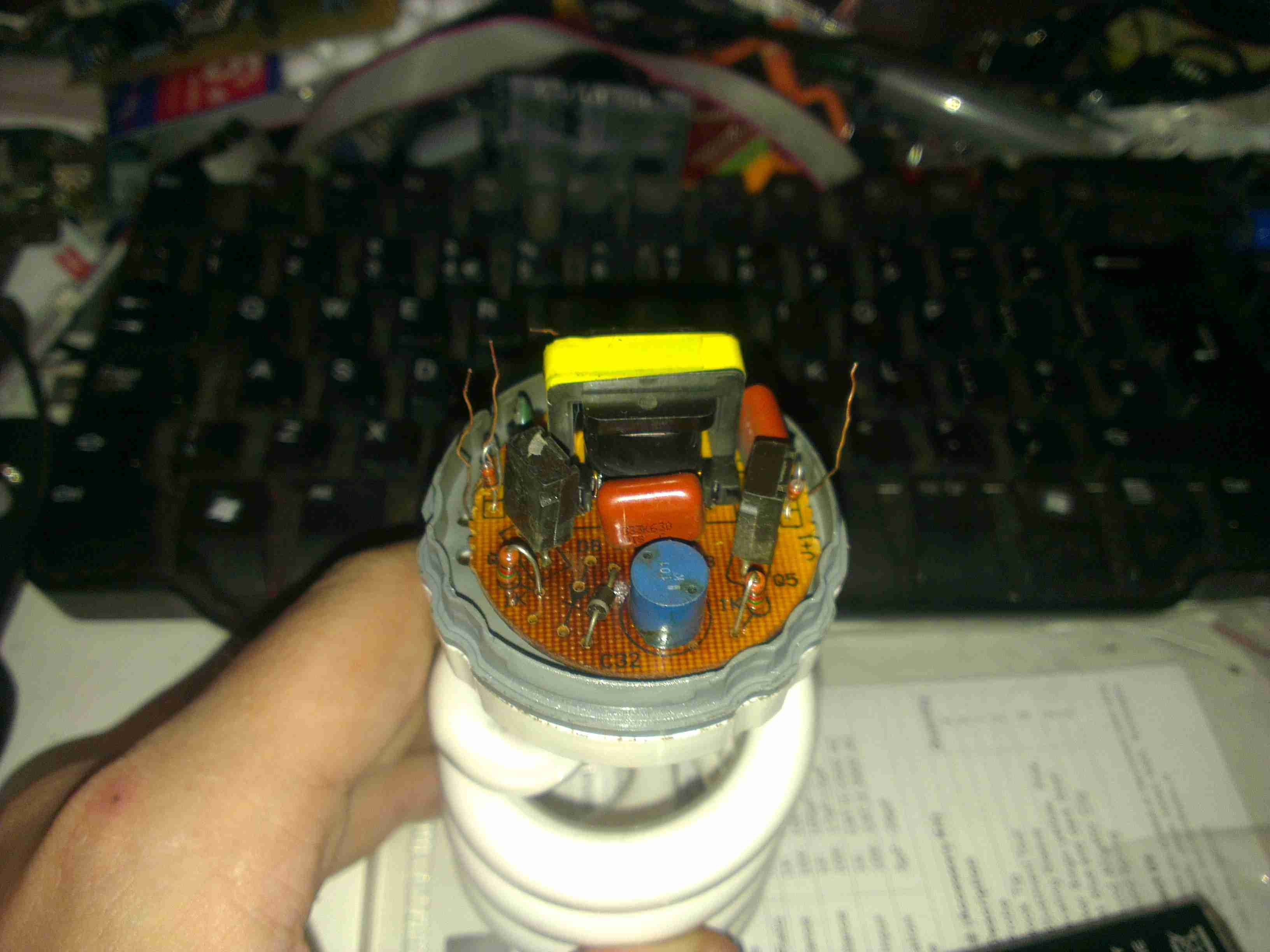
Ballast
Here’s the ballast inside the bottom of the lamp, a simple 2-transistor oscillator & transformer. The board has obviously got a bit warm, it’s very discoloured!
Failed Wiring
The failure mode in this case was cooked wiring to the screw base. The insulation is completely crispy!
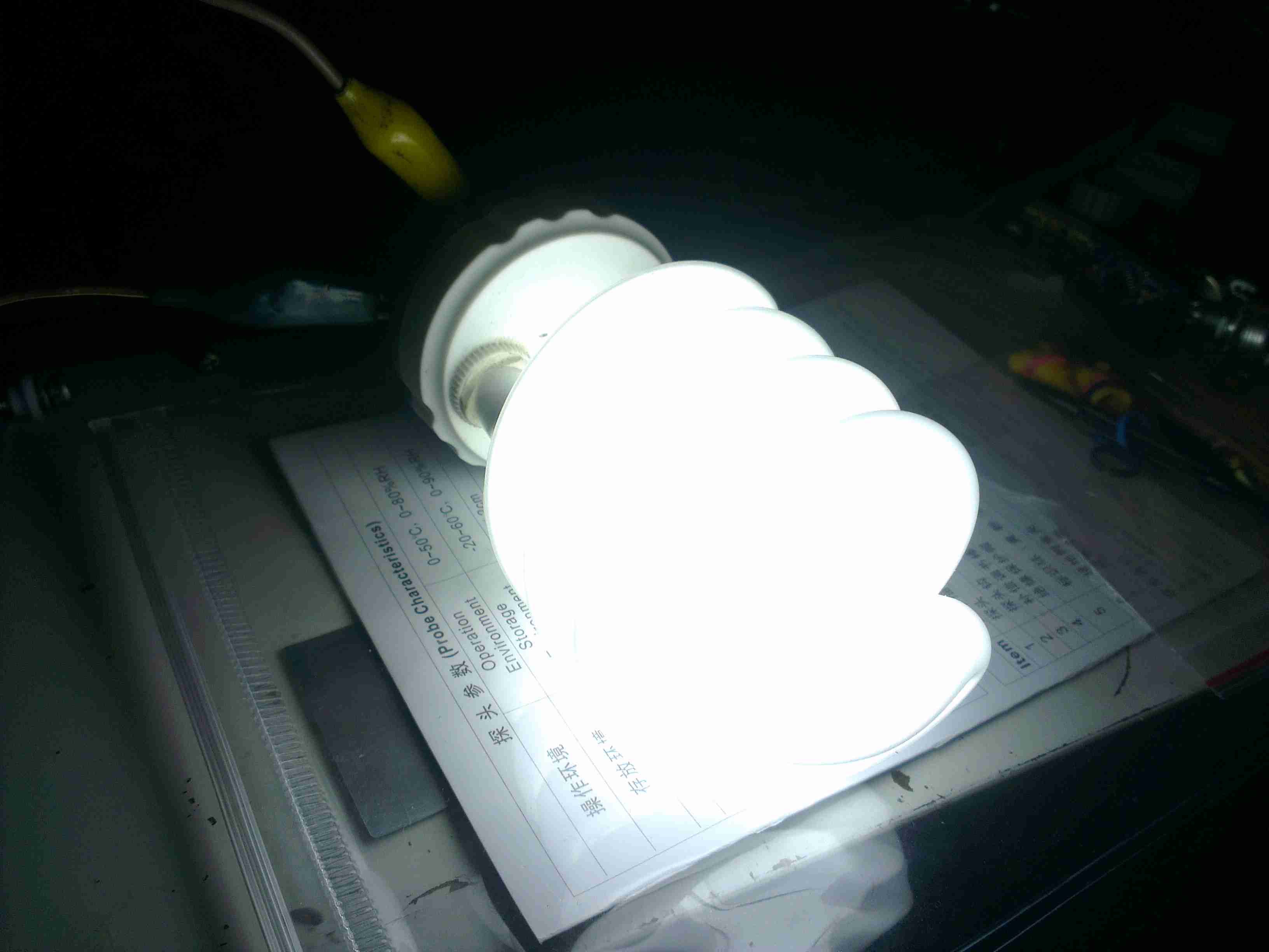
Direct Supply
On connection direct to a 12v supply, the lamp pops into life again! Current draw at 13.8v is 1.5A, giving a power consumption of 20.7W. Most of this energy is obviously being dissipated as heat in the ballast & the tube itself.
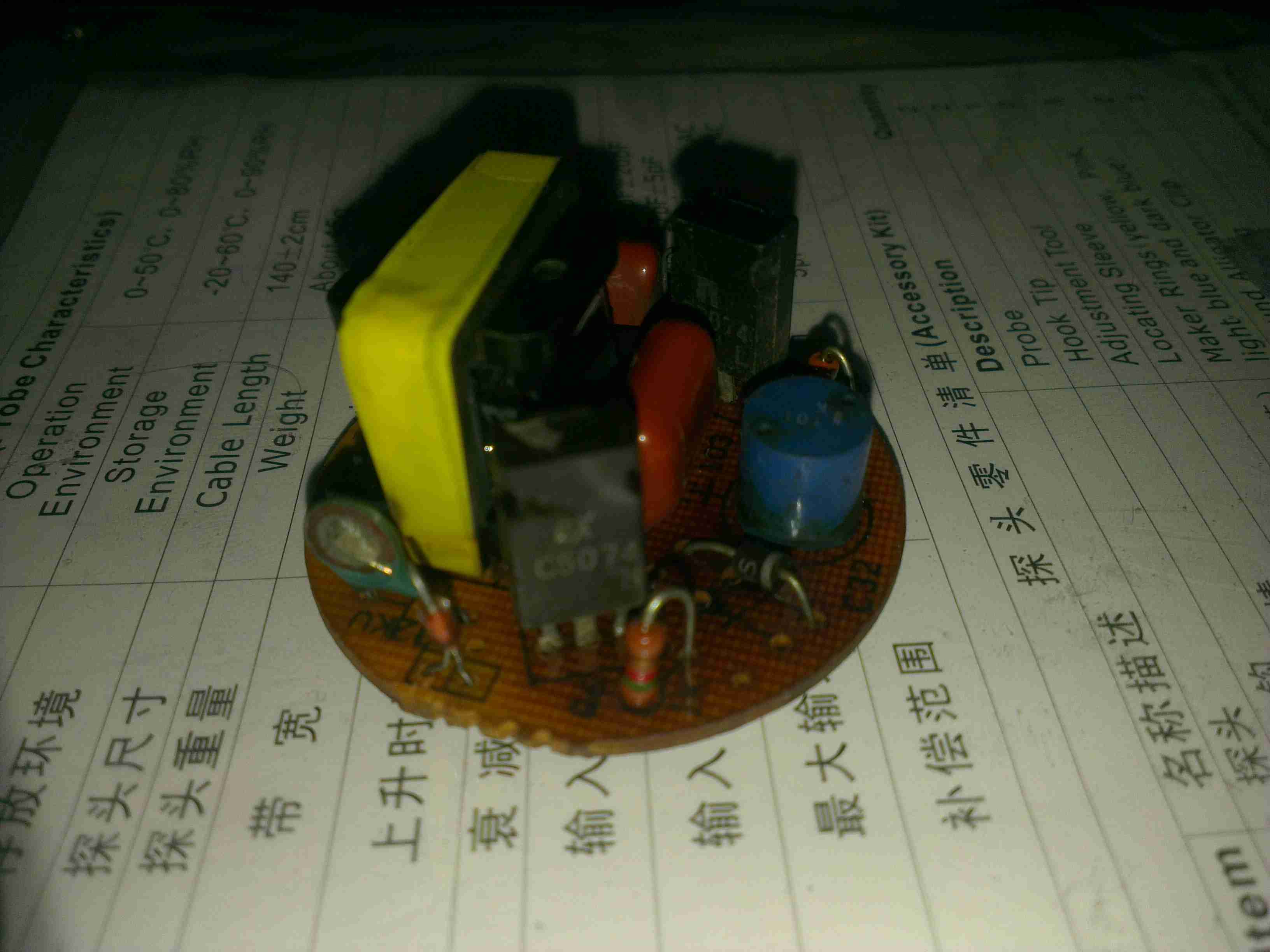
Ballast PCB
Here’s the ballast PCB removed from the case. It’s been getting very warm indeed, and the series capacitor on the left has actually cracked! It’s supposed to be 2.2nF, but it reads a bit high at 3nF. It’s a good thing there are no electrolytics in this unit, as they would have exploded long ago. There’s a choke on the DC input, probably to stop RFI, but it doesn’t have much effect.
Supply Waveform
Here’s the waveform coming from the supply, a pretty crusty sinewave at 71.4kHz. The voltage at the tube is much higher than I expected while running, at 428v.
RFI
Holding the scope probe a good 12″ away from the running bulb produces this trace, which is being emitted as RFI. There’s virtually no filtering or shielding in this bulb so this is inevitable.
I often find myself carrying by go bag up to the boat during trips, so I can do some radio. However at 16lbs it’s a pain on public transport. A fixed radio was required! Another Wouxun GK-UV950P was ordered, and the fact that the head unit is detachable from this radio makes a clean install much easier.
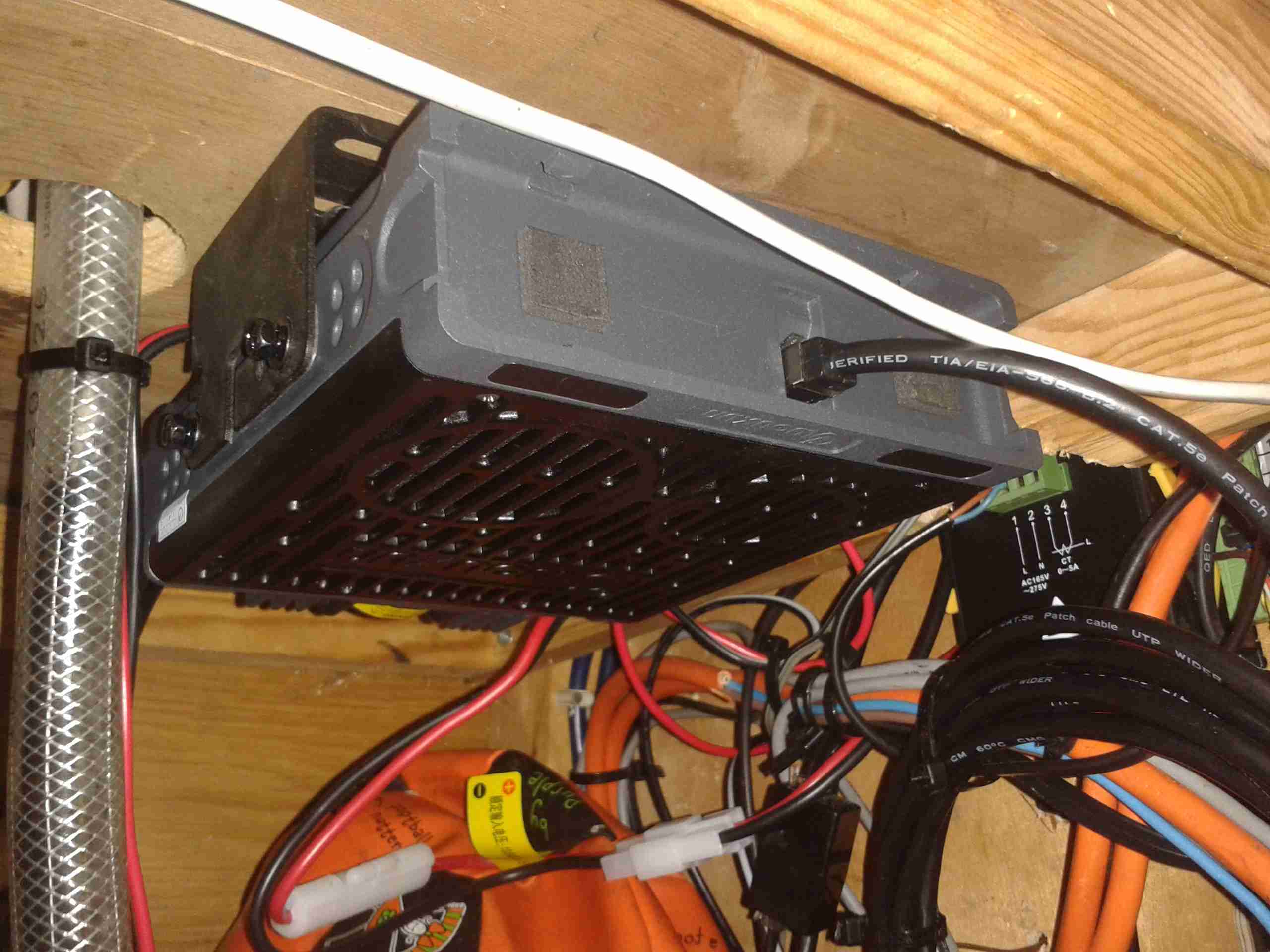
Mounting Bracket
I found a nice spot under a shelf for the main radio unit, above is the mounting bracket installed.
This location is pretty much directly behind where the head unit is placed, but the audio is a bit muffled by the wooden frame of the boat & some external speakers will be required for the future.
Main Radio Unit
Here’s the main radio unit mounted on it’s bracket, with the speakers facing down to improve the audio slightly. I used the supplied interface cable for the head unit, even though it’s too long. I do have the tools to swage on new RJ-45s, but the stuff is a pain to terminate nicely & I really just couldn’t be bothered. So it’s just coiled up with some ties to keep it tidy. Main power is provided directly from the main DC bus. (880Ah total battery capacity, plus 90A engine alternator, 40A solar capacity).
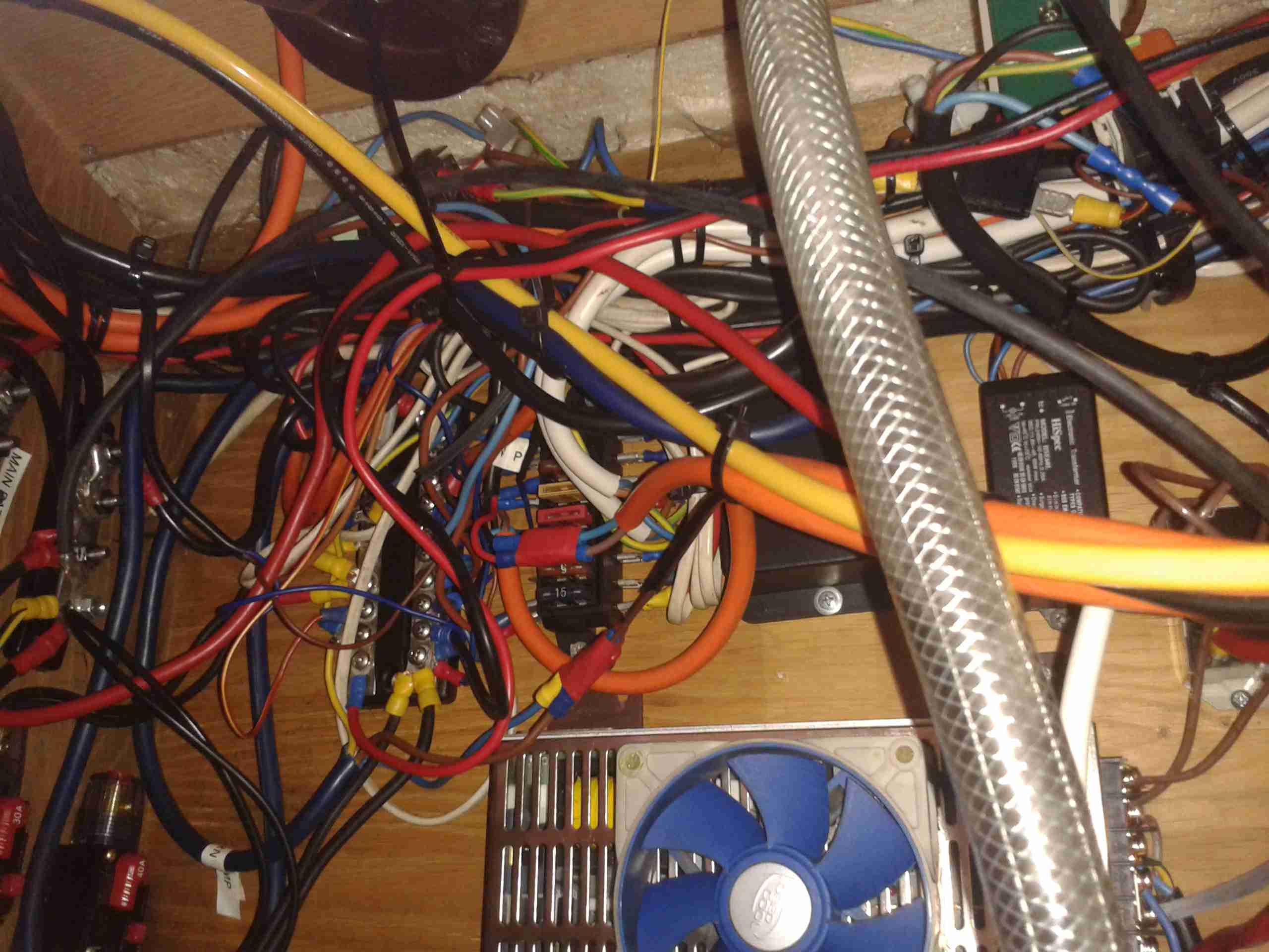
Rat’s Nest
Here’s the main DC bus, with the distribution bars. With the addition of new circuits over the years, this has become a little messy. At some point some labelling would be a good idea!
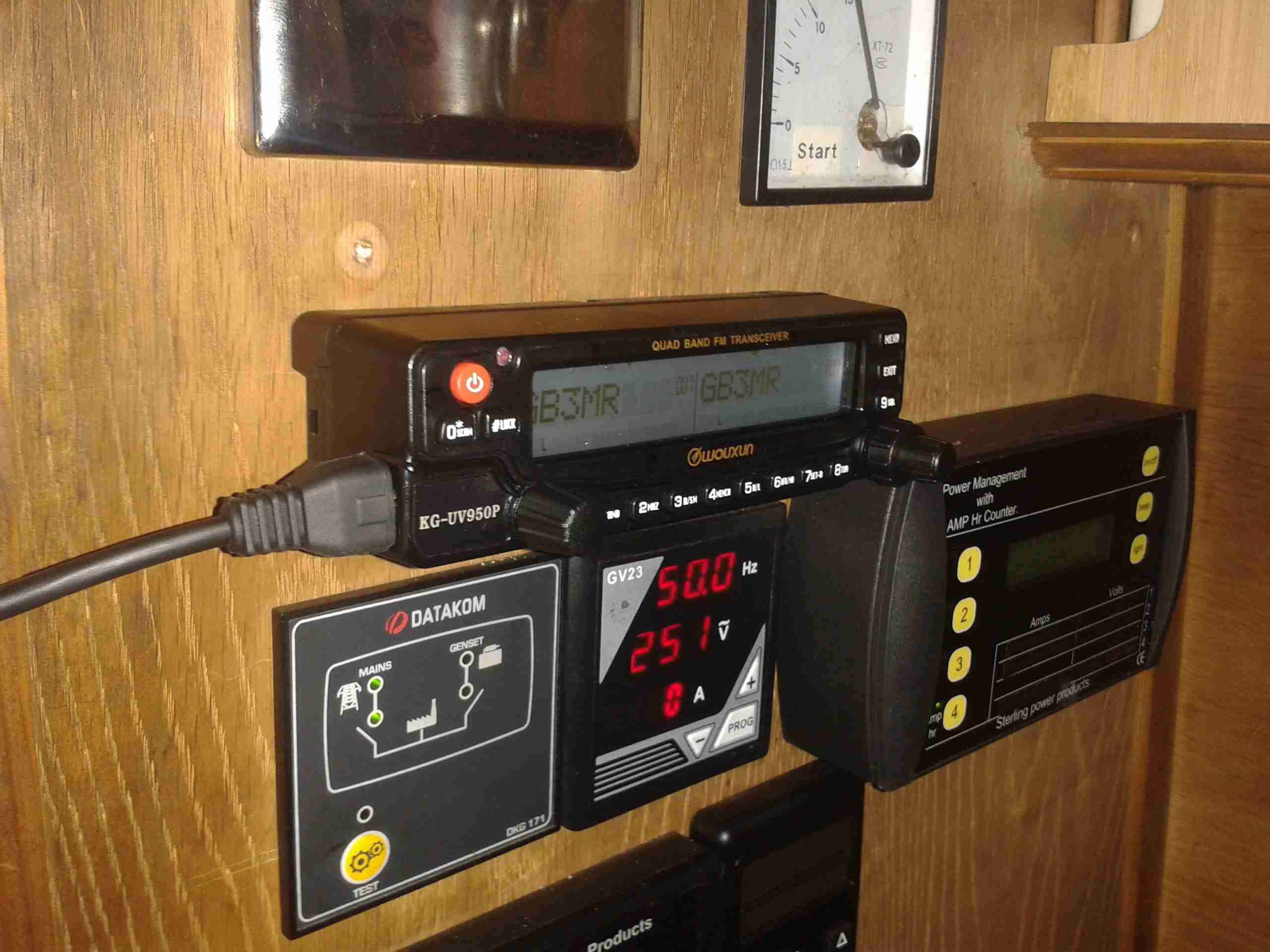
Radio Face Plate
Finally, the head unit is installed in a spot on the main panel. It does stick out a little more than I’d like, but it’s a lot of very dusty work with the router to make a nice hole to sink it further in. All my local repeaters & 2m/70cm simplex are programmed in at the moment.
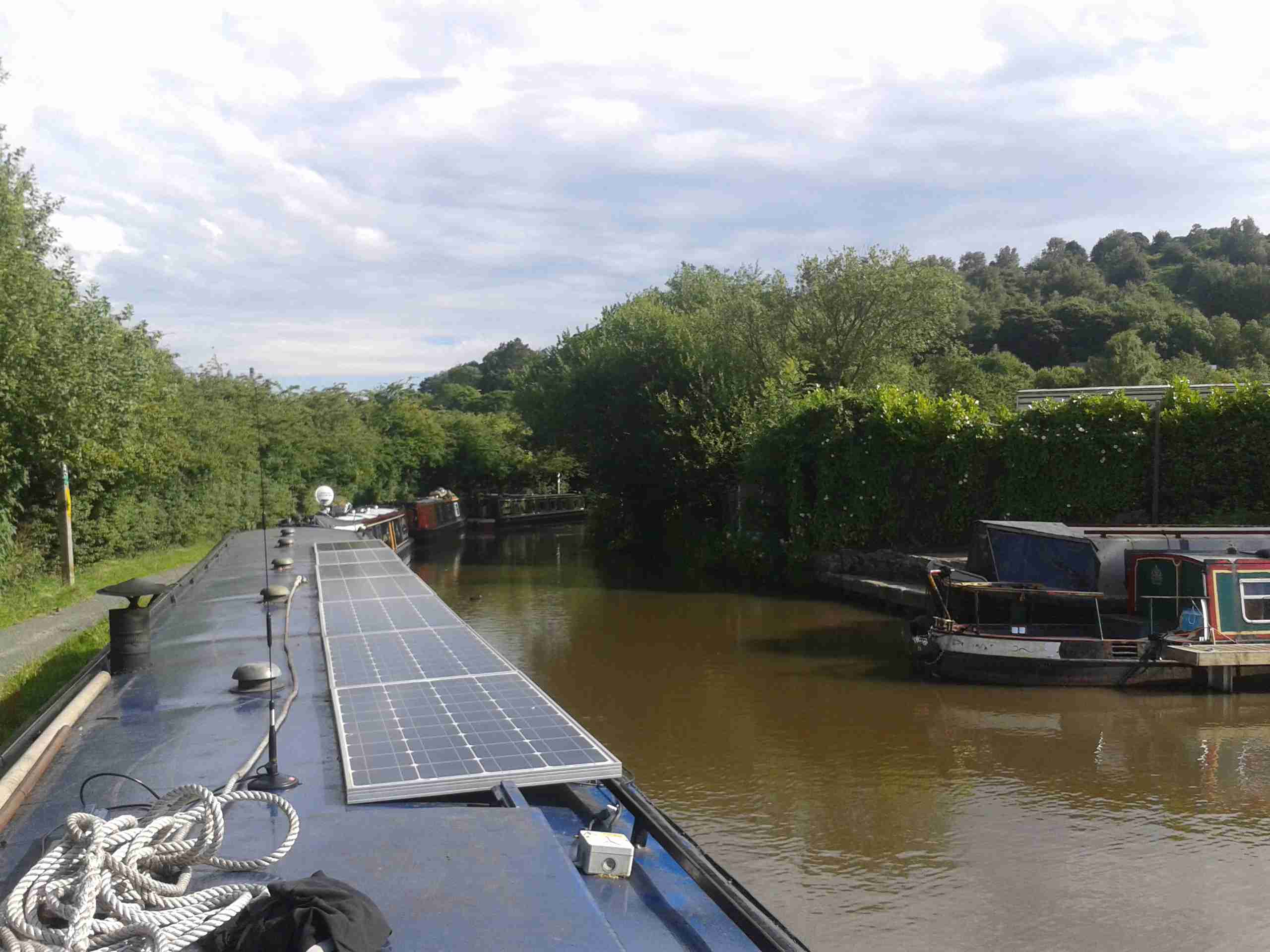
Antenna Magmount
I’ve got a Nagoya SP-80 antenna on a magmount for the radio, a magmount being used due to the many low bridges & trees on the canal. (It’s on the roof next to the first solar panel above). I prefer it to just fall over instead of having the antenna bend if anything hits it!
Part 2 will be coming soon with details of the permanent antenna feeder.
A while ago I blogged about modifying the output voltage of some surplus Cisco switch power supplies to operate at 13.8v.
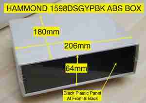
Since I was able to score a nice Hammond 1598DSGYPBK ABS project box on eBay, I’ve built one of the supplies into a nice bench unit.
Hammond ABS CaseSupply Unit
Above is the supply mounted into the box, I had to slightly trim one edge of the PCB to make everything fit, as it was just a couple of mm too wide. Luckily on the mains side of the board is some space without any copper tracks.
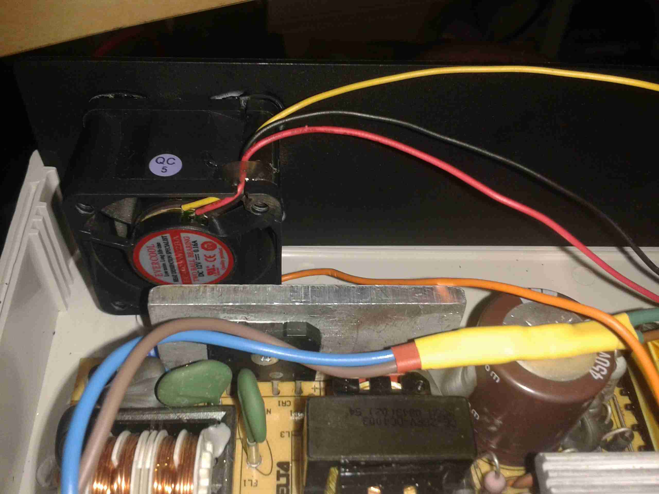
PSU Fan
These supplies are very high quality & very efficient, however they came from equipment that was force-air cooled. Running the PSU in this box with no cooling resulted in overheating. Because of this I have added a small 12v fan to move some air through the case. The unit runs much cooler now. To allow the air to flow straight through the case, I drilled a row of holes under the front edge as vents.
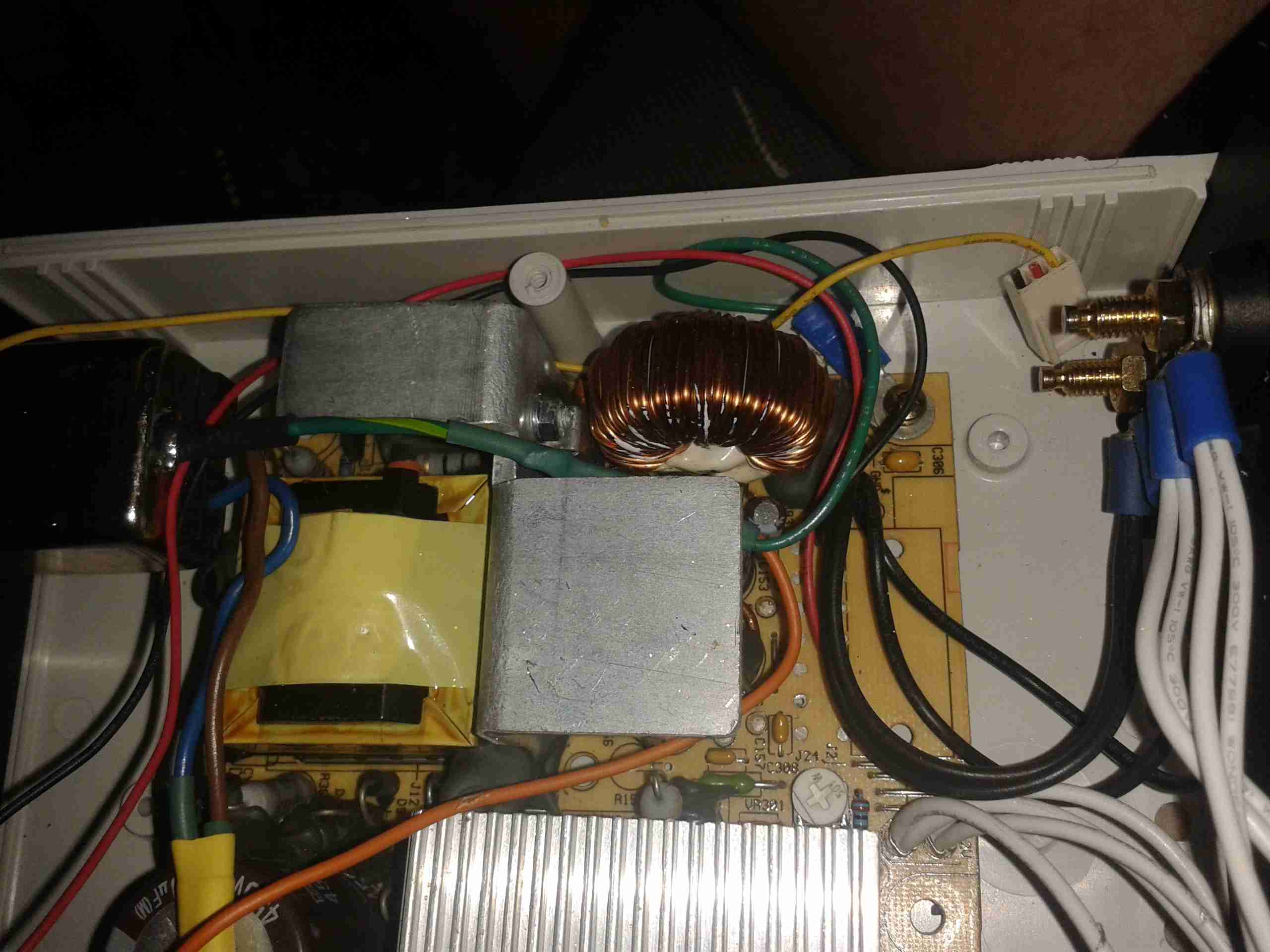
Output Side
Here is the output side of the supply, it uses standard banana jacks for the terminals. I have used crimp terminals here, but they are soldered on instead of crimped to allow for higher current draw. The negative return side of the output is mains earth referenced.
I have tried to measure output ripple on this supply, but with my 10X scope probe, and the scope set to 5mV/Div, the trace barely moves. The output is a very nice & stable DC.
This supply is now running my main radio in the shack, and is small enough to be easily portable when I move my station.
Onboard the boat we have a small issue with a weak TV signal, and this coupled with a 60′ long run of coax is an issue. Due to the loss in the coax, we’ve lost most of the already weak signal.
To try & solve this issue, I’m fitting a masthead amplifier unit.
These amplifiers are fed power down the same coax that’s carrying the RF signal, and a special power supply is supplied with the amplifier for this. However it’s only 240v AC, no 12v version available.
Here’s the power supply unit, which fits into the coax between the TV & the antenna.
Amplifier Supply
Luckily the 240v supply is easily removable & here has been replaced with a 12v regulator.
New Supply
There’s not very much inside the shielding can, just a few filter capacitors & an RF choke on the DC feed, to keep the RF out of the power supply system.
The original cable is used, so the supply doesn’t even look like it’s been modified from the outside.
More to come on this when I get the amplifier installed along with the new coax run 🙂
Recently I decommissioned some networking equipment, and discovered the power supplies in some switches were single rail 12v types, with a rather high power rating. I figured these would be very good for powering my Ham radio gear.
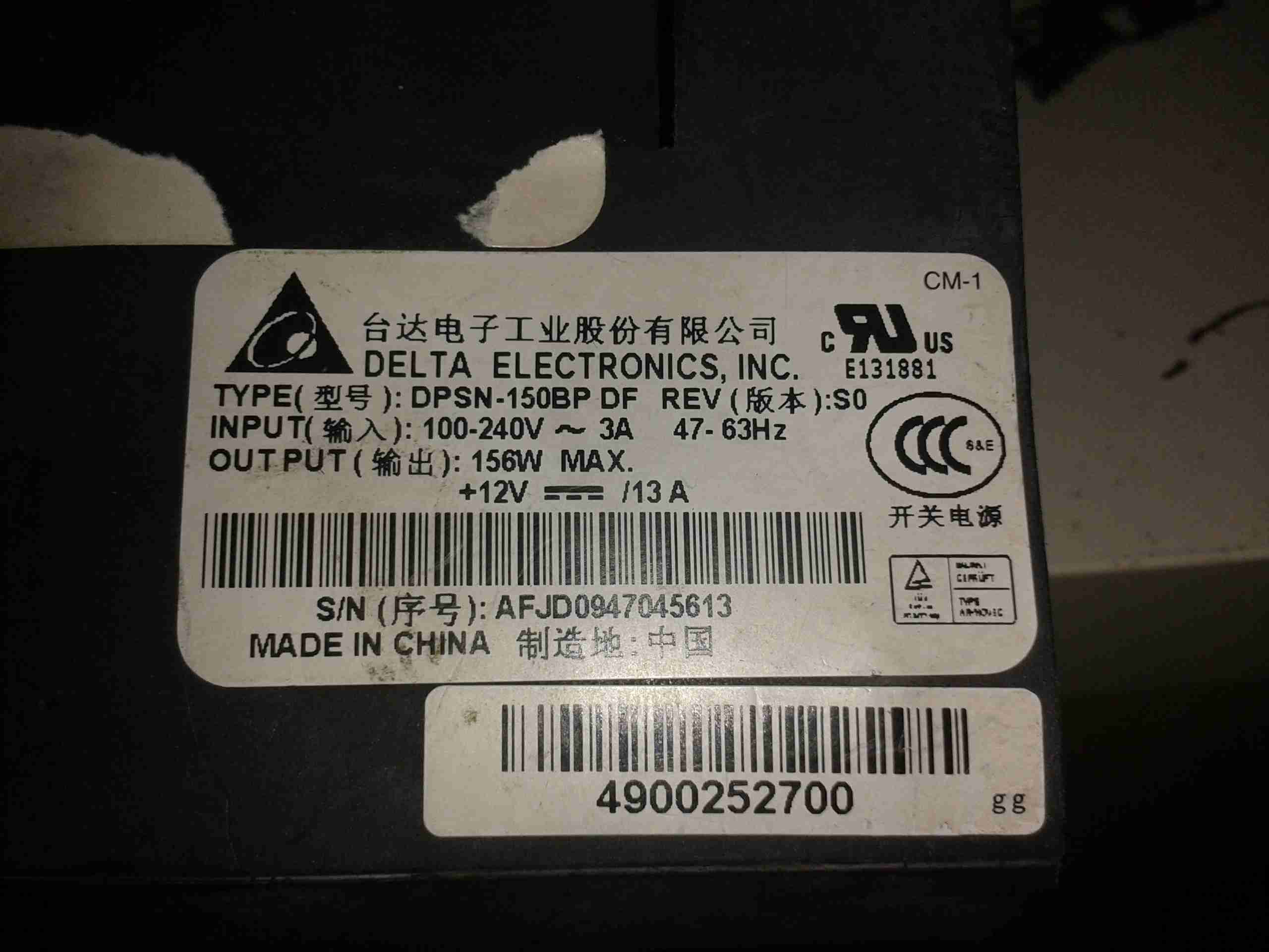
They’re high quality Delta Electronics DPSN-150BP units, rated at a maximum power output of 156W.
Label
These supplies have an adjustment pot for the output voltage regulation, but unfortunately it just didn’t have quite enough range to get from 12.0v to 13.8v. The highest they would go was ~13.04v.
After taking a look at the regulator circuit, I discovered I could further adjust the output voltage by changing a single resistor to a slightly lower value.
Firstly though, a little background on how switched mode power supplies operate & regulate their output voltage.
SMPS
Here’s the supply. It’s mostly heatsink, to cool the large power switching transistors.
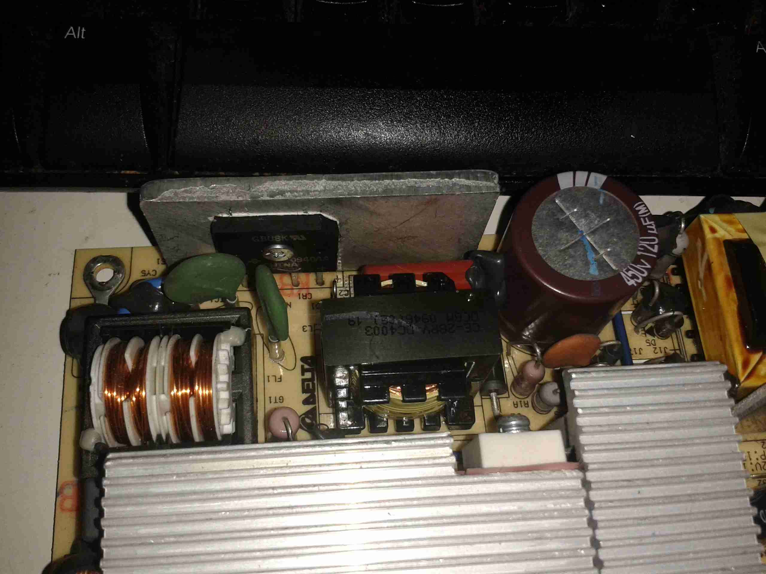
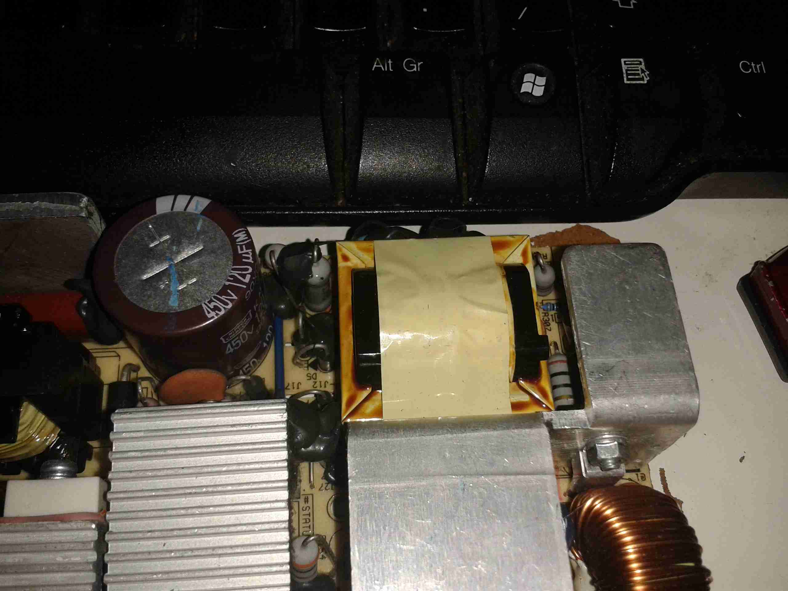
The first thing a SMPS does, is to rectify the incoming mains AC with a bridge rectifier. This is then smoothed by a large electrolytic capacitor, to provide a main DC rail of +340v DC (when on a 240v AC supply).
Mains Input
Above is the mains input section of the PSU, with a large common-mode choke on the left, bridge rectifier in the centre, and the large filter capacitor on the right. These can store a lot of energy when disconnected from the mains, and while they should have a discharge resistor fitted to safely drain the stored energy, they aren’t to be relied on for safety!
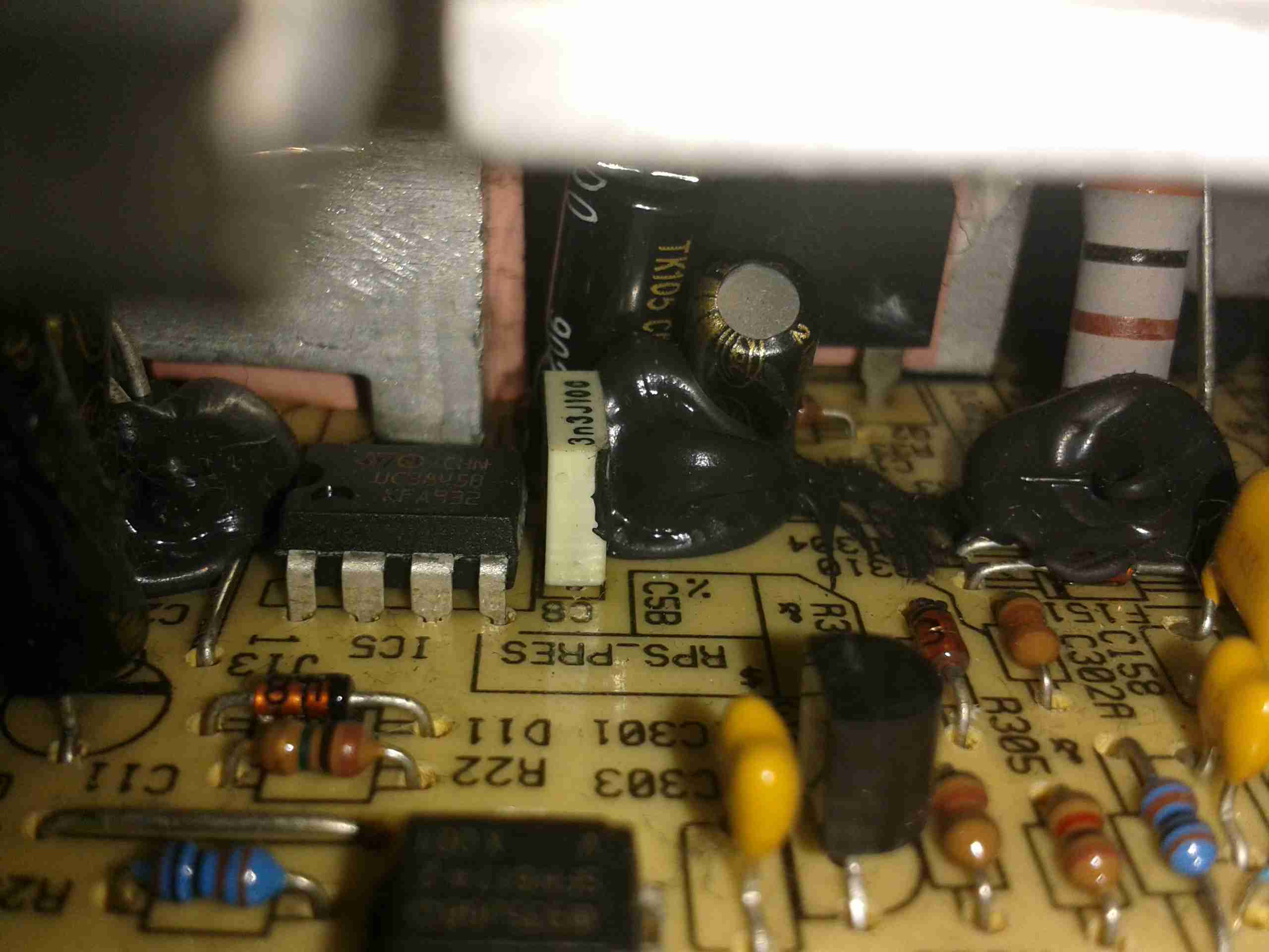
Once the supply has it’s main high voltage DC rail, this is switched into the main transformer by a pair of very large transistors – these are hidden from view on the large silver heatsinks at the bottom of the image. These transistors are themselves driven with a control IC, in the case of this supply, it’s a UC3844B. This IC is hidden under the large heatsink, but is just visible in the below photo. (IC5).
Control ICMain Switching Transformer
Here’s the main switching transformer, these can be much smaller than a conventional transformer due to the high frequencies used. This supply operates at 500kHz.
After the main transformer, the output is rectified by a pair of Schottky diodes, which are attached to the smaller heatsink visible below the transformer, before being fed through a large toroidal inductor & the output filter capacitors.
All this filtering on both the input & the output is required to stop these supplies from radiating their operating frequency as RF – a lot of cheap Chinese switching supplies forego this filtering & as a result are extremely noisy.
After all this filtering the DC appears at the output as usable power.
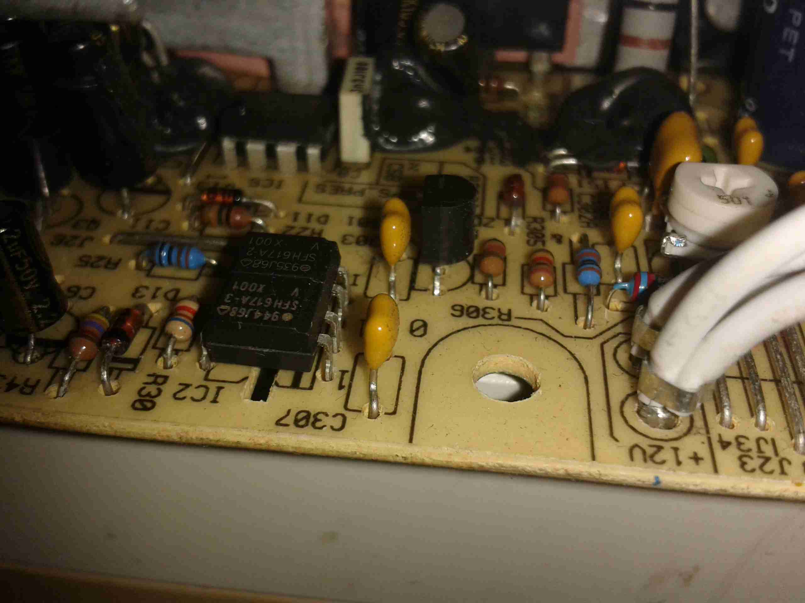
Getting back to regulation, these supplies read the voltage with a resistor divider & feed it back to the mains side control IC, through an opto-isolator. (Below).
Feedback Loop
The opto isolators are the black devices at the front with 4 pins.
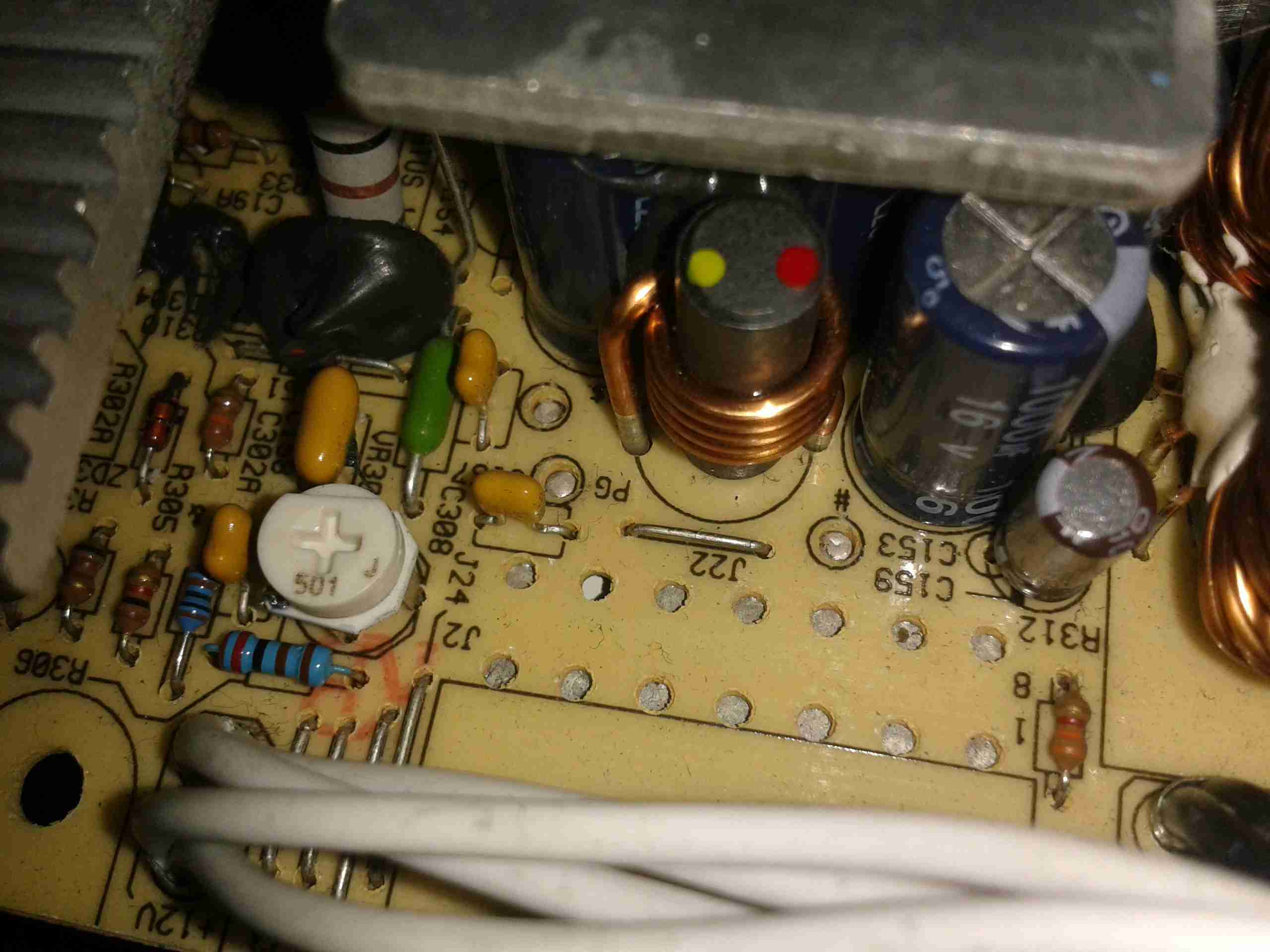
Regulator Adjustment
For a more in-depth look at the inner workings of SMPS units, there’s a good article over on Hardware Secrets.
My modification is simple. Replacing R306 (just below the white potentiometer in the photo), with a slightly smaller resistor value, of 2.2KΩ down from 2.37KΩ, allows the voltage to be pulled lower on the regulator. This fools the unit into applying more drive to the main transformer, and the output voltage rises.
It’s important to note that making too drastic a change to these supplies is likely to result in the output filter capacitors turning into grenades due to overvoltage. The very small change in value only allows the voltage to rise to 13.95v max on the adjuster. This is well within the rating of 16v on the output caps.
Now the voltage has been sucessfully modified, a new case is on the way to shield fingers from the mains. With the addition of a couple of panel meters & output terminals, these supplies will make great additions to my shack.
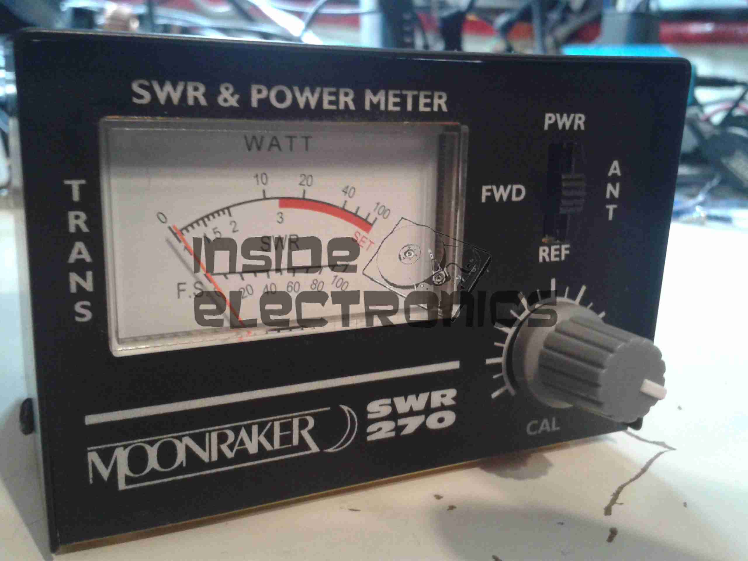
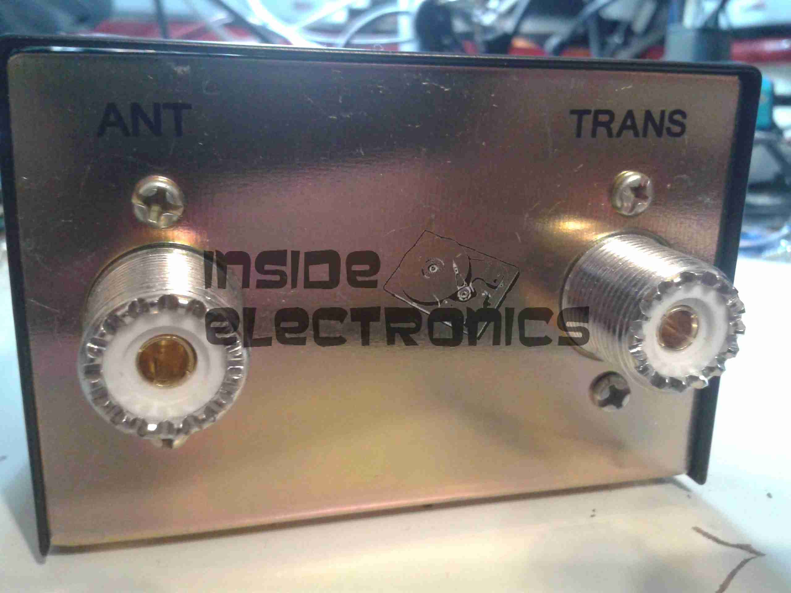
As I’m building up my radio shack, I figured an SWR meter would be a handy addition to my arsenal. This is a cheap Moonraker brand meter, which also will measure RF power. Above the front of the meter is shown, with the moving coil meter movement on the left, calibration adjustment on the right & the forward/reverse power switch.
Meter Rear
For connections, standard SO-259 jacks are provided. The casing is sturdy 1mm steel. This is good, considering it’ll probably take a beating in my portable radio bag.
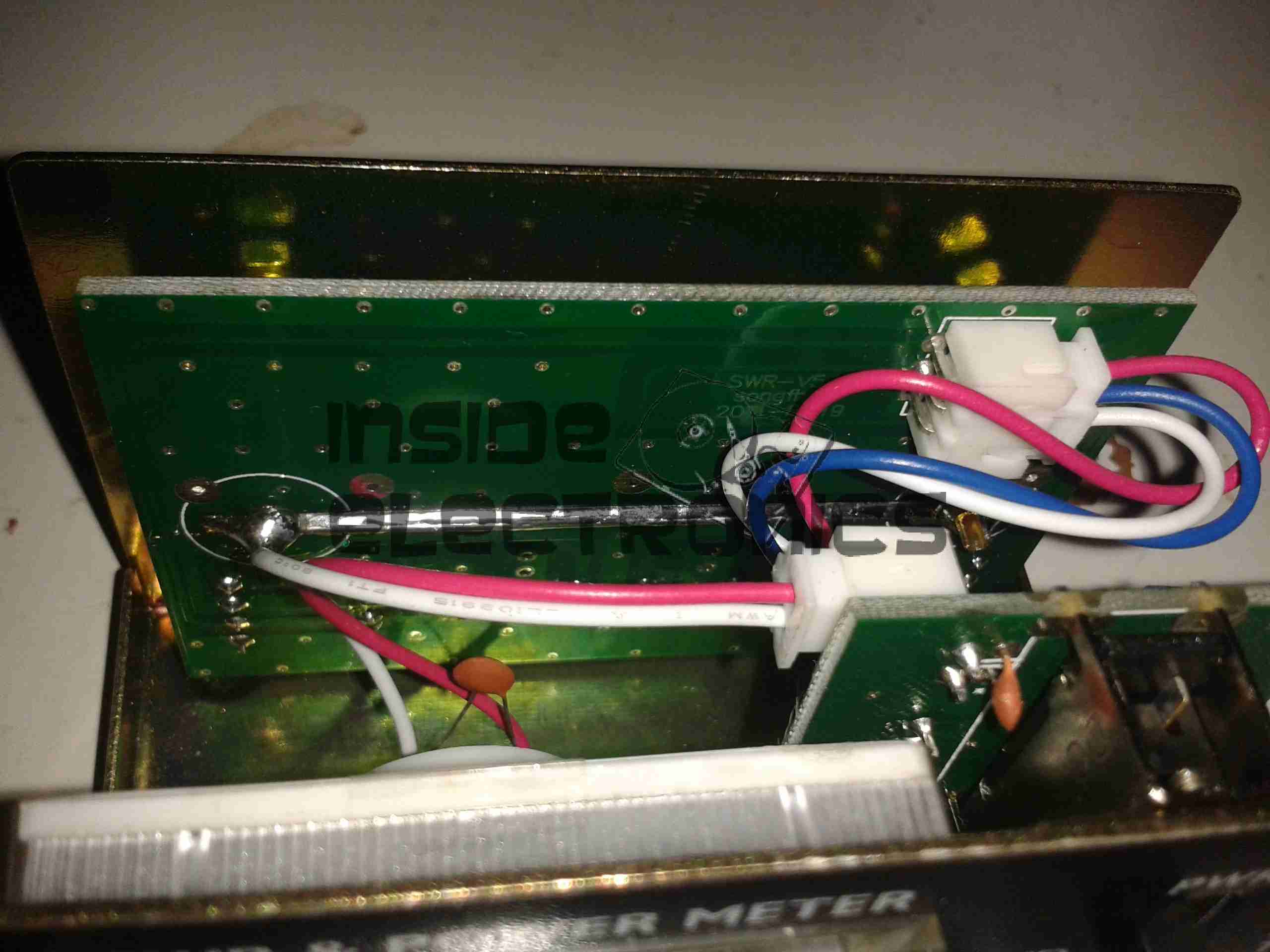
Directional Coupler PCB
Here the cover is removed, showing some of the internals. The large PCB across the back is the directional coupler.
Directional Coupler Circuit
The SO-259 connectors are bridged with a transmission line, (the track covered in solder in the image below), while there are a pair of sense lines running alongside. This main line is electromagnetically coupled to the two smaller sense lines, which are terminated at one end with resistors, with diodes at the other to rectify the coupled signal.
The termination resistors are sized to match the impedance of the sense lines.
The diodes, having rectified the coupled RF, produce DC voltages representing the value of the forward & reverse RF power. These DC voltages are smoothed with the capacitors.
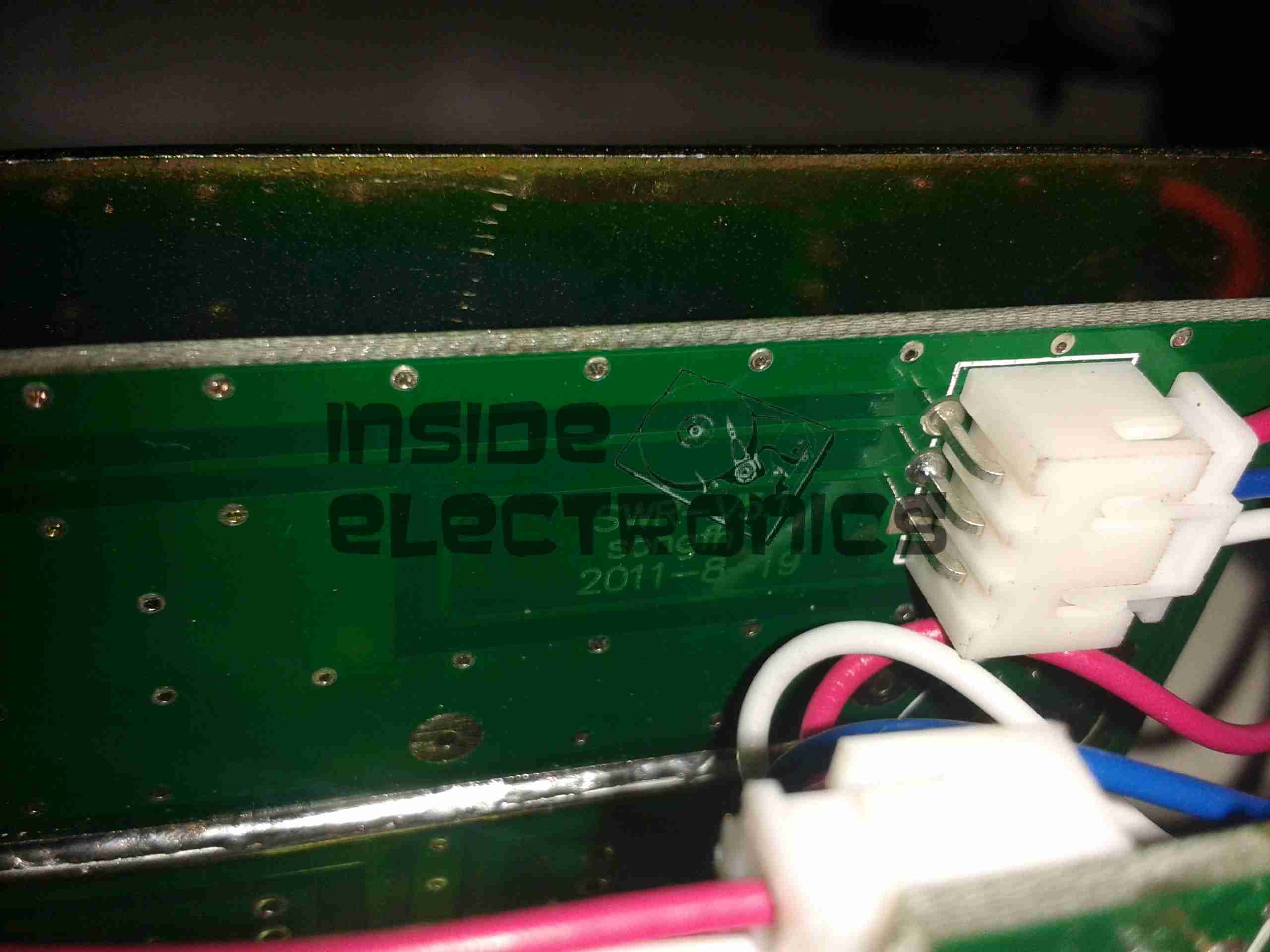
PCB Marking
The PCB is dated 19-8-2011, so it’s a fairly old design.
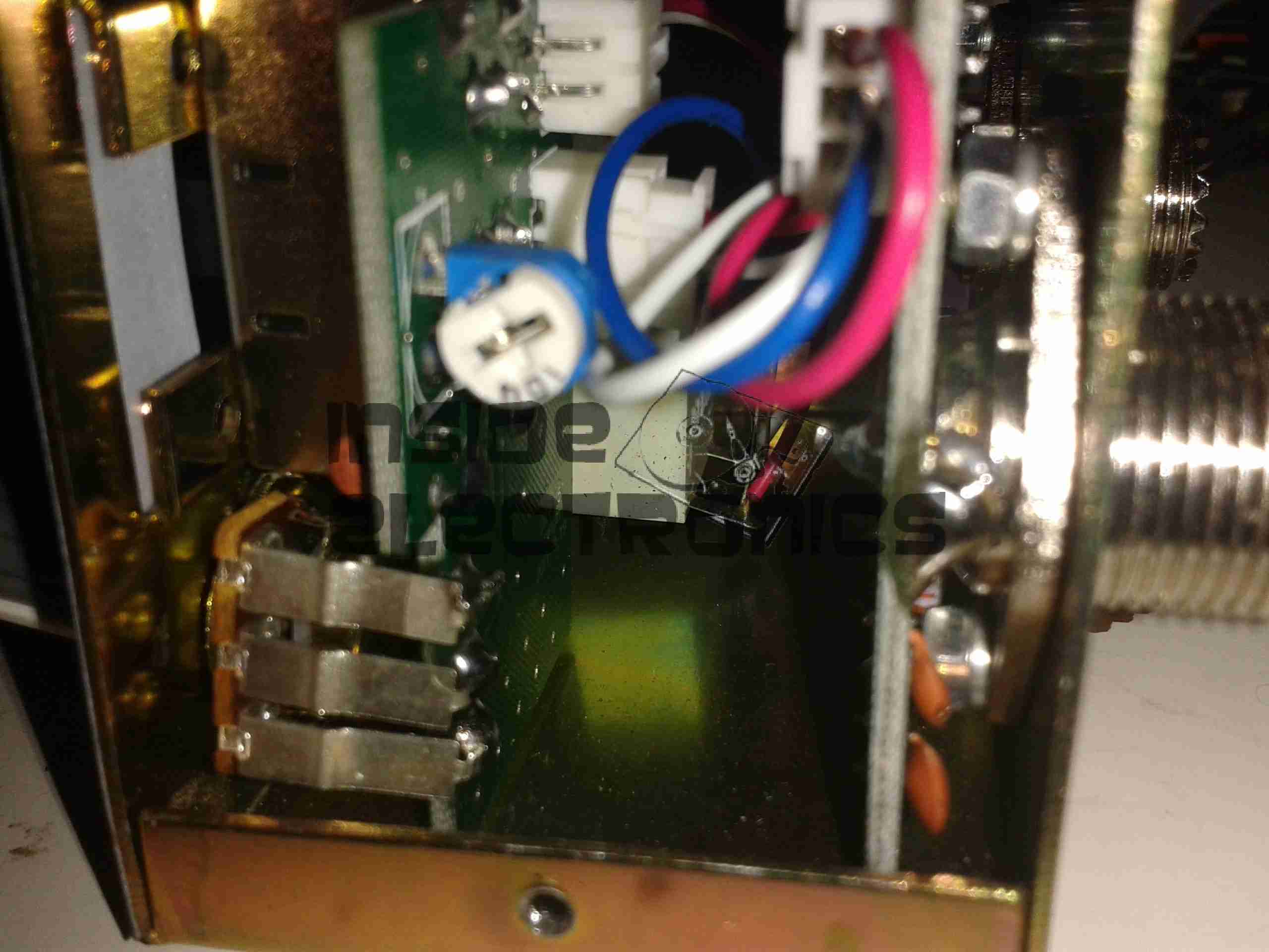
Adjustments
Here is visible the back of the user calibration adjuster, with the factory calibration trimmer.
Meter Movement
Back of the meter movement. This is a standard moving coil type. Nothing special.
This meter will soon be modified to accept connection of an external Arduino-based SWR & power meter, which I can calibrate individually for each band.
Stay tuned for that upcoming project.
I recently managed to score a 3″ B&W portable TV on eBay, a Panasonic TR-3000G. As these old units are now useless, thanks to the switch off of analogue TV signalling, I figured I could find a composite signal internally & drive the CRT with an external source.
Panasonic TR-3000G
Here’s the TV in it’s native state. Running from 9v DC, or 6 D size cells. I’m guessing from somewhere around the 1970’s. Here is the CRT & associated drive circuitry, removed from the casing:
CRT Module
After dissecting the loom wiring between the CRT board & the RF/tuner board, I figured out I had to short out Pins 1,2 & 5 on the H header to get the CRT to operate straight from the power switch. This board also generates the required voltages & signals to drive the RF tuner section. I have removed the loom from this, as the PCB operates fine without. It doesn’t seem to be fussy about power input either: it’s specified at 9v, but seems to operate fine between 7.5v & 14.5v DC without issue.
Video Connections
Tracing the wiring from the tuner PCB revealed a length of coax snaking off to the section marked Video/Sync. I successfully found the composite input!
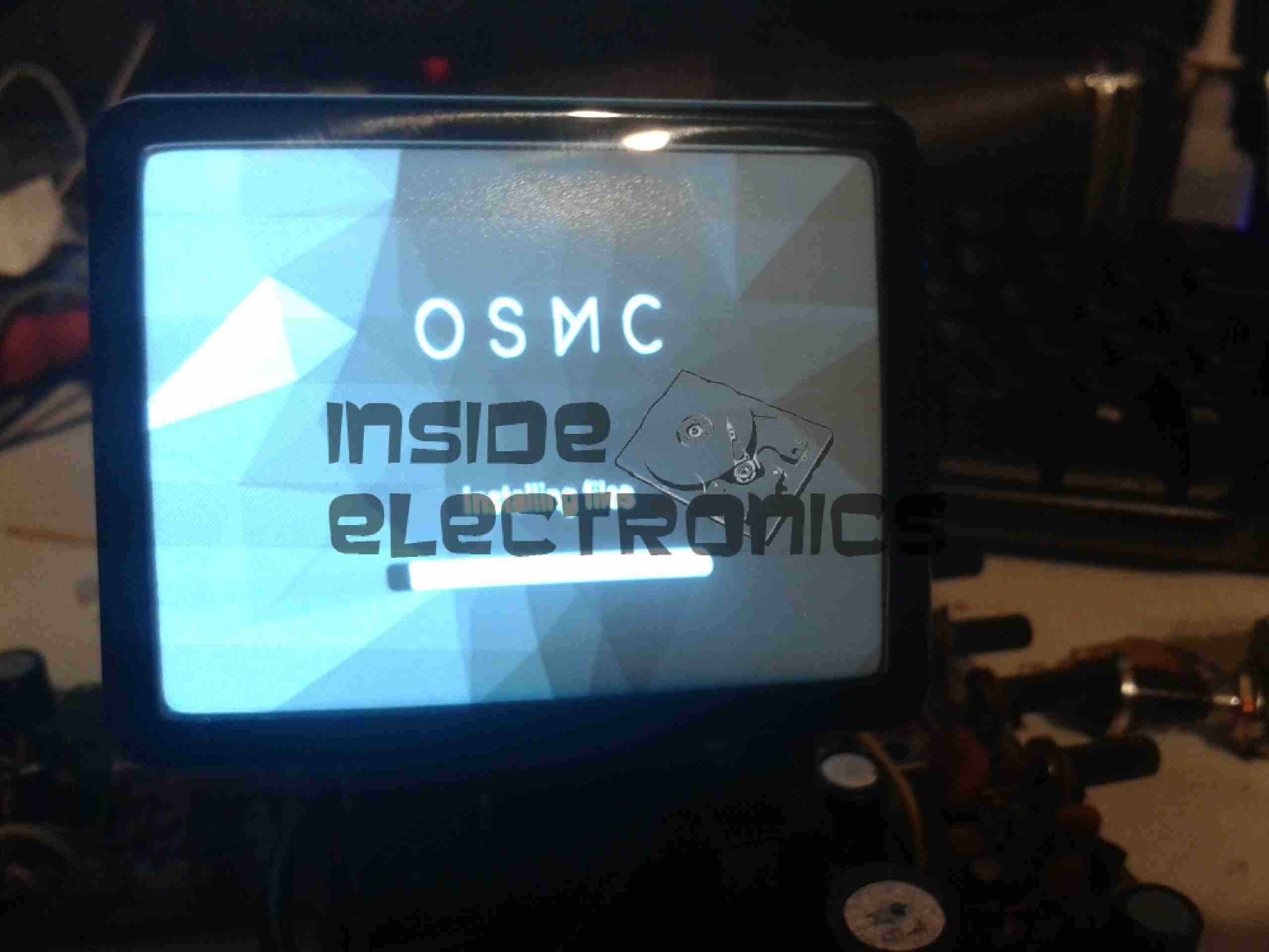
Running OSMC
A quick bit of wiring to a Raspberry Pi, & we have stable video! For such an old unit, the picture quality is brilliant, very sharp focus.
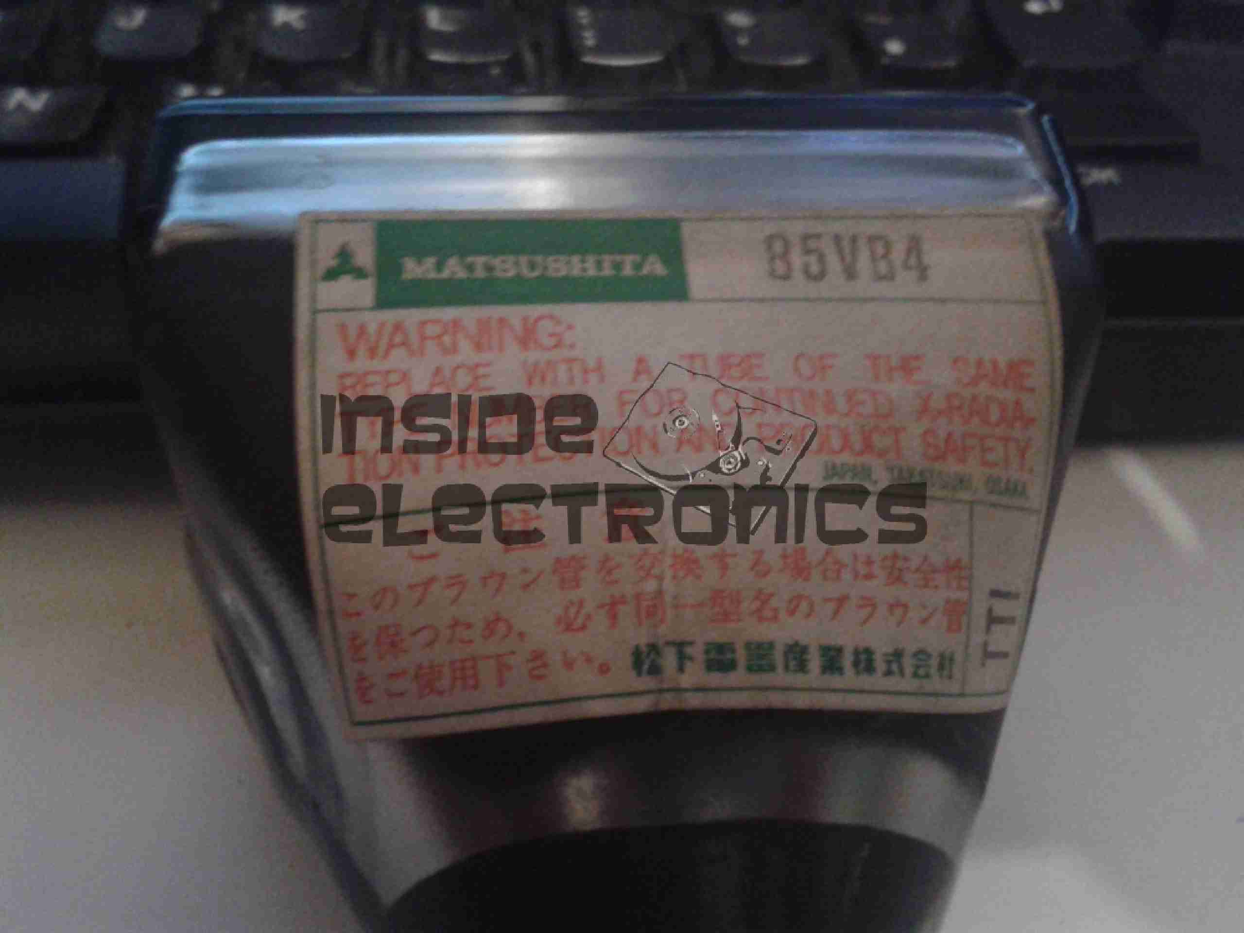
Matsushita 85VB4 CRT
Closeup of the CRT itself. I haven’t been able to find much data on this unit, but I’m guessing it’s similar to many commercial viewfinder CRTs.
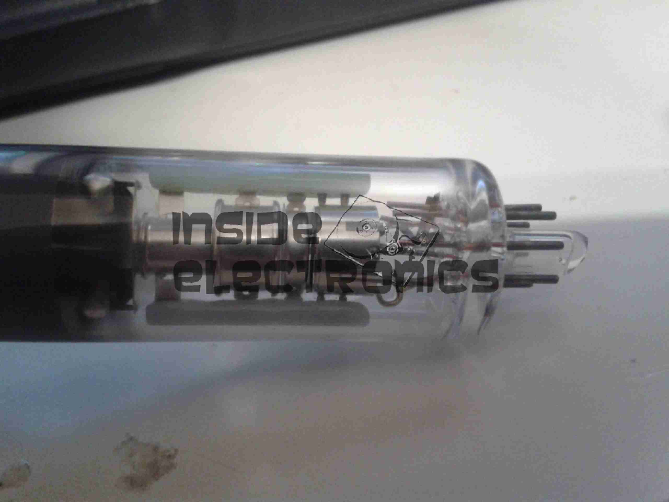
Electron Gun Closeup
Amazingly, there isn’t a single IC in the video circuitry, it’s all discrete components. This probably accounts for the large overall size of the control PCB. Viewfinder CRTs from a few years later on are usually driven with a single IC & a few passives that provide all the same functions.
It’s official. I’m now part of the uRadMonitor network, & assisting in some of the current issues with networking some people (including myself) have been having.
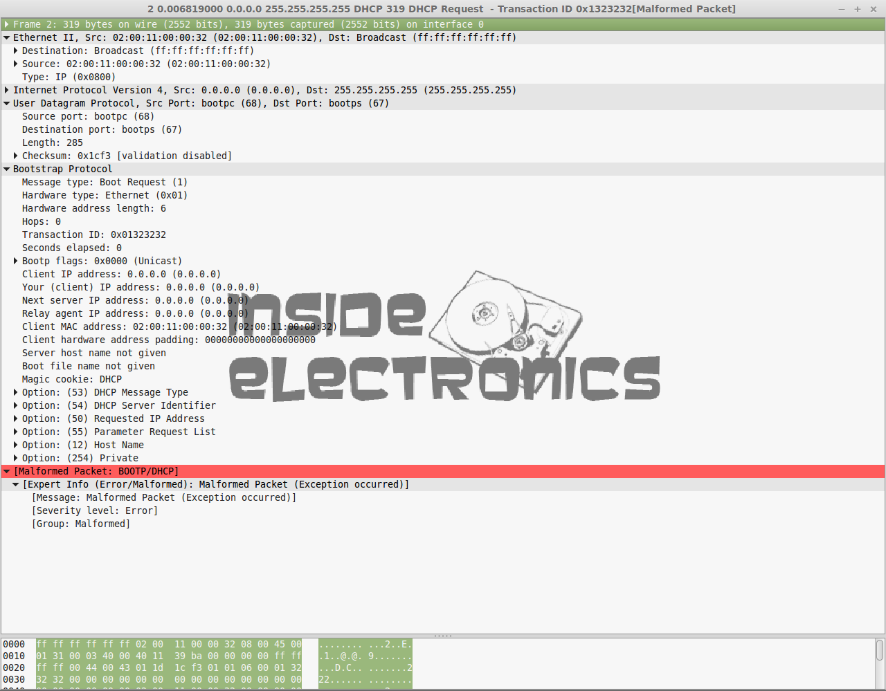
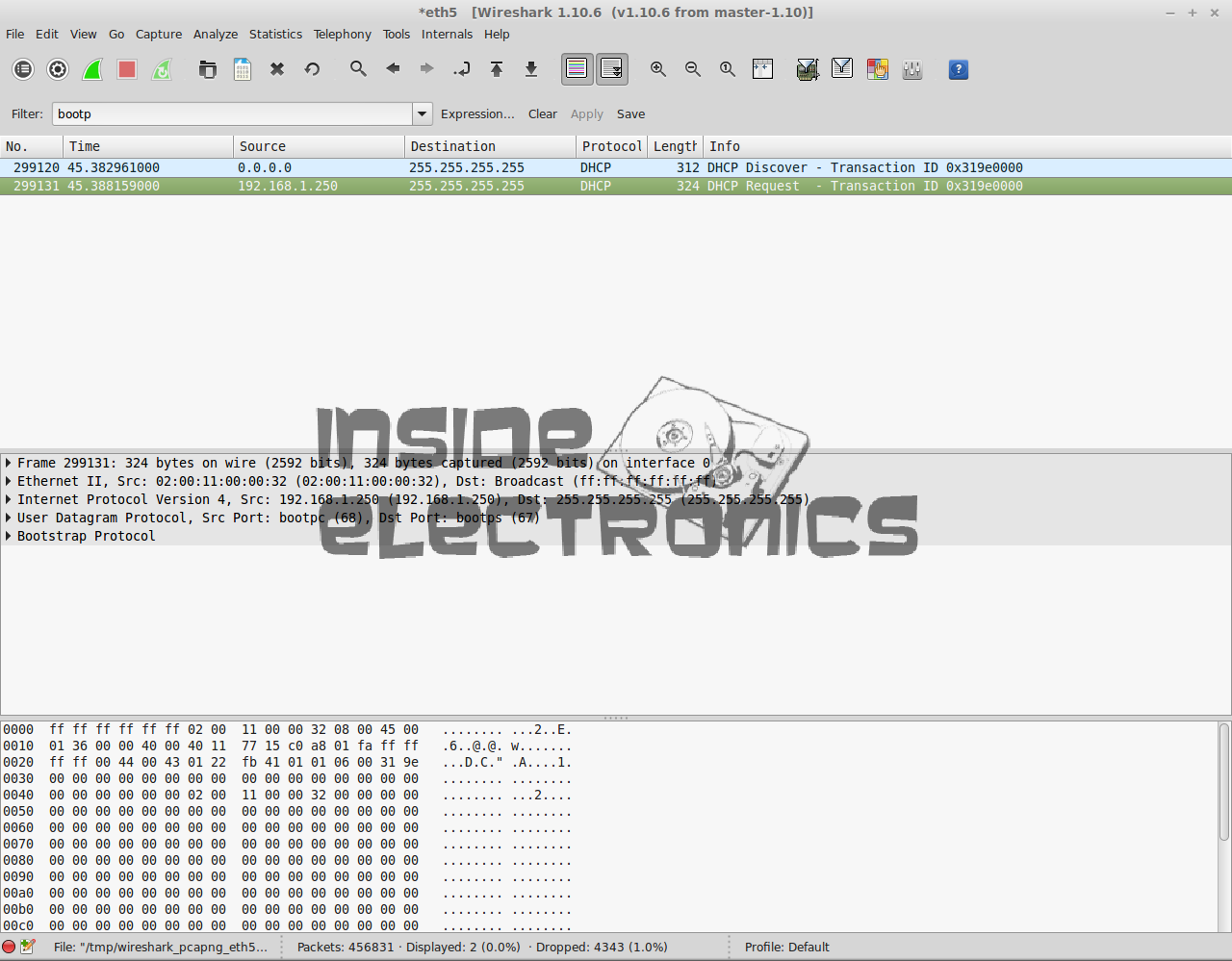
It seems that the uRadMonitor isn’t sending out technically-valid DHCP requests, here is what Wireshark thinks of the DHCP on my production network hardware setup:
WireShark Screencap
As can be seen, the monitor unit is sending a DHCP request of 319 bytes, where a standard length DHCP Request packet should be ~324 bytes, as can be seen on the below screen capture.
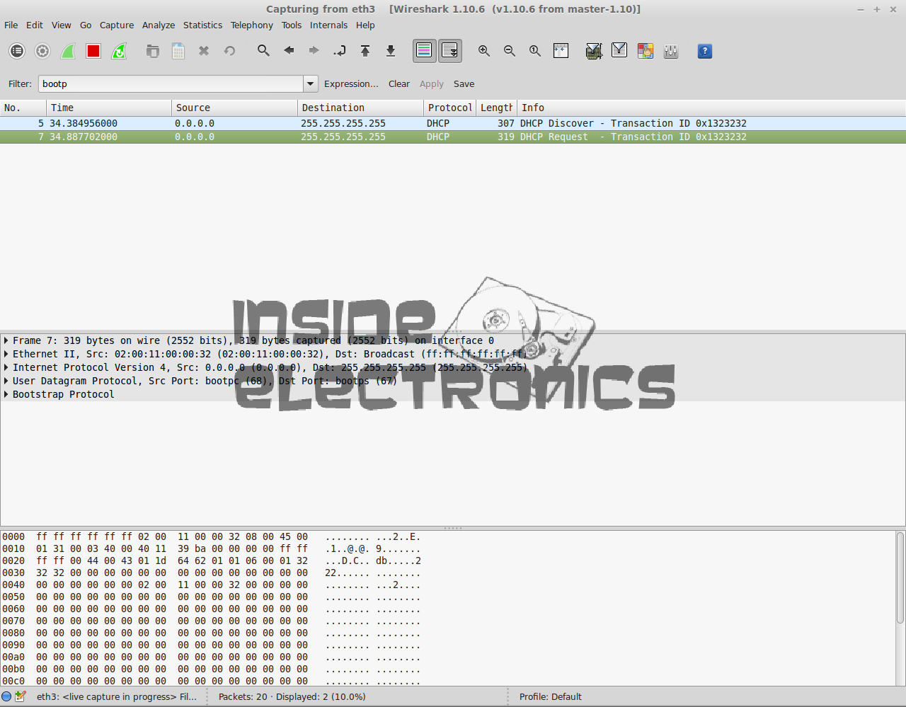
Valid DHCP
This valid one was generated from the same SPI Ethernet module as the monitor, (Microchip ENC28J60) connected to an Arduino. Standard example code from the EtherCard library was used to set up the DHCP. The MAC address of the monitor was also cloned to this setup to rule out the possibility of that being the root cause.
My deductive reasoning in this case points to the firmware on the monitor being at fault, rather than the SPI ethernet hardware, or my network hardware. Radu over at uRadMonitor is looking into the firmware being at fault.
Strangely, most routers don’t seem to have an issue with the monitor, as connecting another router on a separate subnet works fine, and Wireshark doesn’t even complain about an invalid DHCP packet, although it’s exactly the same.
Working DHCP
As the firmware for the devices isn’t currently available for me to pick apart & see if I can find the fault, it’s up to Radu to get this fixed at the moment.
Now, for a µTeardown:
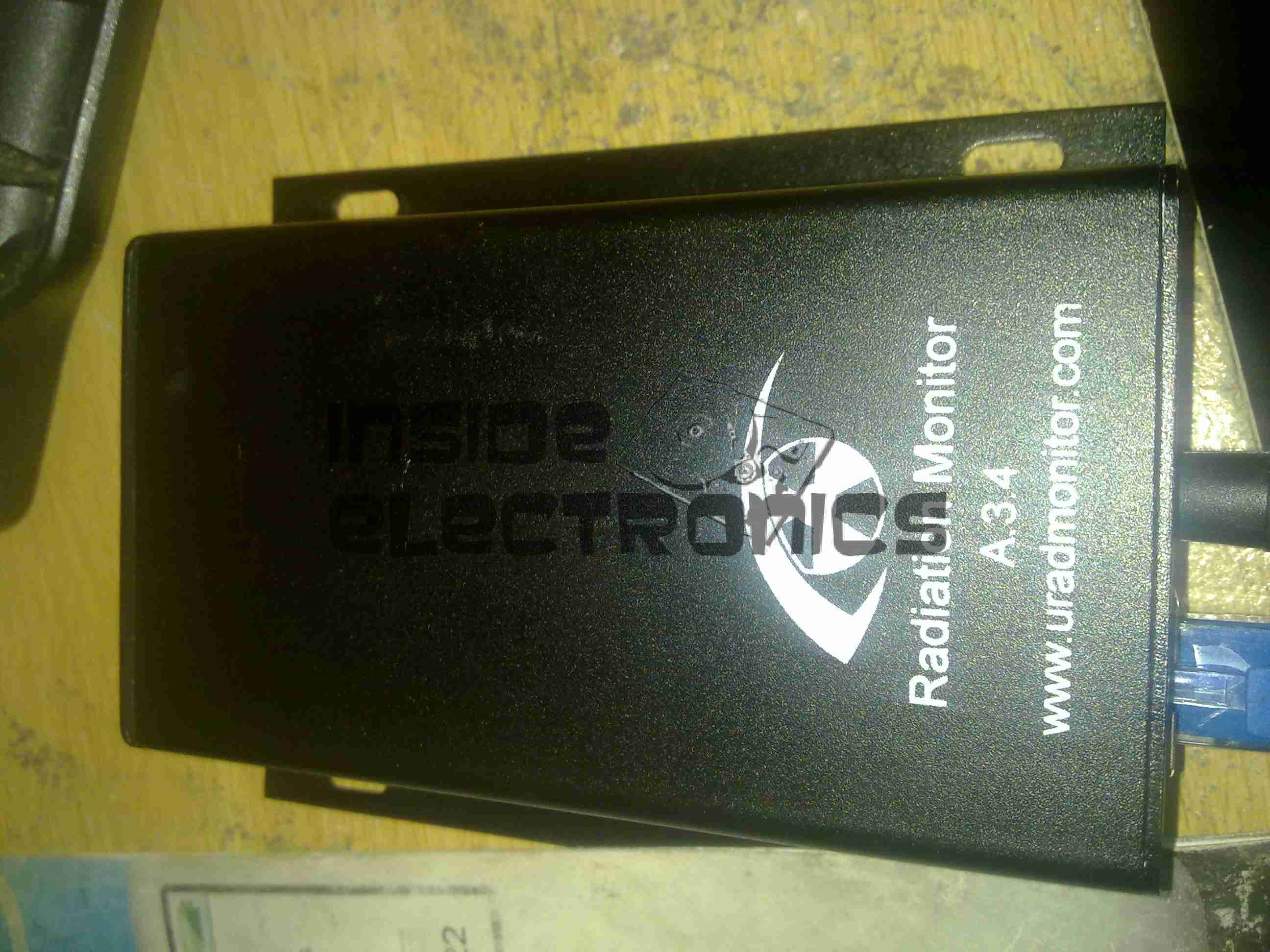
uRadMonitor
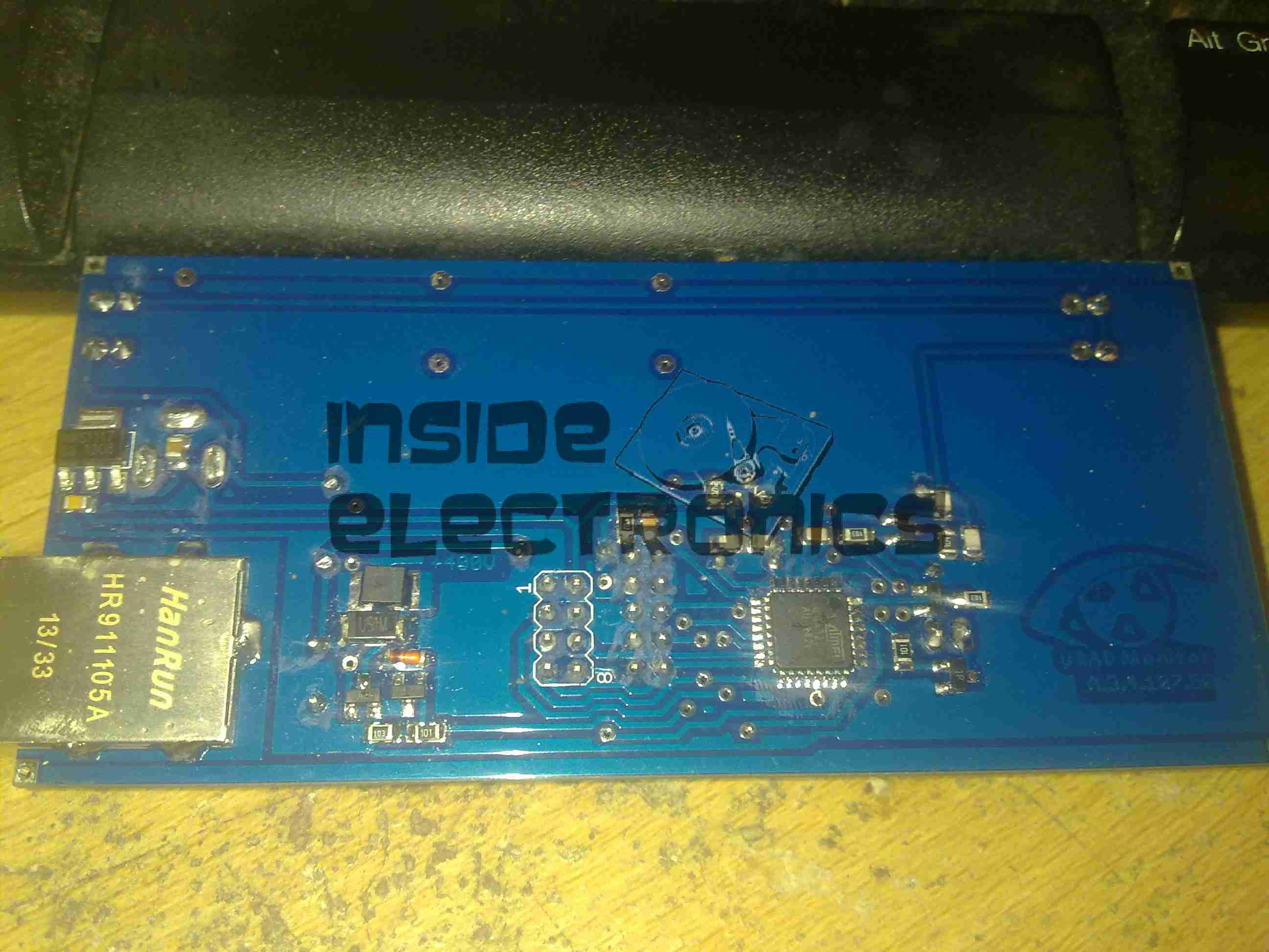
Here is the monitor, a small aluminium box, with power & network.
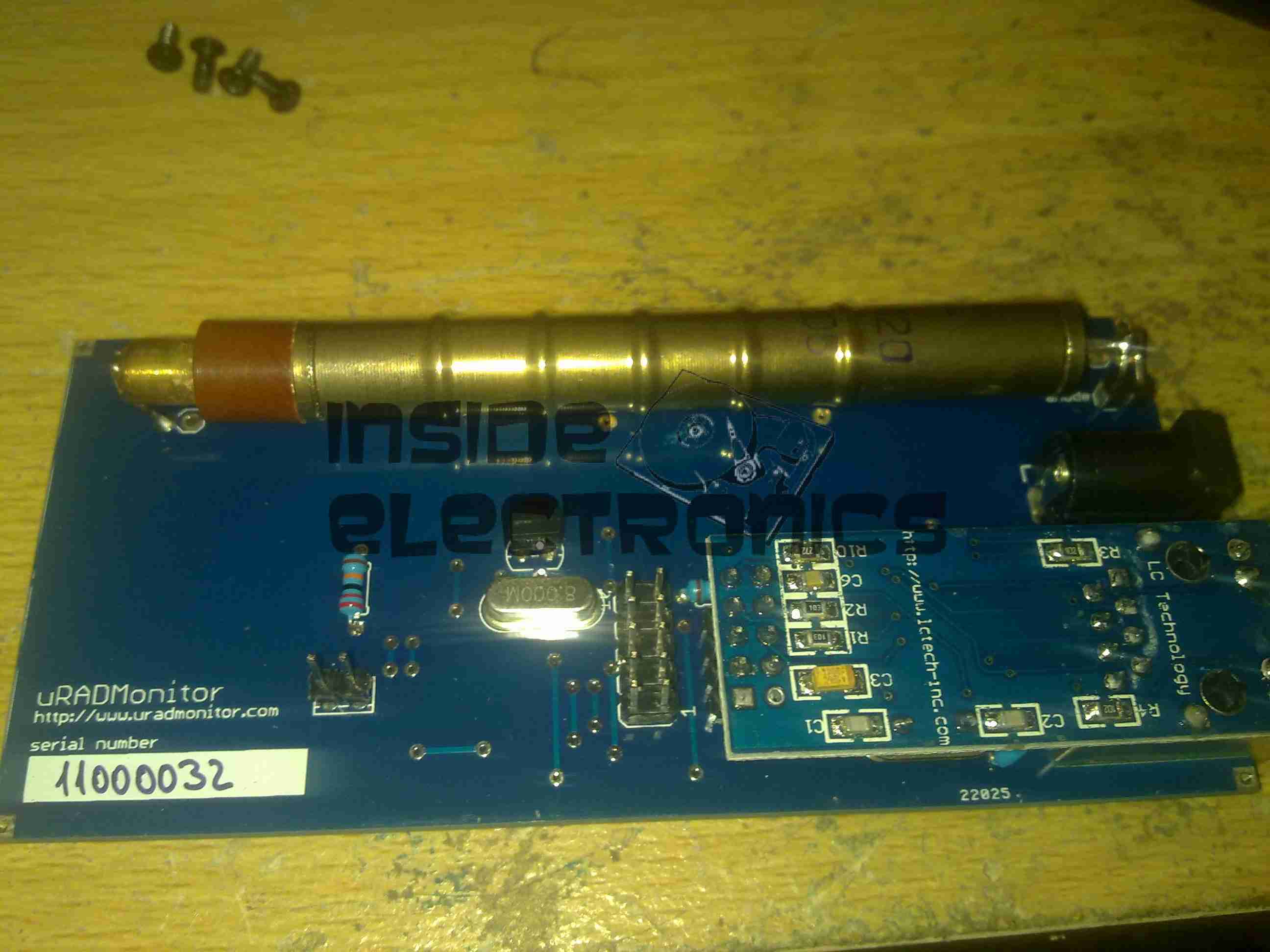
PCB
Removing 4 screws in the end plate reveals the PCB, with the Geiger-Mueller tube along the top edge. My personal serial number is also on the PCB.
The ethernet module is on the right, with the DC barrel jack.
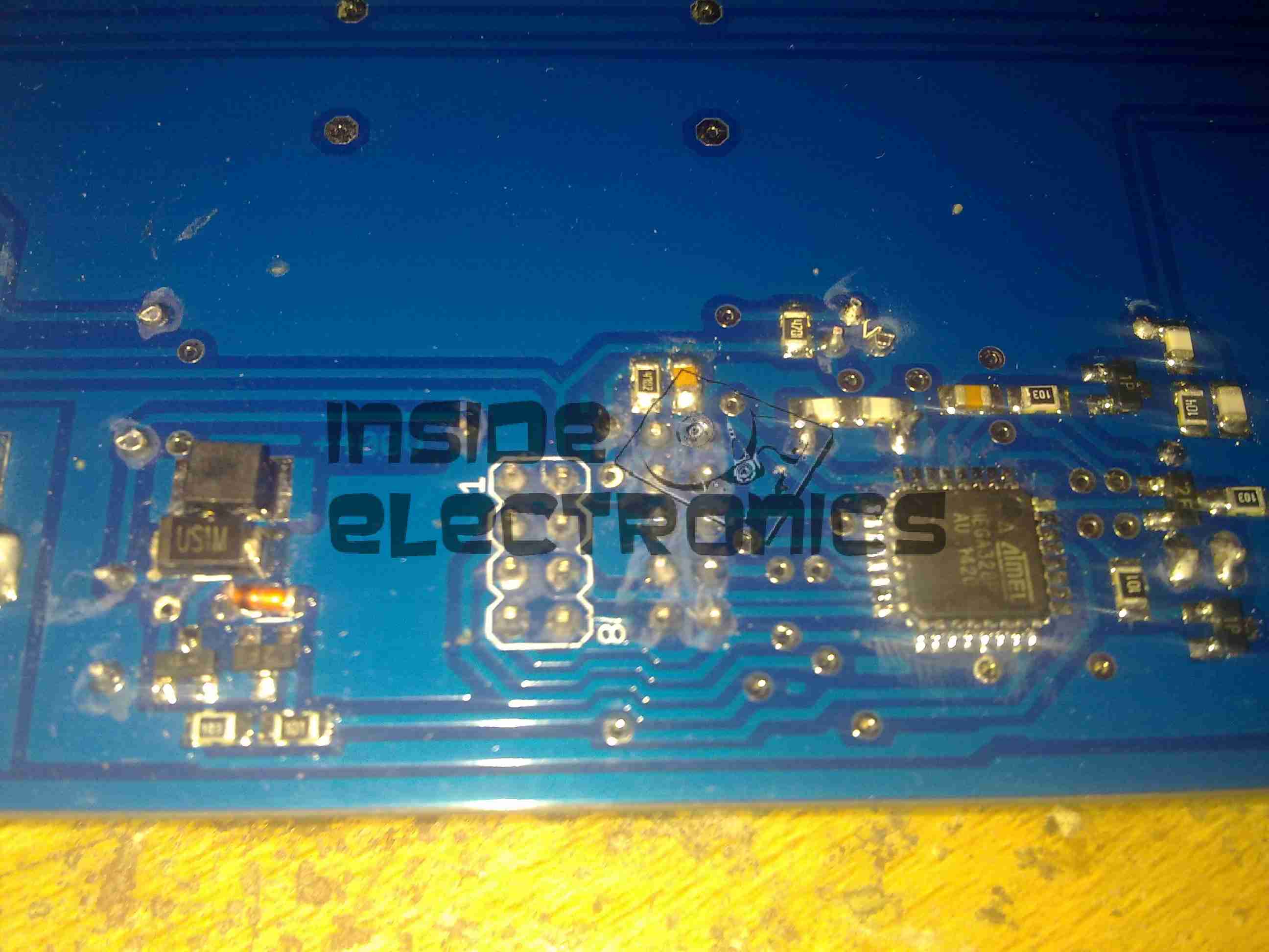
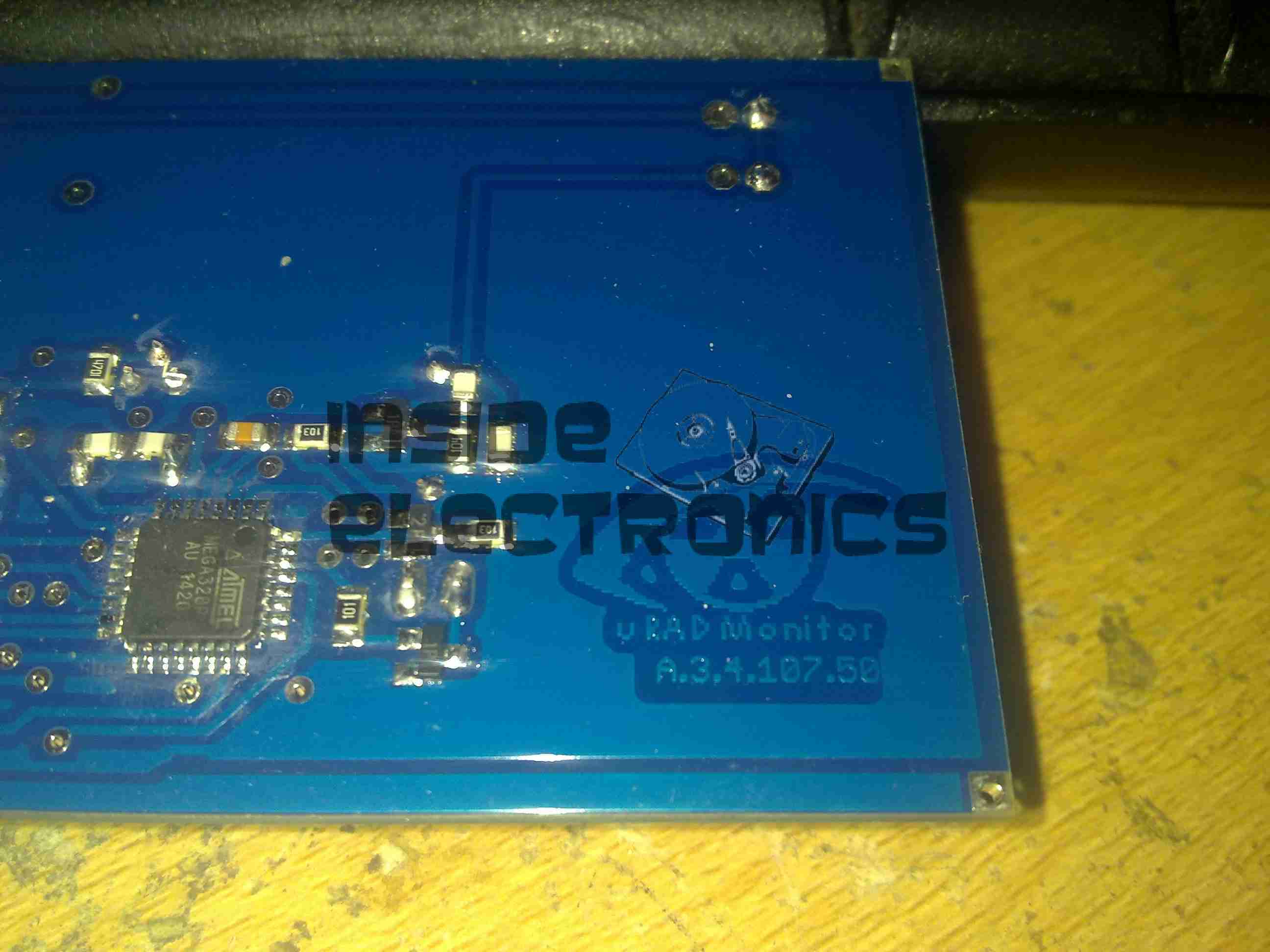
PCB Bottom
Here is the bottom of the PCB, with the control MCU & the tiny high voltage inverter for the Geiger tube.
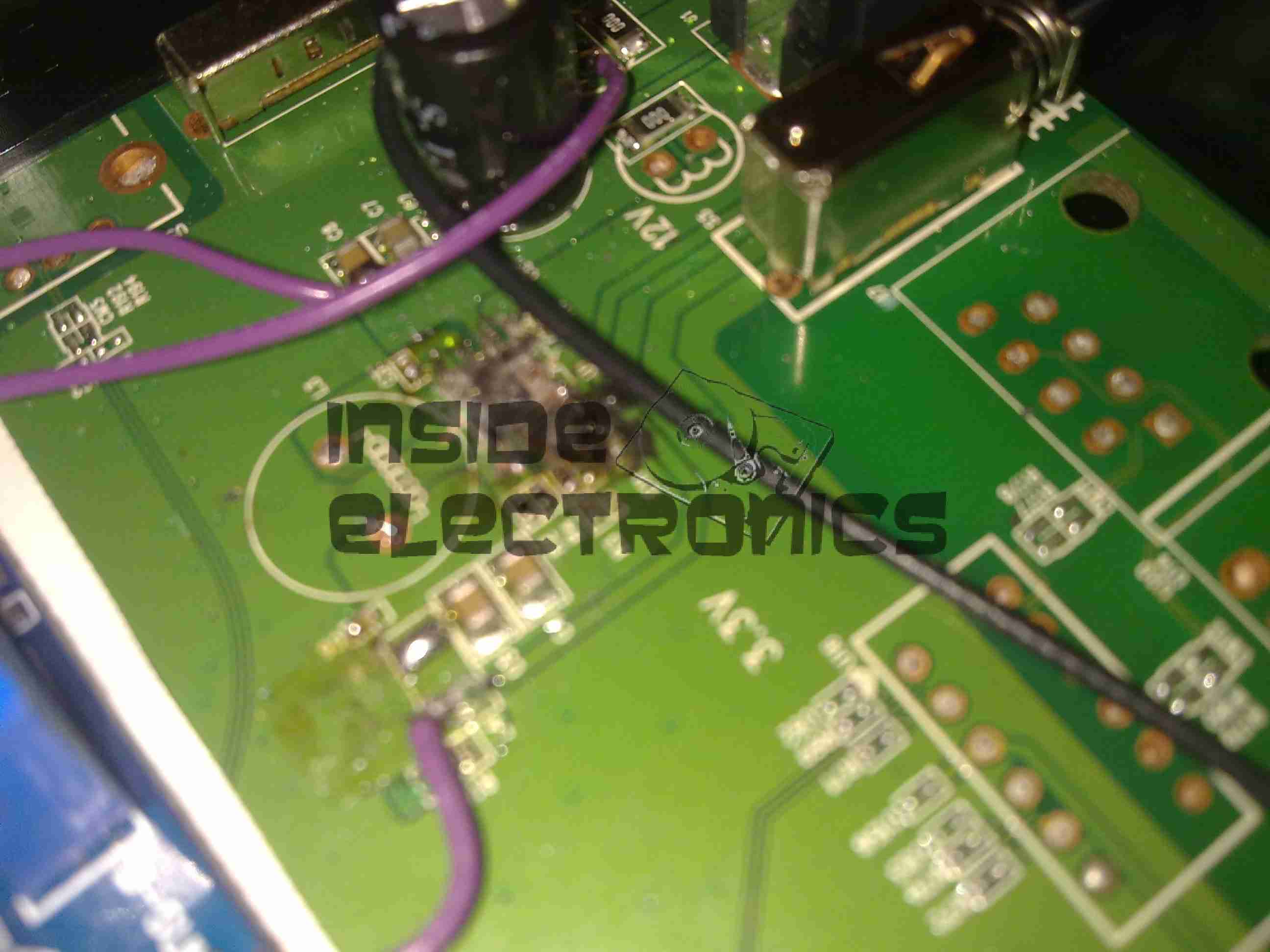
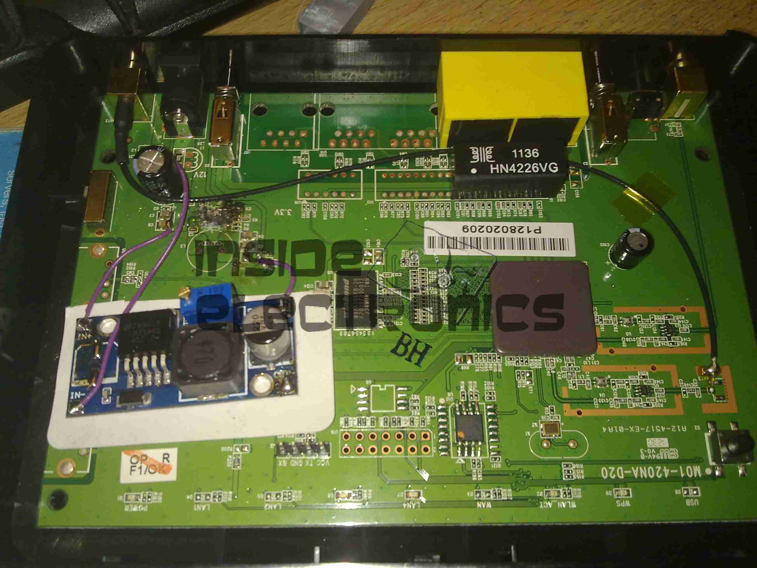
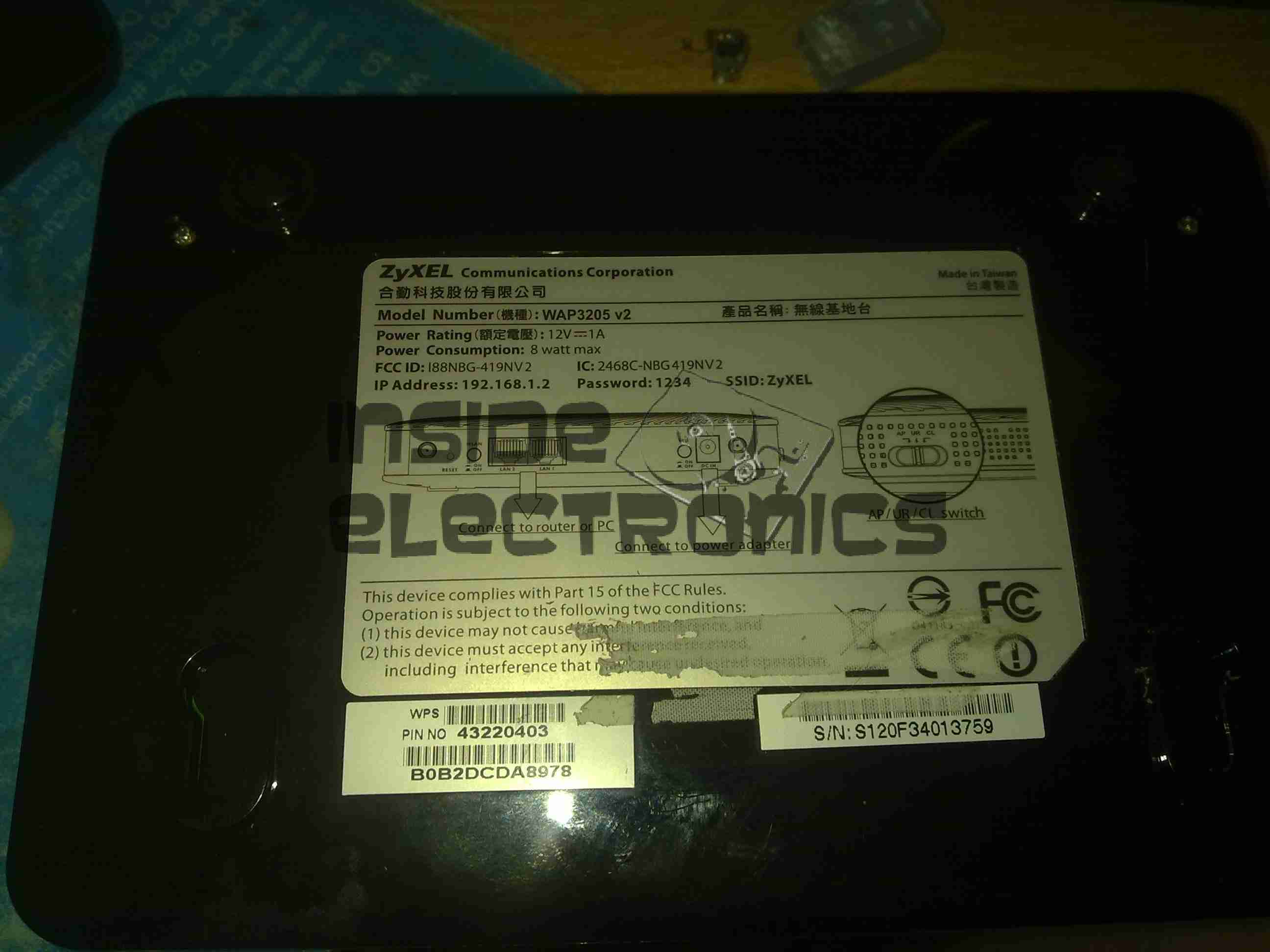
Here is a ZyXel WAP3205 WiFi Access Point that has suffered a reverse polarity event, due to an incorrect power supply being used with the unit.
ZyXEL WAP3205
While most electronic gadgets are protected against reverse polarity with a blocking diode, this unit certainly wasn’t. Applying +12v DC the wrong way round resulted in this:
Blown Switchmode IC (Fuzzy Focus)
That is the remains of the 3.3v regulator IC, blown to smithereens & it even attempted an arson attack. Luckily this was the only damaged component, & I was able to repair the unit by replacing the switching IC with a standalone regulator. (Replacing the IC would have been preferable, if there was anything left of it to obtain a part number from).
I scraped away the pins of the IC to clear the short on the input supply, removed the switching inductor, & tacked on an adjustable regulator module set to 3.3v. Luckily the voltage of the supply is handily marked on the PCB next to the circuit.
Replacement PSU
Replacement SMPS in place on top of the PCB. The output of the supply is connected to one of the pads of L4 (on my unit just an 0 ohm link), the +12v input is connected to the + rail side of C8 & C7 & the final ground connection is hooked in to the back of the barrel jack.
After this replacement, the unit booted straight up as if nothing had happened. All the logic is undamaged!
OK, a few revisions have been made to the water management PCB, mainly to reduce the possibility of the brushed DC motors in the water pumps from causing the MCU to crash, with the other changes to the I/O connector positioning & finally upgrading the reverse blocking diode to a 10A capable version rather than 5A.
I received this USB supply with a laser module from China that I purchased on eBay. I have heard of these nasty copies of Apple chargers going around, but I’d never received one this bad with a piece of Chinese electronics.
Label
Model No. A1265, so definitely an Apple clone. Apparently capable of +5v DC 1A output. Notice the American NEMA pins. This wouldn’t have been any use to me in the first instance since I am resident in the UK & our mains plugs are significantly different, not to mention significantly safer.
Manufacturer is marked as Flextronics.
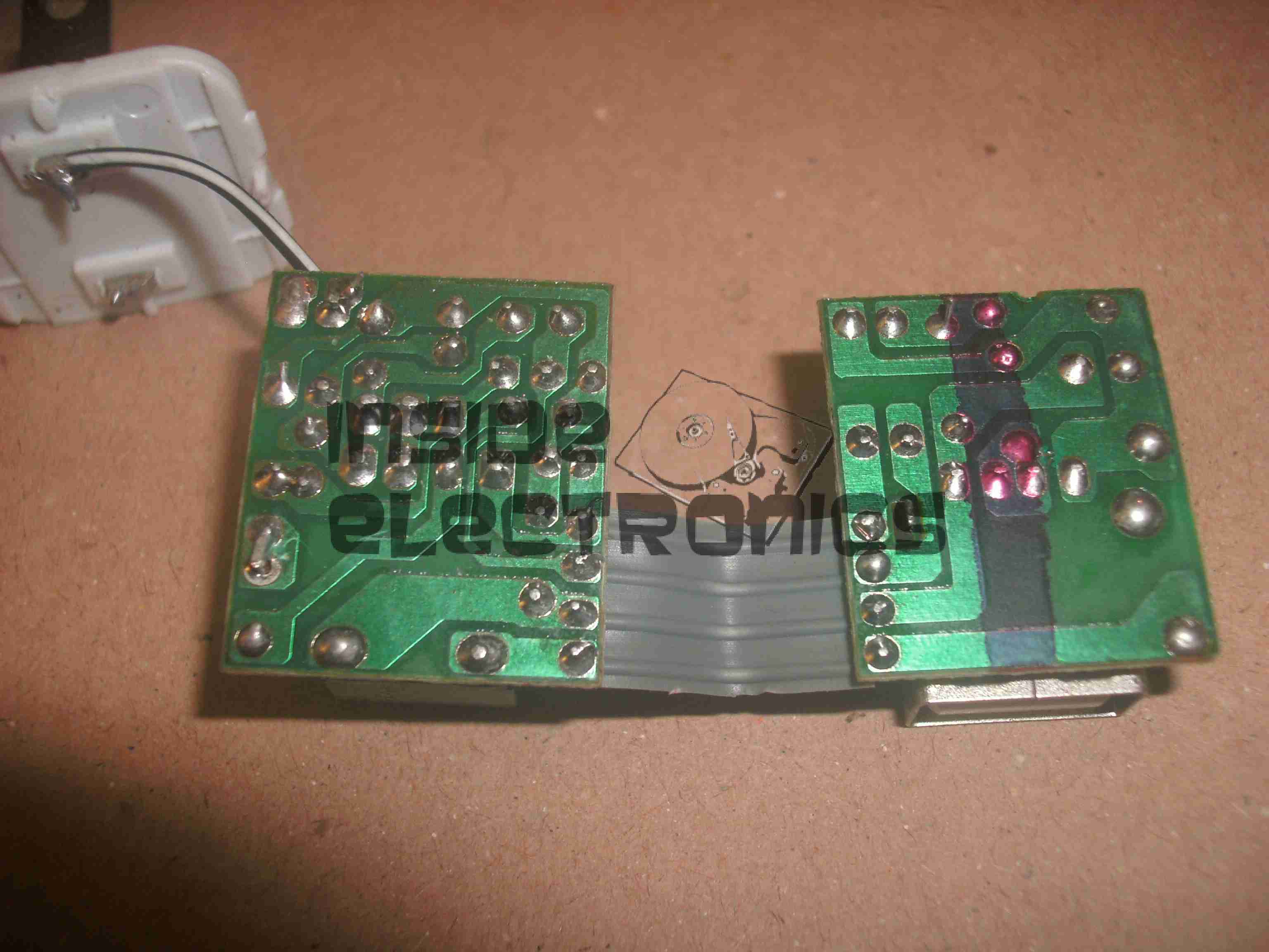
Top Of Boards
Here is the charger disassembled. Inside the case these two boards are folded together, creating an alarmingly small isolation gap between the mains side of the supply & the 5v output. Both the low voltage output & the feedback loop for the supply runs over the 4-core ribbon cable.
The mains wiring from the board is as thin as hair, insulation included, so there is a big possibility of shorts all over the place from this part of the circuit alone.
Bottom Of Boards
Bottom of the PCB assemblies. Good luck finding any creepage distance here. There simply isn’t any at all. traces on the +350v DC rail on the mains side of the transformer are no more than 1mm away from the supposedly isolated low voltage side.
Plugging one of these devices into anything is just asking for electrocution.
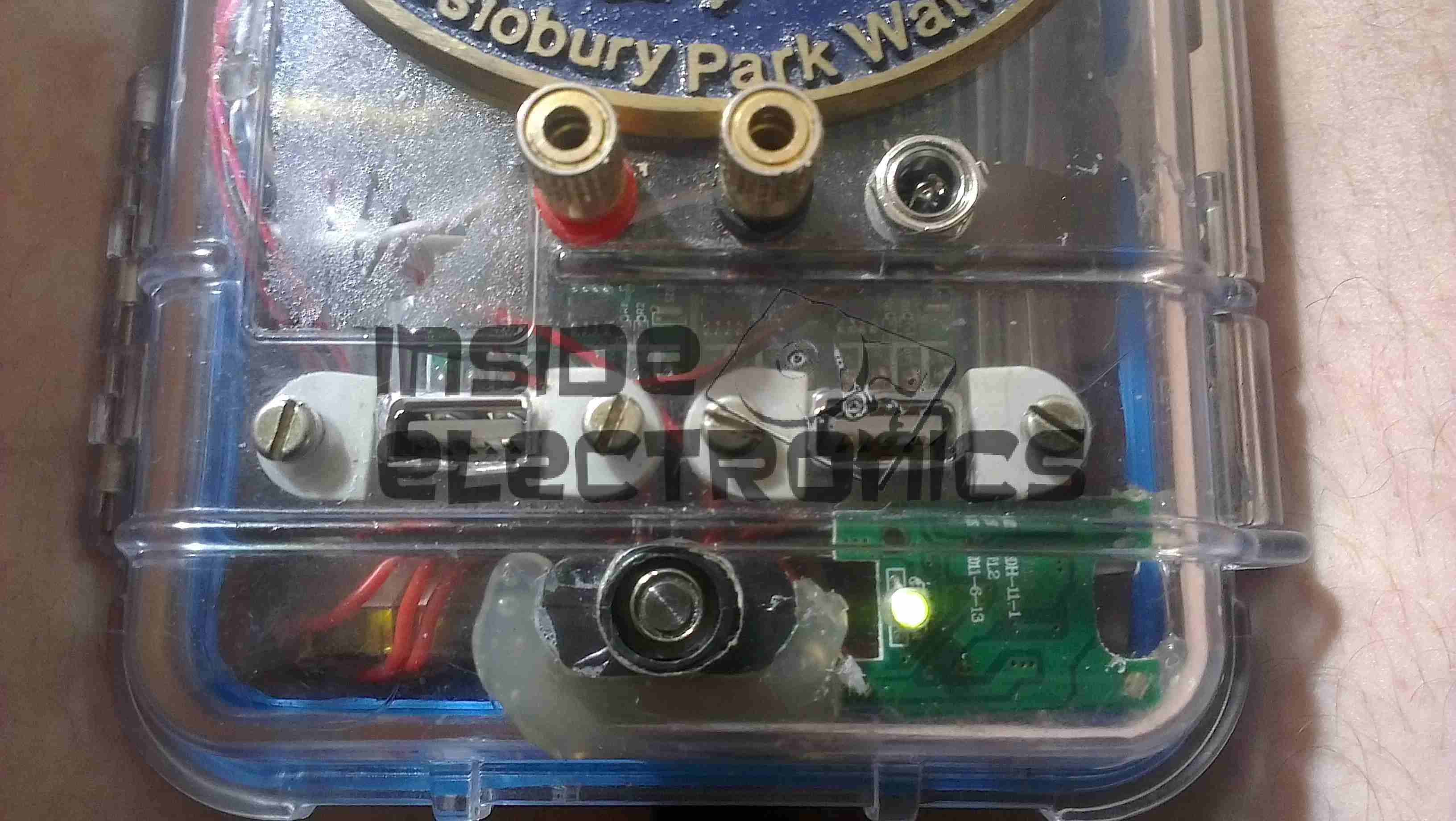
The original LM2577 based regulators I designed into my mobile battery pack turned out to be insufficient for requirements, therefore they have been replaced with higher capacity regulators.
The 12v regulator (left) is a muRata UQQ-12/8-Q12P-C SEPIC converter, providing a max of 8A at 12.1v DC. The 12v rail is also now independently switchable to save power when not in use.
The 5v regulator (right) is a Texas Instruments PTN78020WAZ switching regulator, rated at 6A. The pair of resistors on the back of the regulator set the output voltage to 5.1v.
Also a new addition is a pair of banana sockets & a 2.1mm DC jack, wired into the 12v DC bus, for powering various accessories.
New Additions
Below the USB sockets is now a built in eCig charger, to save on USB ports while charging these devices.
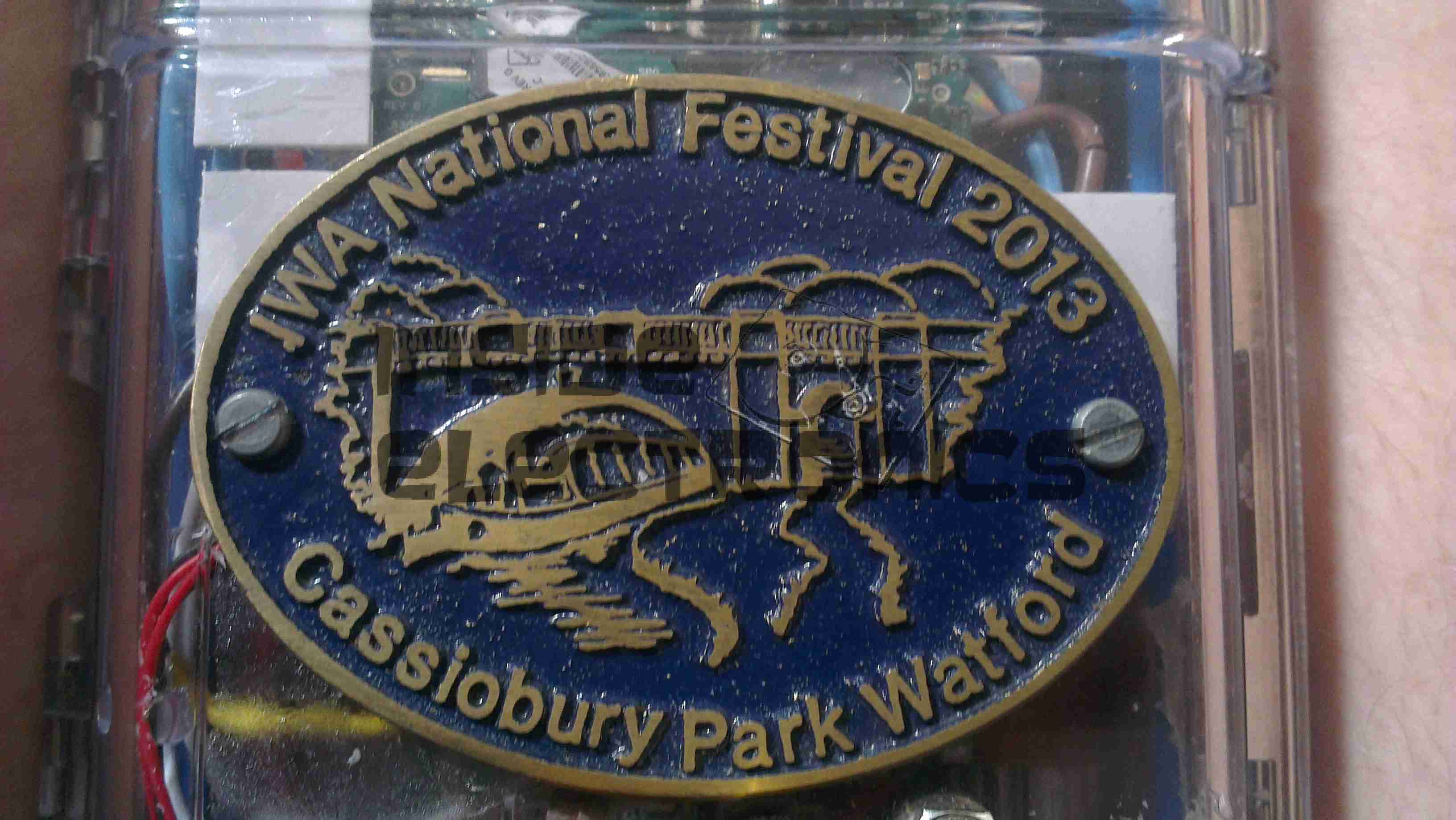
IWA National Festival 2013
These changes were made after much field testing of the unit at Cassiobury Park, Watford, for the IWA National Waterways Festival.
Progress is finally starting on the power supply unit for the Pi, fitted into the same case style as the Pi itself, this is an 8Ah Li-Poly battery pack with built in voltage regulation.
Regulator Boards
Here are the regulators, fixed to the top of the enclosure. These provide the 12v & 5v power rails for the Pi unit, at a max 3A per rail.
Battery Pack
In the main body of the case the battery pack is fitted. This is made up of 4 3-cell Li-Poly RC battery packs, rated at 2Ah each. All wired in parallel this will provide a total of 8Ah at 12.6v when fully charged.
Powered Up
Here the regulators are powered up from a 13v supply for testing. I have discovered at full load these modules have very bad ripple, so I will be adding extra smoothing capacitors to the power rails to compensate for this.
I/O
Here are the connectors on the top of the unit, outputting the two power rails to the Pi & the DC barrel jack that will be used to charge the pack.
Here is the project I’m currently working on. A completely wearable computing platform based on the Raspberry Pi & the WiFi Pineapple.
Above can be seen the general overview of the current unit.
On the left:
Alfa AWUS036NHA USB High Power WiFi Network Interface
512MB Model B Raspberry Pi, 16GB SD card, running Raspbian & LXDE Desktop. Overclocked to 1GHz.
On the right:
WiFi Pineapple router board
USB 3G card.
The WiFi, Pineapple & 3G all have external antenna connections for a better signal & the whole unit locks onto the belt with a pair of clips.
The Raspberry Pi is using the composite video output to the 7″ LCD I am using, running at a resolution of 640×480. This gives a decent amount of desktop space while retaining readability of the display.
The case itself is a Pelican 1050 hard case, with it’s rubber lining removed. The belt clips are also a custom addition.
Connections
Here are the connections to the main unit, on the left is the main power connector, supplying +5v & +12v DC. The plug on the right is an 8-pin connection that carries two channels of video, mono audio & +12v power to the display.
Currently the only antenna fitted is the 3G.
Connectors
Closeup of the connections for power, audio & video. The toggle switch is redundant & will soon be replaced with a 3.5mm stereo jack for headphones, as an alternative to the mono audio built into the display.
Test Run
Current state of test. Here the unit is running, provided with an internet connection through the Pineapple’s 3G radio, funneled into the Pi via it’s ethernet connection.
Pi Goodness!
Running on a car reversing camera monitor at 640×480 resolution. This works fairly well for the size of the monitor & the text is still large enough to be readable.
Stay tuned for Part 2 where I will build the power supply unit.
In preparation for my laser scanner project, I have modified my existing 445nm laser to accept a TTL blanking input. The laser driver is already enabled for this & just required an extra connection to interface with my laser scanner showboard. I have used an 8-pin connection to allow the same cable & interface to be used with an RGB laser system, when it arrives. The signals are as follows, from top centre, anti-clockwise:
Pin 1: +12v Power
Pin 2: Blue TTL
Pin3: GND
Pin 4: Green TTL
Pin 5: GND
Pin 6: Red TTL
Pin 7: GND
Centre: Power GND
Custom TTL Cable
Here is the custom 8 core cable, which connects to the laser scanner show board. This cable allows the laser to be used for projection while still retaining the portable function & the keylock arming switch. When plugged in the cable bypasses the keyswitch & provides 12v DC direct to the laser driver.
Here are a few details of a valve amplifier I am building, using the valve related parts from a 1960’s reel to reel tape recorder.
This amplifier is based on an a Mullard ECL82 triode/pentode valve, with an EM84 magic eye tube for level indication.
Beginnings Of The Amplifier
Here the first components are being soldered to the tags on the valve holder, there are so few components that a PCB is not required, everything can be rats-nested onto the valve holders.
Progress
Progressing with the amplifier section componentry, all resistors are either 1/2W or 2W.
Valve Sockets Fitted
Here the valve holders have been fitted, along with the output transformer, DC smoothing capacitor & the filament wiring, into the top of the plastic housing. At this point all the components that complete the amplifier section are soldered to the bottom of the right hand valve holder.
Wiring
Starting the wiring between the valves & the power supply components. The volume control pot is fitted between the valve holders.
Valves Test Fit
The valves here are test fitted into their sockets, the aluminium can at the back is a triple 32uF 250v electrolytic capacitor for smoothing the B+ rail.
Amplifier Section First Test
First test of the amplifier, with the speaker from the 1960’s tape recorder from which the valves came from. the 200v DC B+ supply & the 6.3v AC filament supply is derived from the mains transformer in the background.
Magic Eye Tube Added
Here the magic eye tube has been fitted & is getting it’s initial tuning to the amplifier section. This requires selecting combinations of anode & grid resistors to set the gap between the bars while at no signal & picking a coupling RC network to give the desired response curve.
Final Test
Here both valves are fitted & the unit is sitting on it’s case for final audio testing. the cathodes of the ECL82 can be clearly seen glowing dull red here.
In the final section, I will build a SMPS power supply into the unit to allow it to be powered from a single 12v DC power supply.
Here is an old chemical dosing system for industrial washing machines. These units are 4-pump models, with dual pumpheads. The motors are reversed to operate alternate pumps in the same head.
Label
From 2006, this is a fairly old unit, and made in the UK.
CPU Board
Main controller PCB, with interface to the power electronics via the ribbon cable, an external serial port for programming to it’s left. Powered by an ST microcontroller. The LCD is below this board.
PCU & Driver PCBs
Main power supply, sense input & motor driver boards. The PSU outputs +5v, +12v & +24v. The inputs on the lower left connect to the washing machine & trigger the pumps via the programming on the CPU. The motors are driven by L6202 H-Bridge drivers from ST.
Motor Assembly
Motor & gearbox assembly on the back of the pumphead. These are 24v DC units with 80RPM gearboxes.
UPDATE:
As it seems to be difficult to find, here is the user manual for this unit:
[download id=”5557″]
This is the teardown of a Zebra P330i plastic card printer, used for creating ID cards, membership cards, employee cards, etc. I got this as a faulty unit, which I will detail later on.
This printer supports printing on plastic cards from 1-30mils thick, using dye sublimation & thermal transfer type printing methods. Interfaces supplied are USB & Ethernet. The unit also has the capability to be fitted with a mag stripe encoder & a smart card encoder, for extra cost.
Print Engine
On the left here is the print engine open, the blue cartridge on the right is a cleaning unit, using an adhesive roller to remove any dirt from the incoming card stock.
This is extremely important on a dye sublimation based printing engine as any dirt on the cards will cause printing problems.
Cards In Feeder
Here on the right is the card feeder unit, stocked with cards. This can take up to 100 cards from the factory.
The blue lever on the left is used to set the card thickness being used, to prevent misfeeds. There is a rubber gate in the intake port of the printer which is moved by this lever to stop any more than a single card from being fed into the print engine at any one time.
Card Feeder Belt
Here is the empty card feeder, showing the rubber conveyor belt. This unit was in fact the problem with the printer, the drive belt from the DC motor under this unit was stripped, preventing the cards from feeding into the printer.
Print Head
Here is a closeup of the print head assembly. The brown/black stripe along the edge is the row of thin-film heating elements. This is a 300DPI head.
Print Station
This is under the print head, the black roller on the left is the platen roller, which supports the card during printing. The spool in the center of the picture is the supply spool for the dye ribbon.
In the front of the black bar in the bottom center, is a two-colour sensor, used to locate the ribbon at the start of the Yellow panel to begin printing.
LCD PCB
Inside the top cover is the indicator LCD, the back of which is pictured right.
This is a 16×1 character LCD from Hantronix. This unit has a parallel interface.
LCD
Front of the LCD, this is white characters on a blue background.
Roller Drive Belts
Here is the cover removed from the printer, showing the drive belts powering the drive rollers. There is an identical arrangement on the other side of the print engine running the other rollers at the input side of the engine.
Mains Filter
Here the back panel has been removed from the entire print engine, complete with the mains input wiring & RFI filtering.
This unit has excellent build quality, just what is to be expected from a £1,200+ piece of industrial equipment.
Main Frame With Motors
The bottom of the print engine, with all the main wiring & PCB removed, showing the main drive motors. The left hand geared motor operates the head lift, the centre motor is a stepper, which operates the main transmission for the cards. The right motor drives the ribbon take up spindle through an O-Ring belt.
Feeder Drive Motor
Card feeder drive motor, this connects to the belt assembly through a timing belt identical to the roller drive system.
All these DC geared motors are 18v DC, of varying torque ratings.
Power Supply
Here is the main power supply, a universal input switch-mode unit, outputting 24v DC at 3.3A.
PSU Label
PSU info. This is obviously an off the shelf unit, manufactured by Hitek. Model number FUEA240.
Print Engine Rear
The PSU has been removed from the back of the print engine, here is shown the remaining mechanical systems of the printer.
Print Engine Components
A further closeup of the print engine mechanical bay, the main stepper motor is bottom centre, driving the brass flywheel through another timing belt drive. The O-Ring drive on the right is for the ribbon take up reel, with the final motor driving the plastic cam on the left to raise/lower the print head assembly.
The brass disc at the top is connected through a friction clutch to the ribbon supply reel, which provides tension to keep it taut. The slots in the disc are to sense the speed of the ribbon during printing, which allows the printer to tell if there is no ribbon present or if it has broken.
RFID PCB
Here is a further closeup, showing the RFID PCB behind the main transmission. This allows the printer to identify the ribbon fitted as a colour or monochrome.
The antenna is under the brass interrupter disc on the left.
I/O Daughterboard
The I/O daughterboard connects to the main CPU board & interfaces all the motors & sensors in the printer.
Main PCB
Here is the main CPU board, which contains all the logic & processing power in the printer.
CPU
Main CPU. This is a Freescale Semiconductor part, model number MCF5206FT33A, a ColdFire based 32-bit CPU. Also the system ROM & RAM can be seen on the right hand side of this picture.
Ethernet Interface
Bottom of the Ethernet interface card, this clearly has it’s own RAM, ROM & FPGA. This is due to this component being a full Parallel interface print server.
Ethernet Interface Top
Top of the PCB, showing the main processor of the print server. This has a ferrite sheet glued to the top, for interference protection.
This is the Velleman MK179 Proximity Card Reader, which is supplied in kit form. In the image above you can see the completed kit, the read coil is etched onto the black PCB on the left. Bringing a recognised card close to the coil operates the relay on the main PCB for a programmable amount of time.
Main PCB
Closeup of the main PCB, 12v DC input at top right. Left IC is an LM358 dual Op-Amp, the IC on the right is a PIC12F629 with Velleman’s custom firmware.
Logic power is supplied to the ICs & the oscillator from the LM7805 regulator at the top of the PCB. The relay is a standard 15A SPDT 12v coil relay, with the switch contacts broken out onto the screw terminals on the left.
Schematic Diagram
As it is not provided with the kit, unlike other Velleman kits, here is the schematic for this.
This unit was bought from eBay to experiment with Magnetic Stripe cards, for little money. This unit is capable of reading & writing all 3 tracks, & both Hi-Co & Lo-Co card types.
Interfaced to a PC through USB, this has a built in PL2303 USB-Serial IC & requires 3A at 9v DC to operate.
The 3 Indicator LEDs on the top of the unit can be toggled by the included software for Power/OK/Fault condition signalling.
Unit Bottom
Bottom of the unit with the model labels.
Model Label
Closeup of the model label & serial number.
PCB Bottom
Here the bottom cover has been removed, showing the main PCB. The pair of large ICs bottom center interface with the magnetic heads. The IC above them has had the markings sanded off.
USB-Serial Interface
Closeup of the Prolific PL-2303 USB-Serial converter IC.
PCB Top
Here the connections to the R/W heads are visible, current limiting resistors at the left for the write head, a pair of signal relays, a pair of optoisolators & a LM7805 linear voltage regulator.
LEDs
Here is the trio of indicator LEDs on a small sub-board.
Frame Bottom
The PCB has been removed from the main frame here, the only component visible is the rotary encoder.
Rotary Encoder
The rotary encoder has a rubber wheel fitted, which reads the speed of the card as it is being swiped for writing. This allows the control logic to write the data to the stripe at the correct rate for the speed of the card. This allows the unit to write cards from 5-50 inches per second speed.
The Write head is directly behind the rubber pressure roller.
Read/Write Heads
Here you can see the R/W head assembly. The write head is on the right, read on the left. When a card is written to, it immediately gets read by the second head for verification.
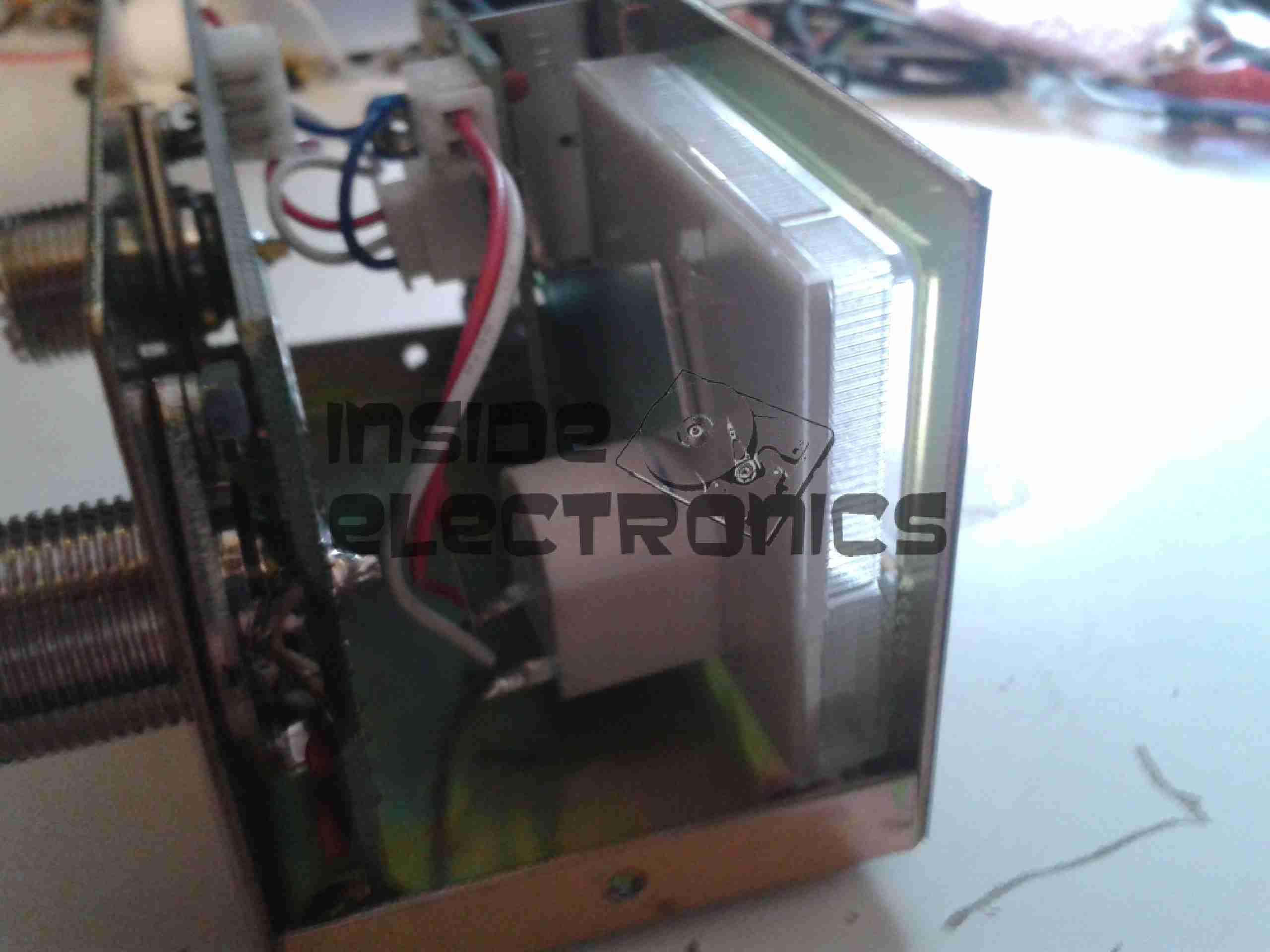
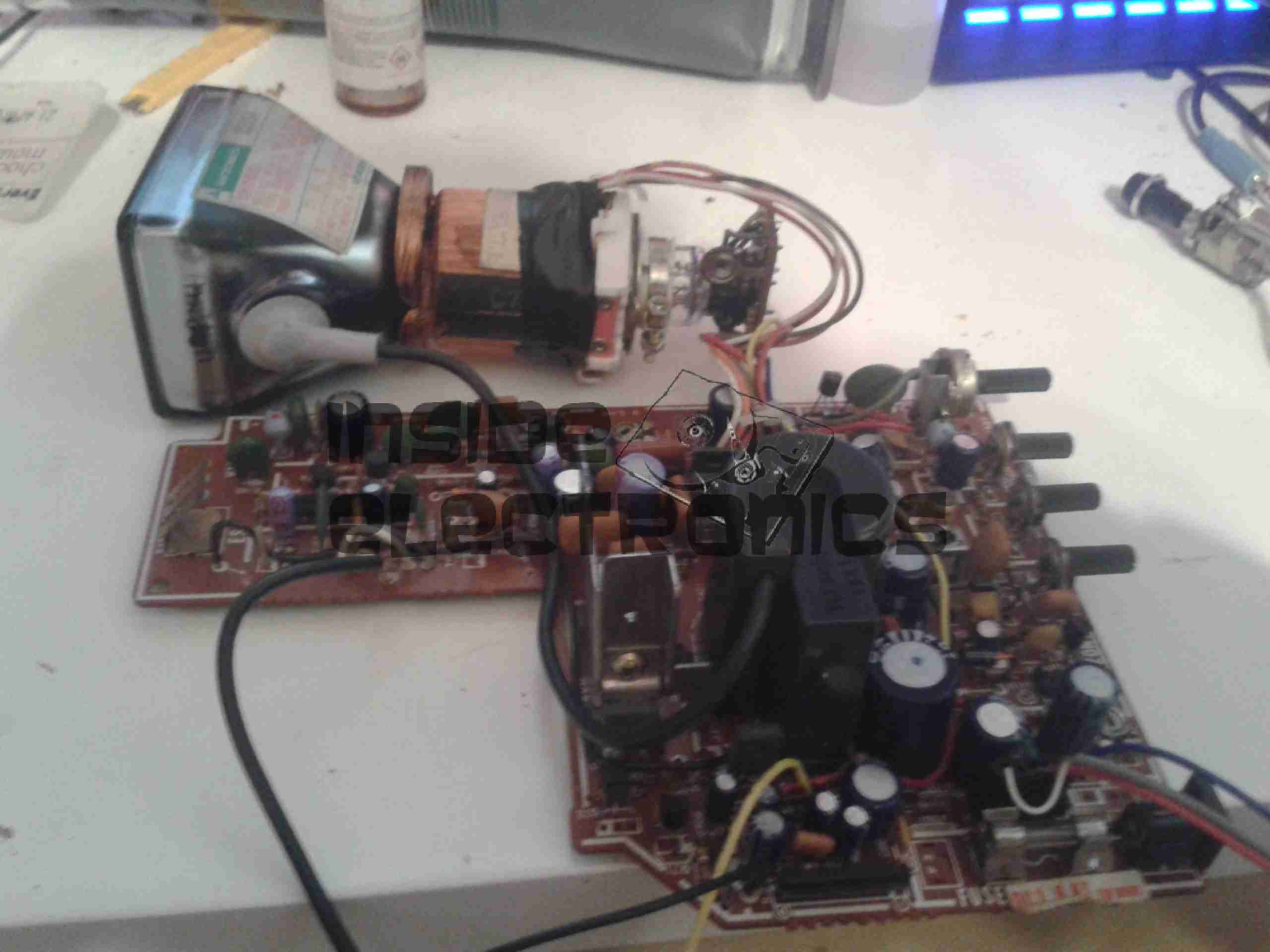
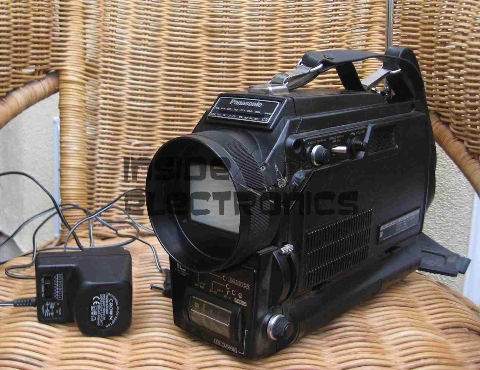
Here are the viewfinder electronics from a 1984 Hitachi VHS Movie VM-1200E Camcorder. These small CRT based displays accept composite video as input, plus 5-12v DC for power.
Screen
Here is the front face of the CRT, diameter is 0.5″.
Power Board
Closeup view of the PCB, there are several adjustments & a pair of connectors. Socket in the upper left corner is the power/video input. Pinout is as follows:
Brown – GND
Red – Video Input
Orange – +12v DC
Yellow – Record LED
The potentiometers on the PCB from left:
H. ADJ
V. ADJ
BRIGHT
FOCUS
PCB Part Number reads: EM6-PCB
This unit utilises the BA7125L deflection IC.
Solderside
Reverse side of the PCB, very few SMT components on this board.
Tube Assembly
Here is an overall view of the CRT assembly with scan coils. Tube model is NEC C1M52P45.
Electron Gun
Closeup view of the CRT neck, showing the electron gun assembly.
CCTV Camera
The old CCTV camera used to feed a composite signal to the CRT board. Sanyo VCC-ZM300P.
CCTV Camera Connections
Connections at the back of the camera. Red & Black pair of wires lead to 12v power supply, Green & Black pair lead to the CRT board’s power pins. Seperate green wire is pushed into the BNC video connector for the video feed. video ground is provided by the PSU’s ground connection.
Connections
Finally the connections at the CRT drive board, left to right, +12v, Video, GND.
This is a small 120W power inverter, intended for small loads such as lights, fans, small TVs & laptop computers.
End Cover
End cover of the unit, 12v DC input cord at the top, power switch & indicator LEDs at the bottom.
Mains Output
Opposite end of the unit, with the standard 240v AC 50Hz Mains output socket.
Cover Removed
Cover removed from the top of the unit. Main power transformer is visible in the centre here, MOSFET bank is under the steel clamp on the left, the aluminium case forms the heatsink.
PWM Controllers
On the right is a KA3525 switchmode PWM controller & on the left is a LM324N quad Op-Amp IC. The buzzer on the far left is for the low battery warning.
PCB Removed
PCB removed from the casing, with the MOSFET bank on the right hand side. Two potentiometers in the centre of the board tweak the frequency of the switcher & the output voltage.
Tip Jar
If you’ve found my content useful, please consider leaving a donation by clicking the Tip Jar below!
All collected funds go towards new content & the costs of keeping the server online.